1998 HONDA CR-V idler pulley
[x] Cancel search: idler pulleyPage 100 of 1395
Engine Removal/lnstallation
Removal (cont'dl
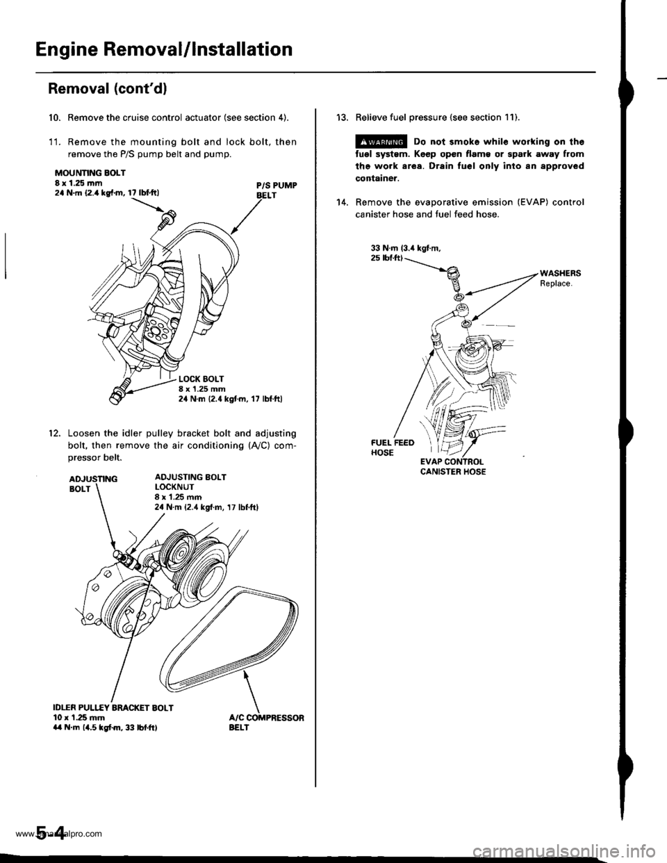
Remove the cruise control actuator (see section 4).
Remove the mounting bolt and lock bolt, then
remove the P/S pump belt and pump.
10.
1t.
MOUNNNG BOLT8 x 1.25 mm2a N.m 12.4 kg{.m, 17 lbtftlP/S PUMPBELT
LOCK BOLTI x 1.25 mm24 N.m {2.4 kgtm, '17 lbf.ftl
12.Loosen the idler pulley bracket bolt and adjusting
bolt, then remove the air conditioning (A,/C) com-
pressor belt.
ID1TR PULI.f,Y ARACKET BOLT10 r 1.25 mma{ N.m 14.5lgtm,33 lbf.ft)
ADJUSTING BOLTLOCKNUT8 x 1.25 mm24 N.m {2.4 kgf.m, 17 lbf.ftl
5-4
13. Relieve fuel pressure {see section 11).
@ Do not 3mok6 whil€ working on th6
tugl systsm. Koep open flam€ or spark away from
the work area. Drain fuel only inlo an approved
container.
14. Remove the evaporative emission (EVAP) control
canister hose and tuel feed hose.
33 N.m (3.4 kgt.m,2s tbf.ft)
,%l
*ryft'fltr
\'t,f
EVAP CCCANISTER HOSE
www.emanualpro.com
Page 123 of 1395
Timing Belt
Removal
Replace the timing belt at 105,000 miles (168,000 km)
according to the maintenance schedule {normal condi-
tions/severe conditions). lf the vehicle is regularly driven
in either of the following conditions, replace the timing
belt at 60,000 miles (U.S.A.l 100.000 km (Canada).
- ln very high temperatures (over 110'F, 43"C).- In very low temperatures (under -20"F. -29"C).
Turn the crankshaft pu\ley so the No. 1 piston is at
top dead center (TDC).
Remove the guard bar and splash shield (see page
5-7 ).
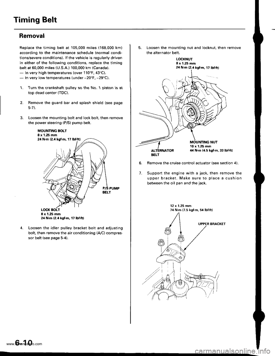
Loosen the mounting bolt and lock bolt. then remove
the power steering (P/S) pump belt.
MOUNNNG BOLT8 x 1.25 rnm
1.
2.
,l
4. Loosen the idler pulley bracket bolt and adjusting
bolt, then remove the air conditioning (lVC) compres
sor belt (see page 5-4).
6-10
24 N.m {2.4 kgt.m, 17 lbf.ftl
24 N.m 12.4 kgf.m, lt lbf.ftl
5. Loosen the mounting nut and locknut, then remove
the altefnator belt.
LOCKNUTI x 1.25 mm2a N.m 12.4 kgt m, 17 lblftl
6.
10 x 1,25 mm4,1 N.m (,1.5 kgt m, 33 lbtftl
Remove the cruise control actuator (see section 4).
Support the engine with a jack, then remove the
upper bracket. Make sure to place a cushion
between the oil Dan and the iack.
12 x 1.25 mm74 N.m (7.5 kgf m, 54 lbtftl
7.
BRACKET
AELT
www.emanualpro.com
Page 126 of 1395

CKF Sensor
Replacement
1.
|o|'ln PUUCY BMCKET SOLIl0 r 1.25 mm14 .m 14.5 kgl.m,3:' lbtftl
Remove the guard bar and splash shield (see page
5-7 t.
Loosen the lock bolt and mounting bolt, then
remove the P/S pump belt.
MOUNTING BOLT8 x 1.25 mm
PUMPBELT
Loosen the adjusting bolt and idler pulley bracket
bolt, then remove the Ay'C comDressor belt.
ADJUSTING BOLTLOCKNUT8 x 1.25 mm24 N.m {2.4 kgf.m, 17 lbf.ft)
24 N.m (2.{ kgf.m, 17 lbf.ttl
24 N.m 12.4 lgf.m, 17 lbl.ftl
4. Loosen the locknut and mounting nut, then remove
the alternator belt.
LOCKNUT8 x 1.25 mm24 N.m (2.4 kgl.m, 17 lbtftl
10 x 1 .25 mma4 N.m (4.5 kgt m, 33 lbtft)
E
6.
7.
aJ.
Remove the cylinder head cover.
Remove the crankshaft pulley (see page 6-7).
Remove the middle cover and the lower cover.
Disconnect the CKF sensor connector, then remove
the CKF sensor.
6x1.0mm11 N.m {1.r kgnm,8.0 lbfft)
9. Install the CKF sensor in reverse order of removal.
BELT
CKF SENSOR
6-13
www.emanualpro.com
Page 129 of 1395
Gylinder Head
Removal
Engine removal is not required for this procedure.
l!@ Make sure iacks and safety stands are
placed properly, and hoist blackels ale attachgd to the
correct position on the engine.
NOTE:
o Use fender covers to avoid damaging painted sur-
faces.
o To avoid damage, unplug the wiring connectors care-
fully while holding the connector portion.
. To avoid damaging the cylinder head, wait until the
engine coolant temperature drops below 100"F (38'C)
before loosening the retaining bolts.
. Mark all wiring and hoses to avoid misconnection.
Also, be sure that they do not contact other wiring or
hoses, or interfere with other parts.
2.
4.
5.
1.Disconnect the negative terminal from the battery.
Drain the engine coolant (see page 10-5). Remove
the radiator cap to speed draining.
Remove the intake air duct and air cleaner housing(see page 5-2).
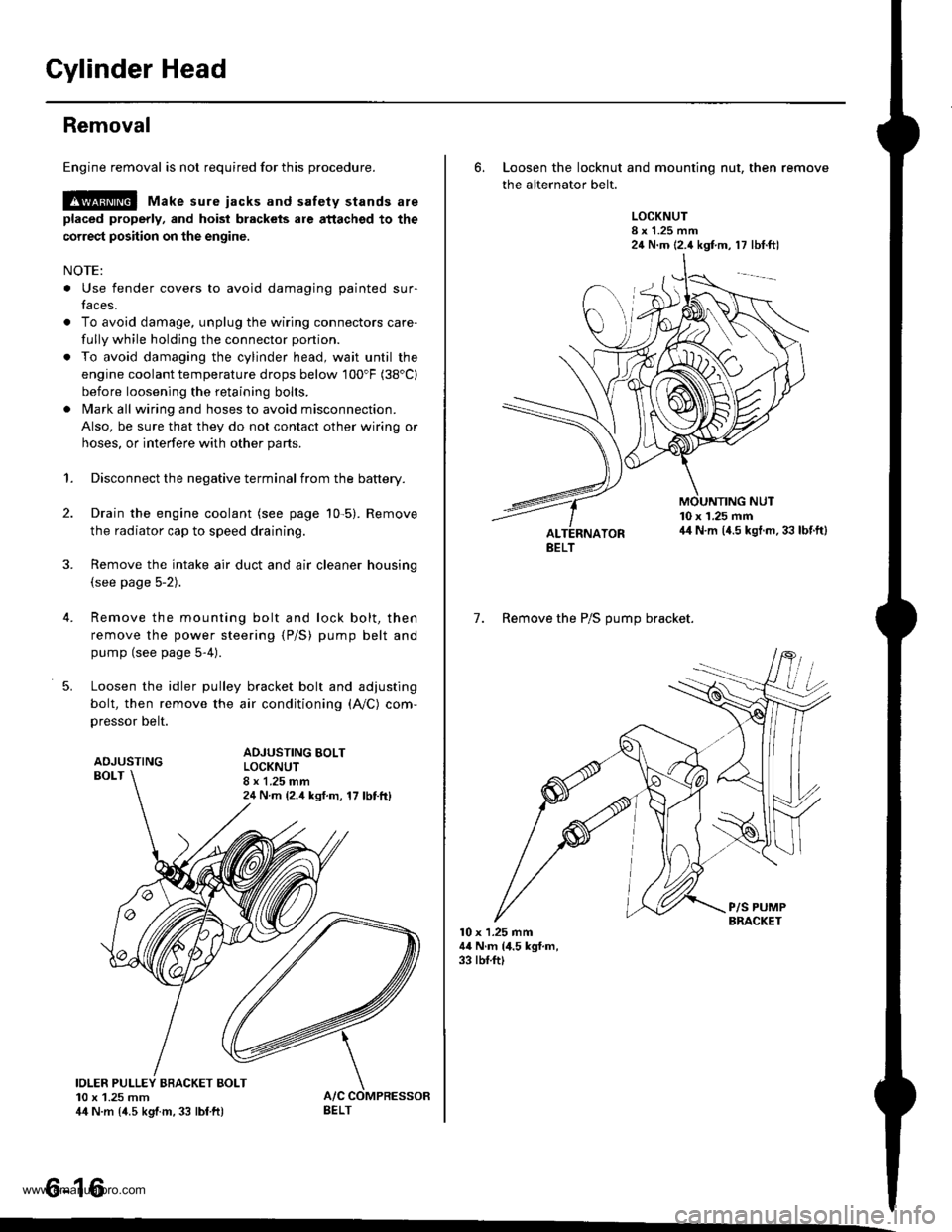
Remove the mounting bolt and lock bolt, then
remove the power steering (P/S) pump belt and
pump (see page 5-4).
Loosen the idler pulley bracket bolt and adjusting
bolt, then remove the air conditioning (A,/C) com,
pressor belt.
ADJUSTINGBOLT
ADJUSTING BOLTLOCKNUT8 x 1.25 mm24 N m {2.4 ksf.m, 17 lbttt}
IOLER PULLEY BBACKET BOLT10 x 1.25 mm44 N.m {4.5 kgtm, 33 lbf ft)
tt aAo-Io
6. Loosen the locknut and mounting nut, then remove
the alternator belt.
LOCKNUT8 x 1.25 mm24 N.m (2.4 kgf.m, 17 lbt.ftl
10 x 1.25 mm44 N.m (4.5 kgt.m. 33 lbf.ft)
7. Remove the P/S OUmo bracket.
l0 x 1.25 mm44 N.m (4.5 kgf.m,33 rbf.ft)
BELT
www.emanualpro.com
Page 1152 of 1395
Compressor
Replacement
lf the compressor is marginally operable. run the
engine at idie speed, and let the air conditioner
work for a few minutes. then shut the engine off.
Disconnect the negative cable from the battery.
Recover the refrigerant with a recovery/recycling/
charging station (see page 22-59).
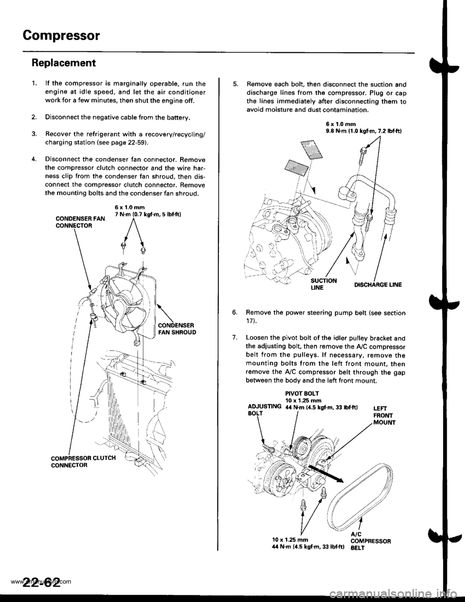
Disconnect the condenser fan connector. Remove
the compressor clutch connector and the wire har-
ness clip from the condenser fan shroud, then dis-
connect the compressor clutch connector. Remove
the mounting bolts and the condenser fan shroud,
CONDENSER FANCONNECTOR
6x1.0mm7 N.m 10.7 kg{.m, 5 lbl.ftl
'L
2.
5. Remove each bolt, then disconnect the suction and
discharge lines from the compressor. Plug or cap
the lines immediately after disconnecting them to
avoid moisture and dust contamination,
6x1.0mm9.8 N.m 11.0 kgf.m,7.2 lbf.ft)
DISCHARGE LINE
Remove the power steering pump belt (see section
17t.
Loosen the pivot bolt of the idler pulley bracket and
the adiusting bolt, then remove the Ay'C compressor
belt from the pulleys. lf necessary, remove themounting bolts from the left front mount, thenremove the A,/C compressor belt through the gap
between the bodv and the left front mount.
6.
7.
PIVOT BOLT10 x 1.25 mmAIUUSTING 4,t N.m (4.5 kgf.m, 33 tbf.ftlt€FTFRONTMOUltlT
10x 1.25 mm COMPRESSOR/t4 N.m (4.5 kgl.m,33 lbtftl BELI
LINE
www.emanualpro.com
Page 1153 of 1395
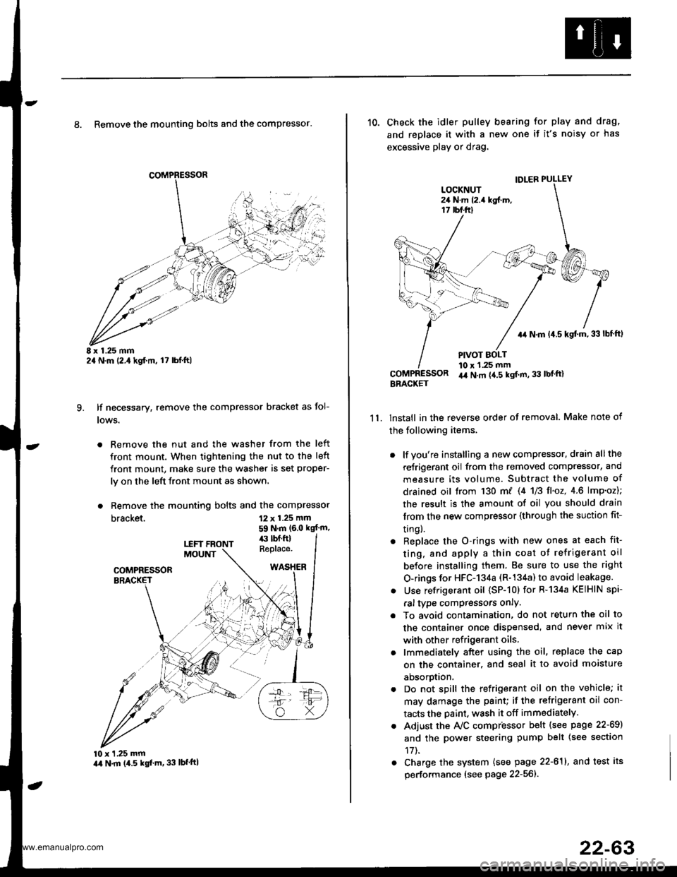
8. Remove the mounting bolts and the compressor.
E x 1.25 mm2a N.m (2.,1kgf.m, l7 lbl.ft)
lf necessary, remove the compressor bracket as fol-
lows.
. Remove the nut and the washer from the left
front mount. When tightening the nut to the left
front mount, make sure the washer is set proper-
ly on the left front mount as shown.
. Remove the mounting bolts and the compressor
bracket.
q
12 x 1.25 mm
59 N.m (6.0 kgt'm,
10 x 1,25 mmart N.m (4.5 kgf'm, 33 lbfftl
11.
10. Check the idler pulley bearing for play and drag,
and replace it with a new one if it's noisy or has
excessive play or drag.
lnstall in the reverse order of removal. Make note of
the following items,
. lf you're installing a new compressor, drain all the
reJrigerant oil from the removed compressor, and
measure its volume. Subtract the volume of
drained oil trom 130 m/ 14 U3 fl'o2,4.6 lmp'oz);
the result is the amount of oil you should drain
lrom the new compressor (through the suction fit-
trngl.
. Replace the O-rings with new ones at each fit-
ting, and apply a thin coat o{ refrigerant oil
before installing them. Be sure to use the right
O-rings for HFC-134a (R-134a) to avoid leakage.
. Use refrigerant oil (SP-10) for R-134a KEIHIN spi-
ral type compressors only.
. To avoid contamination, do not return the oil to
the container once dispensed, and never mix it
with other refrigerant oils.
. lmmediately after using the oil, replace the cap
on the container. and seal it to avoid moisture
aDsorprlon.
. Do not spill the refrigerant oil on the vehicle; it
may damage the paint; if the retrigerant oil con-
tacts the Daint, wash it off immediately.
. Adjust the Ay'C compr'essor b€lt (see psge 22-69)
and the power steering pump belt {see section
17t.
. Charge the system (see page 22-611, and test its
performance (see page 22-56]-.
IDLER PULLEY
+r N.m 14.5 kgt m,33lbf ftl
PIVOT BOLT10 x 1.25 mmir4 N.m {4.5 kgt m, 33 lbl'ft}BBACKET
www.emanualpro.com
Page 1159 of 1395
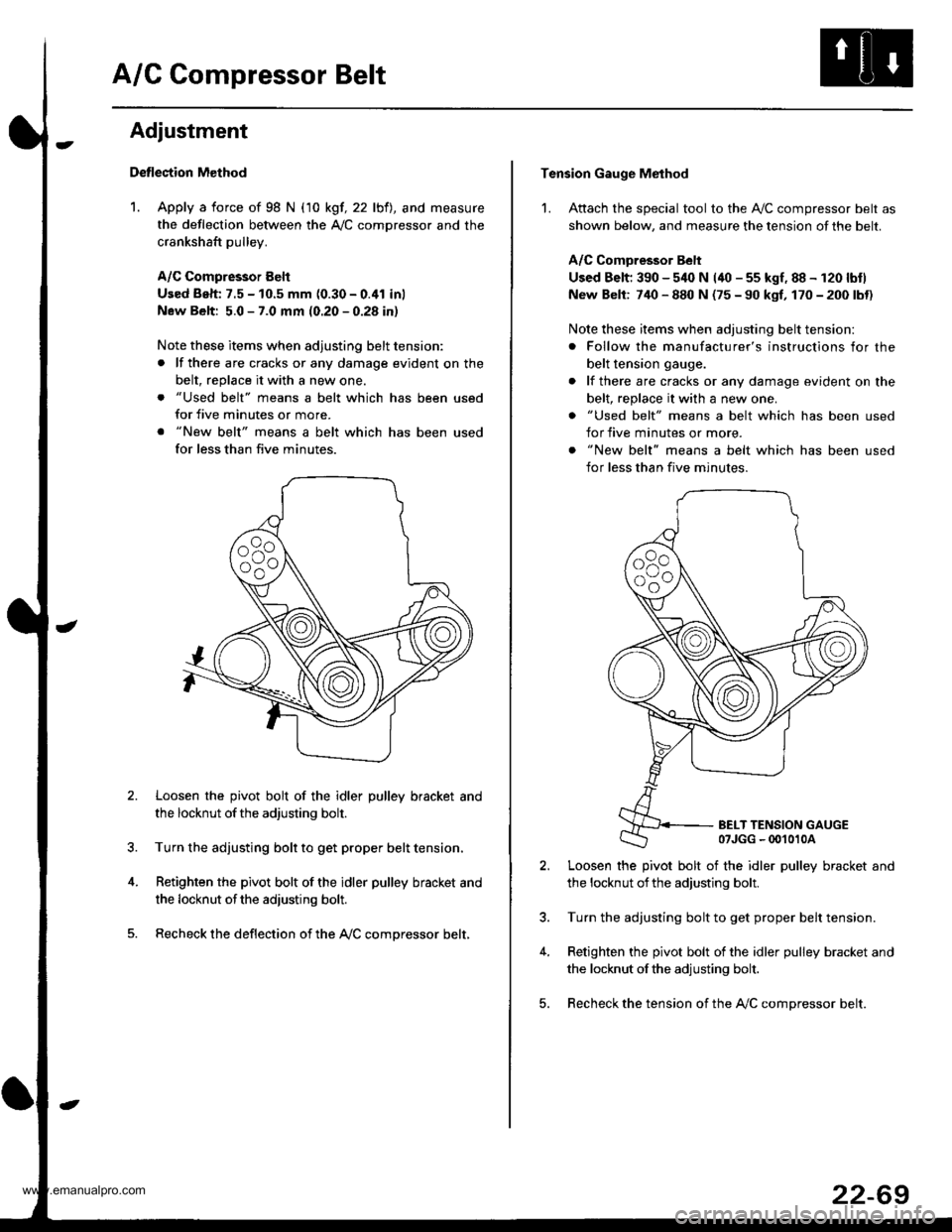
A/C Compressor Belt
Adjustment
Detlection Method
1. Apply a force of 98 N (10 kgf, 22 lbfl, and measure
the deflection between the A,/C comDressor and the
crankshaft pulley.
A/C Compressor Eelt
Used Beh: 7.5 - 10.5 mm (0.30 - 0.41 inl
New Belt: 5.0 - 7.0 mm (0.20 - 0.28 in)
Note these items when adjusting belt tension:
. lf there are cracks or any damage evident on the
belt, replace it with a new one.
. "Used belt" means a belt which has been used
for five minutes or more.
. "New belt" means a belt which has been used
for less than five minutes.
Loosen the pivot bolt of the idler pulley bracket and
the locknut ofthe adjusting bolt.
Turn the adjusting bolt to get proper belt tension,
Retighten the pivot bolt of the idler pulley bracket and
the locknut ofthe adiusting bolt.
Recheck the deflection of the A,/C compressor belt,
Tension Gauge Method
1. Attach the special tool to the Ay'C compressor belt as
shown below, and measure the tension of the belt.
A/C Comoressor Belt
Used Belt; 390 - 540 N (40 - 55 kgf, 88 - 120 lbtl
New Belt: 740 - 880 N (75 - 90 kgf, 170 - 200 lbt)
Note these items when adjusting belt tension:
. Follow the manufacturer's instructions for the
belt tension gauge.
. lf there are cracks or any damage evident on the
belt, replace it with a new one.
. "Used belt" means a belt which has been used
for five minutes or more.
. "New belt" means a belt which has been used
for less than five minutes.
BELT TENSION GAUGE07JGG - 00't010A
Loosen the pivot bolt of the idler pulley bracket and
the locknut ofthe adjusting bolt.
Turn the adjusting bolt to get proper belt tension.
Retighten the pivot bolt of the idler pulley bracket and
the locknut ofthe adjusting bolt.
Recheck the tension of the A,/C compressor belt.
22-69
www.emanualpro.com