Page 210 of 1395

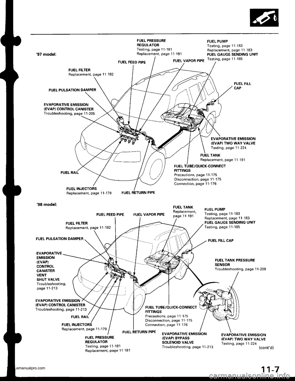
FUEL PRESSUREREGULATORTesting, page 11-181Replacement, page 11 181
FUEL PUMPTesting, page 11 183Replacement, page 11 183FUEL GAUGE SENDING UNITTesting, page 11 185
'97 model:
'98 model:
FUEL PULSATION DAMPER
EVAPORATIVE EMISSIONIEVAP) CONTROL CANISTERTroubleshooting. page 1'l-205
FUEL FILTERReplacement, page 11 182
FUEL INJECTORSReplacement, page 1 1-179
FUEL FEED PIPEFUEL VAPOR PIPE
FUELFITTINGS
FUEL FILLCAP
EVAPORATIVE EMISSION
IEVAPI TWO WAY VALVETesting, page 11 224
TANKReplacement, page 11 191
-CONNECT
Precautions, page 1 1-175Disconnection, page 11 175Connection, page 1 1-176
FUEL FILTERReplacement, page 11 182
FUEL FEED PIPEFUEL VAPOR PIPE
FUEI- TANKReplacement,page 1l 191
FUEL TUBE/OUICK.CONNECTFITTINGSPrecautions, page 11 '175
Disconnection, page 11 175Connection, page 11 176
FUEL PUMPTesting, page 11 183Replacement, page 11 183FUEL GAUGE SENDING UNITTesting, page 1l'185
FUEL FILL CAP
FUEL TANK PRESSURESENSORTroubleshooting, page 1 l-209
FUEL PULSATION DAMPER
EVAPORATIVEEMTSSTONIEVAPICONTROLCANISTERVENTSHUT VALVETroubleshooting,page 11'213
EVAPORATIVE EMISSIONIEVAPI CONTROL CANISTERTroubieshooting, page 1 1 -213
FUEL RAIL
FUELFeplacement, page 1 1-179
FUEL PRESSURENEGULATORTesting, page 11-181Replacement, Page 11 181
EVAPORATIVE EMISSION{EVAP) EYPASSSOLENOID VALVETroubleshooting, page 1 1'213
€VAPORATIVE EMISSION{EVAP) TWO WAY VALVETesting, page 11 224(cont'd)
www.emanualpro.com
Page 211 of 1395
Gomponent Locations
Index lcont'd)
'99 - (X) modols:
FUEL TANKReplacement,page 11-191
FUEL FEED PIPE
FUEL FILTERReplacement, page 11 182
FUEL VAPOR PIPE
FUELFITTINGS
FUEL PUMPTesting, page '11 183Replacement, page 1 1_183FUEL GAUGE SENDING UNITTesting, page 11-185
FUEL FILL CAP
EVAPORATIVE EMISSIONIEVAP) CONTROLTroubleshooting, page 1 1-213
FUEL PULSATION DAMPER
FUEL RAIL
FUELReplacement, page 1 1-179
EVAPORATIVEEMtSStON
IEVAP)CONTROLCANISTERVENTSHUT VALVETroubleshooting,page 11-213FUEL TANK PRESSURESENSORTroubleshooting, page 1'l'208
EVAPORATIVE EMISSION{EVAP) TWO WAY VALVETesting, page 11-224
FUEL PRESSUREREGULATORTesting, page 11-181Replacement, page 11 181,CONNECT
PrecaLrtions, page 1 1-175Disconnection, page 1 1-175Connection, page 176
EVAPORATIVE EMISSION{EVAPI BYPASSSOLENOID VALVETroubleshooting, page 11 213
www.emanualpro.com
Page 381 of 1395
Fuel Injectors
R6placomoni
1. Relieve the fuel pressure (see page 11-178).
2. Remove the resonato. chamber ('99 - 00 models).
O.RINGBeplace.
Disconnect the connectors from the fuel injectors, and disconnect the IAT sensor 2P connector ('97 - 98 models) and
EVAP purge control solenoid valve 2P conn€ctor ('97 - 98 models),
Disconnect the PCV valve and the vacuum hose from the fuel pressure regulator.
Place a shop towel over the fuel return hose, then disconnect it from the fuel pressure regulator.
Remove the retainer nuts on the fuel rail.
Disconnect the fuel rail.
7, Remove the fuel injectors from the intake manifold.
'97 - 98 model3:
EVAP PURGE CONTROLSOLENOID VALVE 2P CONNECTORIAT SENSOR
FUEL PULSATION2P CONNECTOR
12 N.m{1.2 kgt'm,8.7 tbtft)
FUELPRESSUREREGULATOR
O.RING
FUELPRESSUREREGULATOR
CUSHION
O.RINGReplace.
CUSHIONRINGReplace.
SEALRINGReplace.
Replace.
SEALRINGReplace.
S
11-179
www.emanualpro.com
Page 382 of 1395

Fuel Supply System
Fuel Injectors {cont'dl
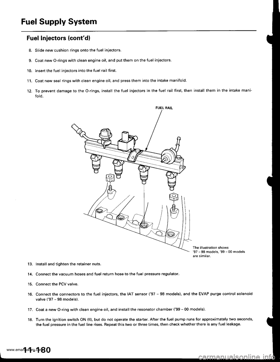
8. Slide new cushion rings onto the fuel injectors.
9, Coat newO-ringswith clean engine oil,and putthem onthefuel iniectors.
'10. lnsert the fuel injectors into the fuel rail first.
11. Coatnewseal ringswithclean engineoil,and press them into the intake manifold
12. To prevent damage to the O-rings, install the fuel injectors in the fuel rail first, then install them in the intake mani-
fold.
FUEL RAIL
The ill!stration shows'97 -98 models,'99 - 00 modelsare similar.
13. lnstall and tighten the retainer nuts.
14. Connect the vacuum hoses and fuel return hose to the fuel pressure regulator.
15. Connect the PCV valve.
16. Connect the connectors to the fuel injectors, the IAT sensor ('97 - 98 models), and the EVAP purge control solenoid
valve {'97 - 98 models).
Coat a new O-ring with clean engine oil, and install the resonator chamber ('99 - 00 models).
Turn the ignition switch ON (ll), but do not operate the starter. After the fuel pump runs for approximately two seconds,
the fuef pressure in the fuel line rises. Repeat this two or three times, then check whether there is any fuel leakage.
11.
18.
1 1-180
www.emanualpro.com
Page 1089 of 1395
POlNTx.y / I
'sad
POINT m3, m4
Upper Arm
M12 x P1.25
Locate Hole
POINT 3, s1
o14 {0.551 For Trailing Aim
POINT v
Fuel Tank Strap Poinr
2700.5 (106.32)SECTION BBRear Damoer Center
POINT n
FOINT
rg (0.3) Fuel TStrap Center
271,1(10,6.9)
o2010.8| Locate Hole
For Rear Cros3 Beam
For Reer Cross Beam
POINT w
Bear Damper LowerBushing Point
I
\-
ql
ol
.df
20-109
www.emanualpro.com
Page 1186 of 1395

Connector ldentification and Wire Harness Routing
Left Side Wire Harness
Connector oI
Terminal
Number of
CavitiesLocaiionConnects toNot6s
c551
c552
c554
c556
c558
c559
c559
c560
c562
c563
c563
c564
c565
c566
c568
c569
c570
c572
c573
c57 4
c575
c576
c578
c579
c580
c581
8
16
10
14'I
14
16
20
20
24
)
1
5
1
1
6
1
2
14
1
1
6
1
6
Behind under-dash fuse/relay box
Behind under-dash fuse/relay box
Left side of steering wheel
Left side of steering wheel
Left side of steering wheel
Above under-dash fuse/relay box
Above under-dash fuse/relay box
Driver's door
Behind left kick panel
Behind left kick panel
Behind left kick panel
Left side offloor
Left quaner panel
Fueltank
On left half of rear cross beam
On left half of rear cross beam
Left quarter panel
Left quarter panel
Left quarter panel
Left quarter panel
Left quarter panel
Left quarter panel
On left half of rear cross beam
Right quarter panel
Right quarter panel
Left quarter pillar
Left side of floor
Left B-piller
Left B-piller
Behind left kick panel
Behind left kick panel
Under left side of dash
Left B-piller
Fueltank
Left side of steering wheel
Under-dash fuse/relay box (C921)
Under-dash fuse/relay box (C923)
Power mirror switch
Power window master switch
Power window master switch
Dashboard wire harness {C505)
Dashboard wire harness 1C505)
Driver's door wire harness (C661)
Main wire harness (C403)
Main wire harness (C404)
Main wire harness (C404)
Driver's seat belt switch
Left rear door switch
Fuel unit
Left rear ABS wheel sensor
Left rear ABS wheel sensor
Rear accessory socket connector {+}
Rear accessory socket connector (-)
Rear bumper wire harness 1C641)
Trailer lighting connector
Tailgate door latch switch
Left rear speaker
Right rear ABS wheel sensor
Rear wire harness (C611)
Right rea. door switch
Left taillight
Parking brake switch
Left rear door wire harness (C681)
Driver's door switch
Select unlock relay (for security alarm
system)
Junction connector (for power door
locks)
SRS main harness (C807)
Driver's seat belt tensioner
Fuel tank pressure sensor sub-harness(c645)
Power window master switch
'97 - 98
mooets'99 - 00
models
'97 model'98 - 00
models
Optional
'97 model'98 - 00
models
'98 - 00
mooets'98 - 00
models'98 - 00
mooets'99 - 00
mooets
G551
G553
Behind left kick panel
Left side ot floor
Left quarter piller
Body ground, via left side wire harness
Body ground, via left side wire harness
Body ground, via left side wire harness
23-26
www.emanualpro.com
Page 1208 of 1395
Ground Distribution
Ground-to-Component(sl Index (cont'dl
Wire ColorGround
G552
G501
G801
BLK
BLK
BLK
BLK
Component or Circuits Grounded
Audio unit
Driver's door lock actuator (door lock knob switch)
Driver's door lock switch
Driver's power window motor
Keyless door lock control unit ('98 - 00 models)
Power door lock control unit
Power mirror switch
Power window master switch
Driver's seat belt switch
Fuel gauge sending unit
Fuel pump (FP)
Left rear side marker light
Left taillight
Rear accessary socket
Right rear side marker light
Trailer lighting connector
High mount brake light
Rear window defogger
Rear window wiper motor
Rjght taillight- plus eveMhing grounded through G631
Hatch glass opener solenoid
License plate light- plus eveMhing grounded through G6l1
SRS unit
BLK
BLK
BLK
23-48�
www.emanualpro.com