Page 912 of 1395
Front Suspension
31.
Knuckle/Hub Replacement (cont'dl
Wash the knuckle and hub thoroughly in high flash
point solvent before reassembly,
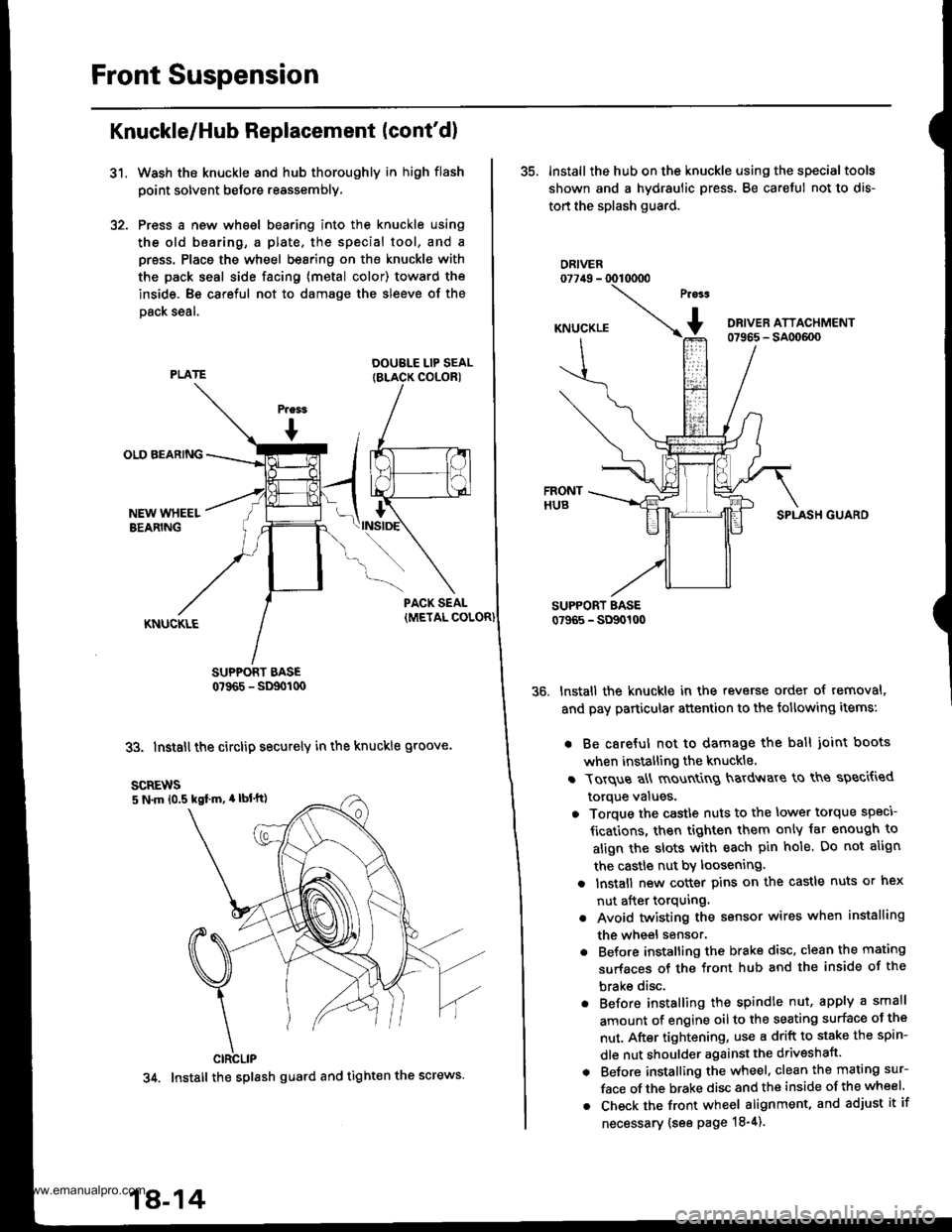
Press a new wheel bearing into the knuckle using
the old b6aring, a plate. the special tool, and a
press. Place the wheel bearing on the knuckle with
the pack seal side facing (metal color) toward the
inside. Be careful not to damage the sleeve of the
Dack seal.
DOUBLE LIP SEALIBLACK COLORI
SUPPORT BASE0?965 - SD90t00
33. Install the circlip securely in the knuckle groove.
35. lnstall the hub on the knuckle using the specialtools
shown and a hydraulic press. Be careful not to dis-
tort the splash guard.
ORIVER077irg - 0010000
SPLASH GUARO
lnstall the knuckle in the reverse order of removal,
and pay particular attention to the following items:
. Be careful not to damage the ball joint boots
when installing the knuckle.
r Torque a\ mount
g hardv{are to ths speci{ied
torque values,
o Torque the castle nuts to the lower torque speci
fications, then tighten them only iat enough to
align the slots with each pin hole. Do not align
the castle nut by loosening.
a lnstall new cotter pins on the castle nuts or hex
nut after torquing.
. Avoid twisting the sensor wires when installing
the wheel sensor.
. Before installing the brake disc, clean the mating
surfaces of the front hub and the inside of the
brake disc.
. Before installing the spindle nut, apply a small
amount of engine oil to the seating surface oJ the
nut. After tightening, use a drift to stake the spin-
dle nut shoulder against the driveshaft.
. Before installing the wheel. clean the mating sur-
face of the brake disc and the inside of the wheel.
. Check the front wheel alignment, and adjust it if
necessary {see page 18-4).
scREws5 N.m 10.5 kgl m, 4 lbl'tt)
CIRCLIP
34. Install the splash guard and tight€n the screws.
18-14
www.emanualpro.com
Page 913 of 1395
'1.
Lower Ball Joint Replacement
Remove the knuckle (see page 18-10).
Remove the boot by prying the set ring off.
Check the boot for deterioration and damage. and
replace it if necessary.
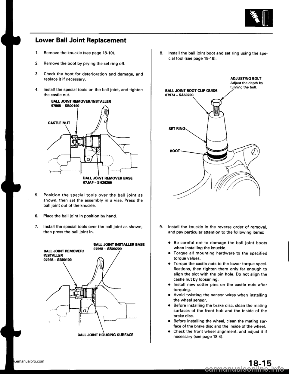
lnstall the special tools on the ball joint, and tighten
the castle nut.
BAII JOINT BEMOVER BASE07JAF - SH2oe00
Position the special tools over the ball joint as
shown. then set the assembly in a vise. Press the
ball joint out of the knuckle.
Place the ball joint in position by hand.
Install the special tools over the ball joint as shown,
then press the balljoint in.
BAII JOINT INSTAL1IR BASE
7.
8AI.I JOINT REMOVEN/INSTALLER
BALL JOINT HOUSING SURFACE
18-15
8. Install the ball joint boot and set ring using the spe-
cial tool {see page 18-16}.
Install the knuckle in the reverse order of removal.
and pay particular attention to the following items:
. Be careful not to damage the ball joint boots
when installing the knuckle.
. Torque all mounting hardware to the specified
toroue values.
a Torque the castle nuts to the lower torque speci-
fications, then tighten them only far enough to
align the slot with the pin hole. Do not align the
castle nut by loosening.
. Install new cotter pins on the castle nuts after
IOrqurng.
Avoid twisting the sensor wires when installing
the wheel sensor.
Before installing the brake disc, clean the mating
surfaces of the front hub and the inside of the
brake disc.
Before installing the wheel. clean the mating sur-
face of the brake disc and the inside of the wheel.
Check the front wheel alignment, and adjust it if
necessary (see page 18-4).
o
www.emanualpro.com
Page 923 of 1395
Reassembly
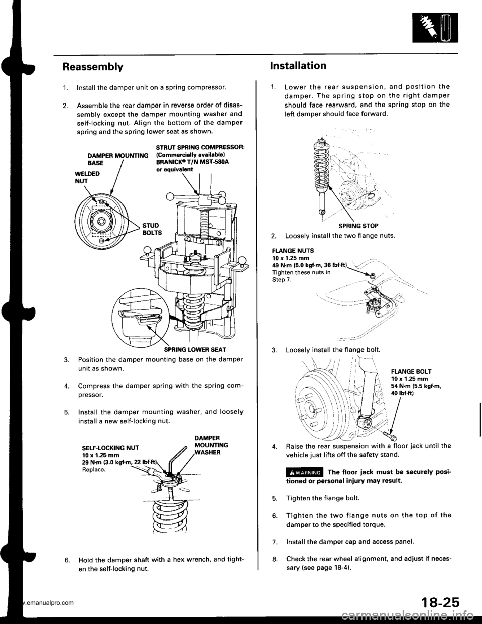
1.Install the damper unit on a spring compressor,
Assemble the rear damper in reverse order of disas-
sembly except the damper mounting washer and
self-locking nut. Align the bottom of the damper
spring and the spring lower seat as shown.
2.
DAMPER MOUNNNG
STRUT SPBING COMPRESSOR:(Commorcislly !v.ilablelBRANICKC T/N MST.s8OA
3.Position the damper mounting base on the damper
unit as shown.
Compress the damper spring with the spring com-
pressor.
Install the damper mounting washer, and loosely
install a new self-locking nut.
SELF.LOCKING NUT10 x 1.25 mm29 N.m (3.0
Replace.
Hold the damper shaft with a hex wrench, and tight-
en the self-locking nut.
1.
lnstallation
Lower the rear suspenston,
damper. The spring stop on
should face rearward, and the
left damper should face forward.
and position the
the right damper
sprang stop on the
SPRING STOP
2. Loosely install the two flange nuts.
FLANGE NUTS10 x 1.25 mm . .:{9 N.m 15.0 kgf.m, 36 lbtft}- :',,-rigf't"n if'"""_nrr. in ----.-*
qla^ 7Step 7.
3. Loosely install the flange bolt.
FLANGE EOLT10 x 1.25 mm54 N.m 15.5 kgt.m,40 tbI.ft)
6.
7.
8.
Raise the rear suspension with a floor jack until the
vehicle just lifts off the safety stand.
@ The floor iack must be securely posi-
iioned or personal iniury may result.
Tighten the flange bolt.
Tighten the two flange nuts on the top of the
damper to the specified torque.
Install the damper cap and access panel.
Check the rear wheel alignment. and adjust if neces-
sary (see page 18-4).
18-25
www.emanualpro.com
Page 925 of 1395
Brakes
Special Tools ............. 19-2
Component Locations
lndex ................ ...... 19-3
Inspection and Adlustment
Brake System Rubber Parts
and Brake Booster ..........,,,.......... 19-4
Brake Pedal ............ 19-5
Parking Brake ........ 19-6
Bleeding ................. 19'7
Brake System Indicator ................... 19-8
Front Brake Pads
Inspection and Replacement .......... 19-9
Front Brake Disc
Disc Runout Inspection ................... 19-11
Disc Thickness and
Parallelism Inspection ........,........ 19-1 1
Front Brake Caliper
Disassembly/Reassembly ............... 19-12
Master Cylinder/Brake Booster
Removal/lnstallation ....................... 19-13
Master Cylinder
Inspection/Disassembly .............. 19-14
Pushrod Clearance Adiustment ...... 19-14
Brake Booster Inspection ...,.,,,,....... 1 9-1 5
Rear Drum Brakes
Inspection .............. 19-15
Brake Shoes
Replacement ..... 19-r 8
Wheel Cylinder Replacement ......... 19-20
Brake Hoses/Lines
Inspection/Torque Specifications ... 19-21
Hose Replacement ....,...,............. ..,,, 19-22
Parking Brake Cable
Inspection and Replacement .......... 19-23
www.emanualpro.com
Page 927 of 1395
Gomponent Locations
lndex
ERAKE SYSTEM INOICATORCircuit Diagram, page't9-8
PARKING BRAKEAdjustment, page 19-6Parking Brake Switch Test, page '19-8
PARKING BRAKE CABI..EInspection and Replacement,page 19-23
BRAKE BOOSTERBrake Booster Inspection, page 19-15
Removal/lnstallation, page 19 13
MASTER CYLINDER
Inspection, pago 19-16Brake Shoes Replacement,page 19-18Wheel CylinderReplacement, page 19-20
REAR DRUM BRAKE
Removal/lnstallation, page 19-13lnspection/Disassembly.page 19-14Pushrod Clearance Adjustment,page 19 ldBrake Fluid LevelSwitch Test,page 19-8
Inspection/Torque Specification, pag€'19-21
Hose Replacement, Page 19-22
Front Brake Pads, page 19-9Front Brake Disc. page 19-11Front Brake Caliper, page 19-12
)i't ' -"''
/'"''t,'..,1 ...,. , \,,,.
i ,.'
'a.,
I
.) ..)
t ^fl)
19-3
www.emanualpro.com
Page 945 of 1395
Brake Hoses/Lines
Inspection/Torque Specif ications
1. Inspect the brake hoses for damage, deterioration, leaks, interference, and twisting
2. Check the brake Iines for damage, rusting, and leakage. Also check for bent brake lines.
3. Check for leaks at hose and line joints and connections, and retighten if necessary.
4. Checkthe master cylinder, proportioning control valve. and ABS modulator unit for damage and leakage.
NOTE: Replace the brake hose clip whenever the brake hose is serviced.
MASTER CYLINOER.Io.BRAKE LINE15 N.m 11.5 kgt m, 11 lbnftl
PROPORTIONING CONTROL VALVE.Io-BRAKE LINE15 N.m (1.5 kgf.m. 11 lbl.ftl
BRAKE LINE-Io-BRAKE HOSE15 N.m 11.5 kgd.m, 11 lbf'ft)
CYLINDER15 N.m 11.5 kgf.m, 11 lbf.ft)BLEED SCREW7 N.m 10.7 kgf.m, 5 lbt.fttBRAKE HOSE-to-CALIPER{8ANJO BOLTI34 N.m (3.5 kgf.m,25 lbf.ftlBLEED SCREW9 N.m 10.9 kgf.m, 6.5 lbf.ftlwith ABS:
19-21
www.emanualpro.com
Page 1091 of 1395
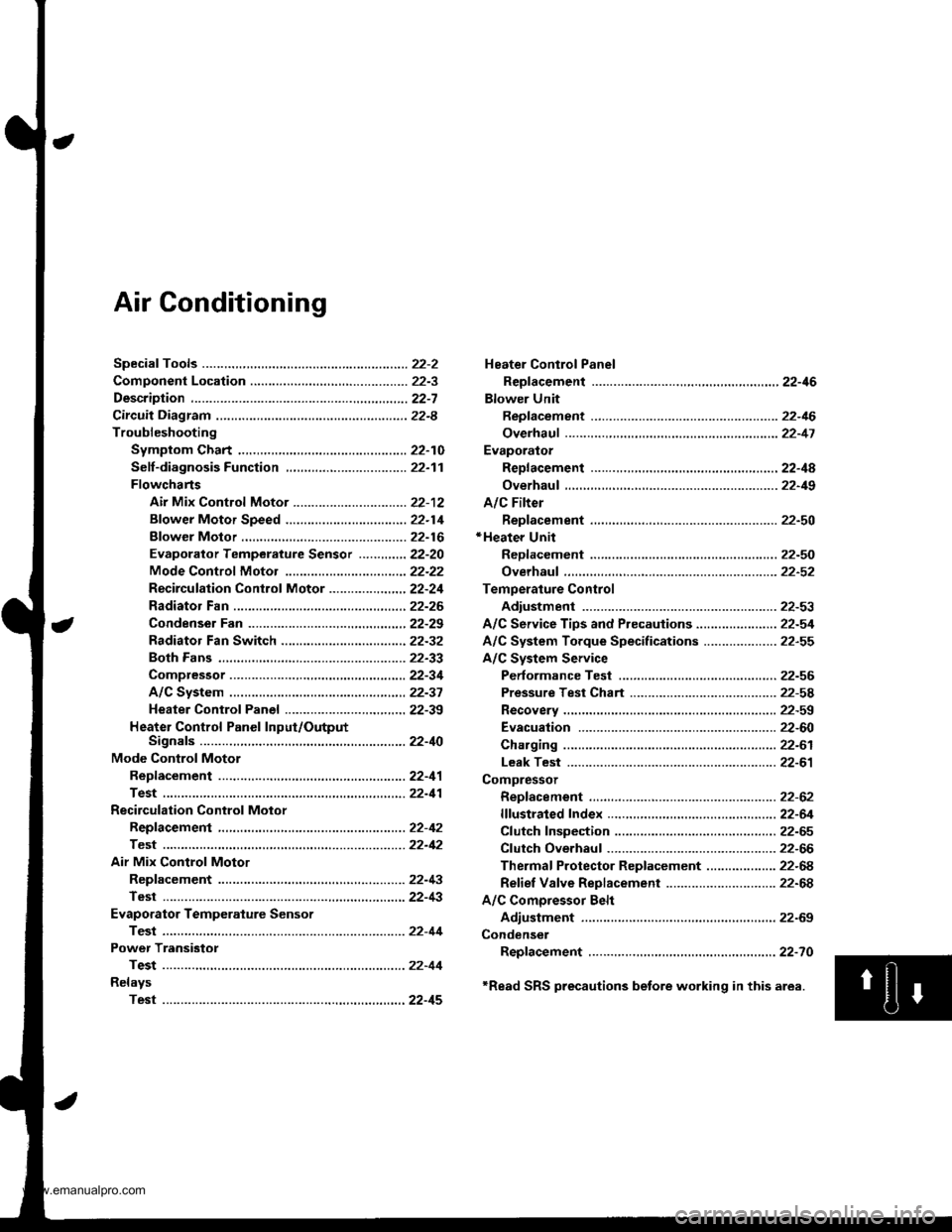
Air Conditioning
Heater Control Panel
Reofacement ,.,...,,.,..,.,.,,22-46
Blower Unit
Replacement .................. 22-46
Overhaul ...........,,,., .......-.22-17
Evaporalor
ReDlacement ...,.,.,..,......,22-4A
Overhaul ................ .........22-19
A/C Filter
Replacement ..................22-50*Heater Unit
ReDfacement ..................22-50
Overhaul ..,.,..,.,...,.. .........22-52
Temperature Control
Adiustment ....................22-53
A/C Service Tips and Precauiions............-....-.... 22-54
A/C System Torque Specifications .................... 22-55
A/C System Service
Performance Test ......,...22-56
Pressure Test Chart .-.....22-5a
Recovery ..............,. ...-.-...22-59
Evacuation -...........-........22-60
Charging ................ .......-.22-61
Leak Test ........................22-61
Compressor
Repfacement ..........-.......22-62
flfustrated Index .....,.......22-64
Cfutch fnspection .........,.22-65
Cfutch Overhaul ............- 22-66
Thermaf Protector Rep|acement ................... 22-68
Refief Valve Replacement .............................. 22-68
A/C Comoressor Belt
Adiustment .................... 22-69
Condenser
Repfacement .,.....,,.,..,.,..22-70
'Read SRS precautions betore working in this area.
www.emanualpro.com
Page 1145 of 1395
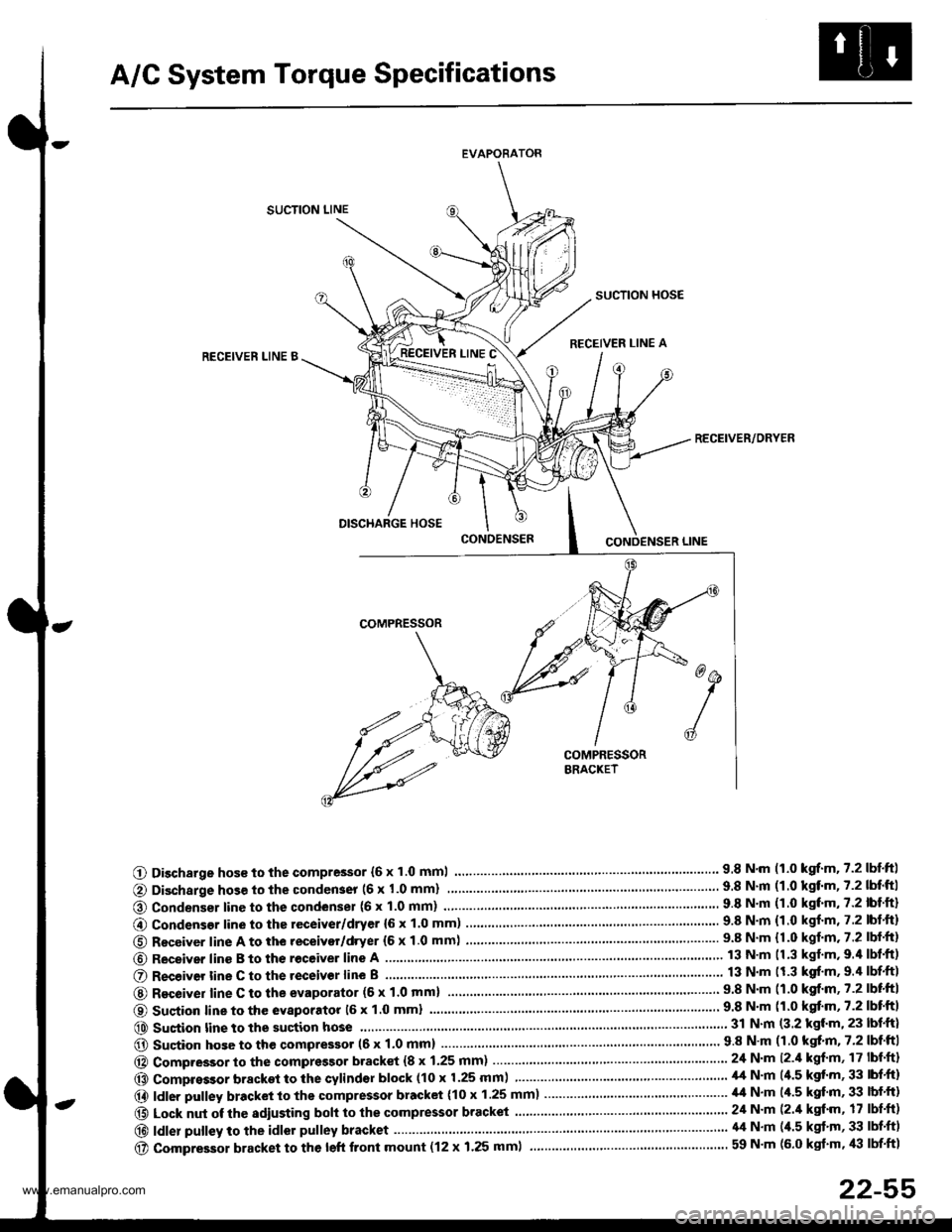
A/C System Torque Specifications
EVAPORATOR
SUCTION LINE
SUCTION HOSE
RECEIVER LINE ARECEIVEN LINE B
RECEIVER/ORYER
O Discharge hos€ to the compressor {6 x 1.0 mml.... 9.8 N.m 11.0 kgrf.m.7.2lbtftl
@ Condenser line to the condenser (6 x 1.0 mm)
@ Condensor line to the receiver/dryer {6 x 1.0 mm) ........9.8 N.m {1.0 kgf.m, 7.2 lbt.ft)
O Receiver line A to the receivor/dryer (6 x 1.0 mm) ...... ....................... 9.8 N.m {1.0 kgf.m.7.2 lbf.ft}
@ Receiver line B to th€ receive. line A
O R€ceiver tine C to the receivor line B
@ Recoiver line C to the evaporator (6 x 1'0 mml9.8 N'm (1.0 kgf.m,7.2lbtftl
O Sustion line to the evaporatot 16 x 1.0 mml
@ Sustion line to the suction hose...... 31 N.m (3.2 kgl.m, 23 lbf.ft)
@ Sucion hose to the qompressor (6 x 1.0 mm) .....'...' 9 8 N'm (1 0 kgt'm, 7'2 lbf'ftI
@ Compressor to the compressor bracket {8 x 1.25 mm) ... 24 N.m l2.il kgf'm, 17 lbf'ft}
@ Compressor bracket to the cylindsr block (10 x 1.25 mm) ................ ......... il,t N'm (4.5 kgt'm, 33 lbf'ft)
@ ldler pulley bracket to the compressor bracket (10 x 1.25 mm)..................... ,14 N.m (/r.5 kgf'm, 33 lbf'ft)
@ Lock nut of the sdiusting boh to the compressor bracket ......................... 24 N'm (2./t kgt'm, 17 lbf'ft)
@|d|erpu||eytotheid|orpu||eybracket.....'..........................'....\
.'.....'........'....44N.m(4.5kg''m'33|bf.f)
@ compressor bracket to the left front mount (12 x 1.25 mml ................... ............................ 59 N'm (6.0 kgt'm, /l:| lbf'ft1
22-55
www.emanualpro.com