Page 413 of 1395
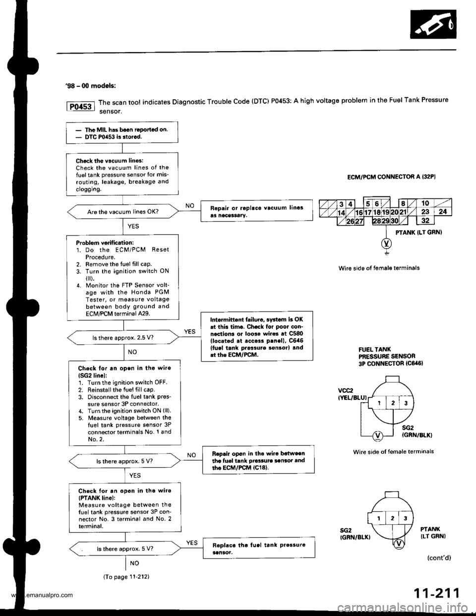
'98 - 00 modals:
The scan tool indicates Diagnostic Trouble Code (DTC) P0453: A high voltage problem in the Fuel Tank Pressure
sensor.
ECM/PCM CONNECTOR A {32PI
Wire sido ot fema16 t€rminals
FUEL TANXPf,ESSUBE SENSOR3p CONNECTOR {C6,a6l
vcc2IYEL/BLUI
sG2IGRN/BLKI
sG2(GRN/BLK}
Wire side ot female terminals
PTANKILT GRNI
(cont'd)
11-211
PTANK ILT GRN)
123
Thc MIL has b6on ropottcd on.DTC mia53 is dorcd.
Ch6ck tho vacuum linos:Check the vacuum lines of the
fuel tank pressure sensor lor mis-
routing, leakage, breakage and
cloggrng.
Are the vacuum lines OK?
Problorn verif ication:1. Do the ECM/PCM ResetProcedute.2. Remove the fuel fill cap.
3. Turn the ignition switch ON
{[).4. Monitor the FTP Sensor volt-age with the Honda PGM
Tester, or measure voltagebetween body ground and
ECM,PCM terminal429.Intarmittent tailuro, sv3iom b OKat this timo. Chock for poor con-nection3 or loo$ wire3 at C580(locstod .t .cc$r p.nell, C6a6(fucl tank pros3ure son3orl and.t the ECM/FCM.
ls there approx. 2.5 V?
Check lor an open in tho wiro
lSG2lin6l:1. Turn the ignition switch OFF.
2. R6installthe Iuel fill cap.3. Disconnect the Iu6l tank pres_
sure sensor 3P connector,4. Turn the ignition switch ON (ll).
5. M€asure voltago between thetuel tank pressure sensor 3P
connector terminals No. '! andNo.2.
Replir op€n in th. wi.c b€{weentha fuel tank Dio'sute sansot andtho EC|,/PCM {Cl8}.ls there approx. 5 V?
Ch€ck for an opon in tho wiro(PTANK linel:Measure voltage between thefuel tank pressure sensor 3P con-nector No. 3 terminal and No. 2terminal.
ls there approx. 5 V?
\To page 11-212)
www.emanualpro.com
Page 415 of 1395
'98 - 00 models:
The scan tool indicates Diagnostic Trouble code (DTC) P1456: Evaporative Emission (EVAP) control system leak
detected {fuel tank system).
Troubleshooting Flowchart
- The MIL has been reported on.- DTC P1456 is stored.
Check the fuel fill cap:Check the fuel fill cap (the caP
must be a gray OEM cap and be
tightened at least three "clicks" toproperly seal the system)-
ls the proper fuel fill cap installed
and properly tightened?Replace or tighton the cap.
Check the lueltill cap seal:
Check the fuel fill cap seal.
Replace the luelfiller pipe.ls the tuel filler pipe damaged?
Fuel till caD is OK. Do the luel
tank pressure Sensor test (see
page 11-2111. (EVAP Purge con-
trol solenoid valve t€sl (see Page11-2151.1r':'99 - 00 models
(cont'd)
11-213
www.emanualpro.com
Page 421 of 1395
'98 - 00 mod€ls:
The scan tool indicates Diagnostic Trouble code (DTc) P1457: Evaporative Emission (EVAP) Control system leak
detected (EVAP control canister system).
Troubl6shooting Flowchart('98 model only)_]
I
- The MIL has been rePorted on.- DTC P1,157 is storod.
Do the fuel tank Pressure sensor
test {see page 11-214).
ls the {ueltank pressure sensor OK?
Do the EVAP Purge contlol
solenoid valve test lsea Page 1l_
220t.
(cont'dl
11-219
www.emanualpro.com
Page 572 of 1395
Troubleshooting Procedures
Checking ths Diagnostic Trouble Code (DTC)
with an O8D ll Scan tool or Honda PGM Tsster
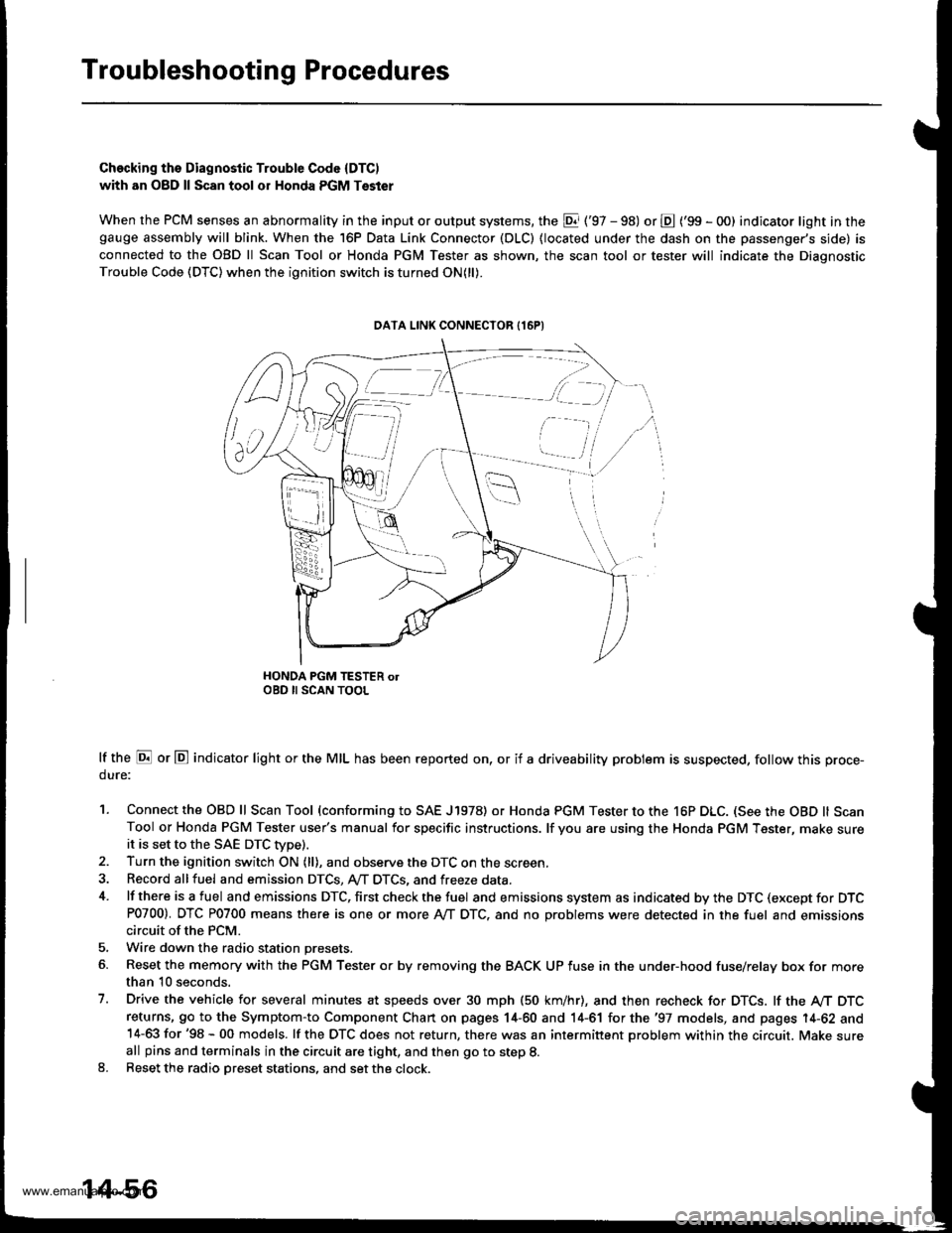
When the PCM senses an abnormality in the input or output systems, the El ('97 - 98) or E ('99 - O0) indicator light in thegauge ass€mbly will blink. When the 16P Data Link Connector (DLC) {located under the dash on the passenger's side) is
connected to the OBD ll Scan Tool or Honda PGM Tester as shown, the scan tool or tester will indicate the Diagnostic
Trouble Code (DTC) when the ignition switch is turned ON(ll).
HONDA PGM TESTER olOBD II SCAN TOOL
lf the E or E indicator light or the MIL has been reported on, or if a driveability problem is suspected, follow this proce-
dure:
1. Connect the OBD ll Scan Tool (conforming to SAE J1978) or Honda PGM Tester to the 16P DLC. (See the OBD ll ScanTool or Honda PGM Tester user's manual for specific instructions. lf you are using the Honda PGM Tester, make sureit is set to the SAE DTC Wpe).2. Turn the ignition switch ON (ll), and observe the DTC on the screen
3. Record allfuel and emission DTCS, A,,/T DTCS, and freeze data.
4. lf there is a fuel and emissions DTC, first check the fuel and emissions system as indicated by the DTC (except for DTCP0700). DTC P0700 means there is one or more Ay'T DTC, and no Droblems were detected in the fuel and emissionscircuit of the PCM.
5. Wire down the radio station presets.
6. Reset the memory with the PGM Tester o. by removing the BACK UP fuse in the under-hood fuse/relay box for morethan 10 seconds.
7. Drive the vehicle for several minutes at speeds over 30 mph (50 km/hr), and then recheck for DTCS. lf the A/T DTCreturns, 9o to the Symptom-to Component Chart on pages 14-60 and 14-61 for the '97 models, and pages 14-62 and14-63 for '98 - 00 models. lf the OTC does not return, there was an intermittent problem within the circuit. Make sureall pins and terminals in the circuit are tight, and then go to step 8.8. Reset the radio Dreset stations, and set the clock.
DATA LINK CONNECTOR {16PI
[ -=.r,
ili,i /i,
v,., i
14-56
www.emanualpro.com
Page 573 of 1395
Checking the Diagnostic Trouble Code IDTCI
with the Servic€ Check Connestol and Special Tool
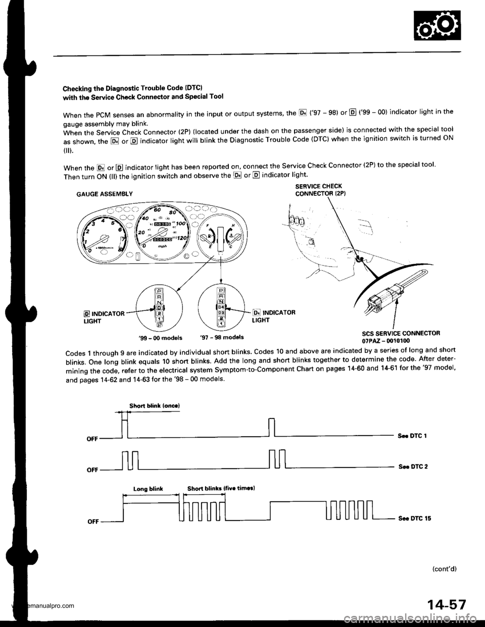
when the PcM senses an abnormality in the input or output systems' the E ('97 - 98) or E (gS - OO) indicator light in the
gauge assembly may blink.
When the Service Check Connector (2P) (located under the dash on the passenger side) is connected with the special tool
as shown, the E or E indicator light will blink the Diagnostic Trouble Code (DTC) when the ignition switch is turned ON
{ ).
when the E or E indicator light has been reponed on, connect the service check connector (2P) to the special tool
Then turn ON (ll) the ignition switch and observe the E or E indicator light'
.AUGE AssEMaLY $1,"^f:tT"'ff,
SCS SERVICE CONNECTOR07PAz - (x!l0100
codes 1 through 9 are indicated by individual short blinks. codes 1o and above are indicated by a series of long and short
blinks. one long blink equals 1o short blinks. Add the long and short blinks together to determine the code. After deter-
mining the code, refer to the electrical system symptom-to-component chart on pages 14-60 and 14-61 for the '97 model,
and pages 14-62 and 14-63 tor the '98 - 00 models.
Sr. DTC 1
S.. DTC 2
Long blinkShori blink! {fiv. timt l
Sc. DTC 15
(cont'd)
'99 - O0 models '97 - 98 models
Short blinl lonc.)
14-57
www.emanualpro.com
Page 577 of 1395
NOTE: When the OBD ll Scan Tool or Honda PGM Tester indicate DTC(s) for the automatic transmission control system'
the scan tool or tester indicates code P0700 simultaneously. code P07oo means a detection of some automatic transmis-
sion problem in the PGM-Fl control system
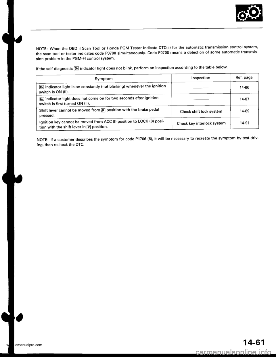
lf the self-diagnostic E indicator light does not blink, perform an inspection according to the table below.
NOTE: lf a customer describes the symptom for code P1706 (6), it will be necessary to recreate the symptom by test-driv-
ing, then recheck the OTC.
SymptomInspectionRef. page
E indicator light is on constantly (not blinking) whenever the ignition
switch is ON (ll).14-86
E indicator light does not come on for two seconds after ignition
switch is first turned ON (ll).
't 4-41
Shift lever cannot be moved from @ position with the brake pedal
Dressed,Check shift lock system14-89
lgnition key cannot be moved from ACC (l) position to LOCK {0) posi
tion with the shift lever in E position.Check keY interlock system14-91
14-61
www.emanualpro.com
Page 579 of 1395
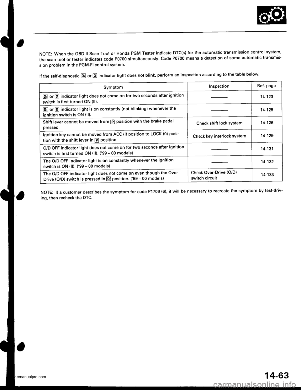
NOTE: When the OBD ll Scan Tool or Honda PGM Tester indicate DTC(S) for the automatic transmission control system,
the scan tool or tester indicates code P0700 simultaneously. Code P0700 means a detection of some automatic transmis-
sion problem in the PGM-Fl control system.
lf the self-diagnostic E or E indicator light does not blink, perform an inspection according to the table below.
NOTE: lf a customer describes the symptom for code P17OO (6), it will be necessary to recreate the symptom by test-driv-
ing. then recheck the DTC.
SymptomInspectionRef. page
E or E indicator light does not come on for two seconds after ignition
switch is first turned ON (ll).14-123
E or E] indicator light is on constantly (not blinking) whenever the
ignition switch is oN {ll).
14-125
Shift lever cannot be moved from E position with the brake pedal
presseo.Check shift lock system14-'t26
lgnition key cannot be moved from ACC (l) position to LOCK (0) posi-
tion with the shift lever in E position.Check key interlock system14-129
O/D OFF indicator light does not come on for two seconds after ignition
switch is first turned ON (ll). ('99 - 00 models)14-131
The O/D OFF indicator light is on constantly whenever the ignition
switch is ON (ll). ('99 - 00 models)14-132
The O/D OFF indicator light does not come on even though the Over-
Drive (O/Dl switch is pressed in E position. ('99 - 00 models)
Check Over-Drive {O/D}
switch circuit14-133
14-63
www.emanualpro.com
Page 948 of 1395

Anti-lock Brake System (ABSI,'97 - 00 Models
Special Tools ............. 19-26
Component Locations ......................... 19-27
Anti-lock Brake System (ABS)
Features/Construction ............. ......, 19-2A
Circuit Diagram ......... 19-32
ABS Control Unit Terminal
Arrangement ......... 19-34
Troubleshooting Precautions ............. 19-36
Diagnostic Trouble Gode (DTC)
Diagnostic Trouble Code (DTC)
Indication (SCS Model ................ 19-38
DTG Erasure (MES Mode) ............... 19-39
Troubleshooting lndex .................... 19-40
Troubleshooting
ABS Indicator Light Does Not
Come On ............ 19-41
ABS Indicator Light Does Not
Go Off (No DTC) ........................... 19-43
DTC 1r - 18:
Wheel Sensor .... 19-45
DTC 31 - 38:
Solenoid ............. 19-47
DTC 51 - 53:
ABS Pump Motor ......................... 19-49
DTC 54:
Main Relay ......... 19-52
DTC 61:
lgnition Voltage ........................... 19-54
DTC 81:
Central Processing Unit (CPU) .... 19-55
Modulator Unit
Removal/lnstallation ....................... 19-56
ABS Control Unit
Replacement ..,...... 19-57
Pulsers/Wheel Sensors
Inspection .............. 19-57
Wheel Sensor Replacement ............ 19-58
www.emanualpro.com