Page 334 of 1395
PGM-FI System
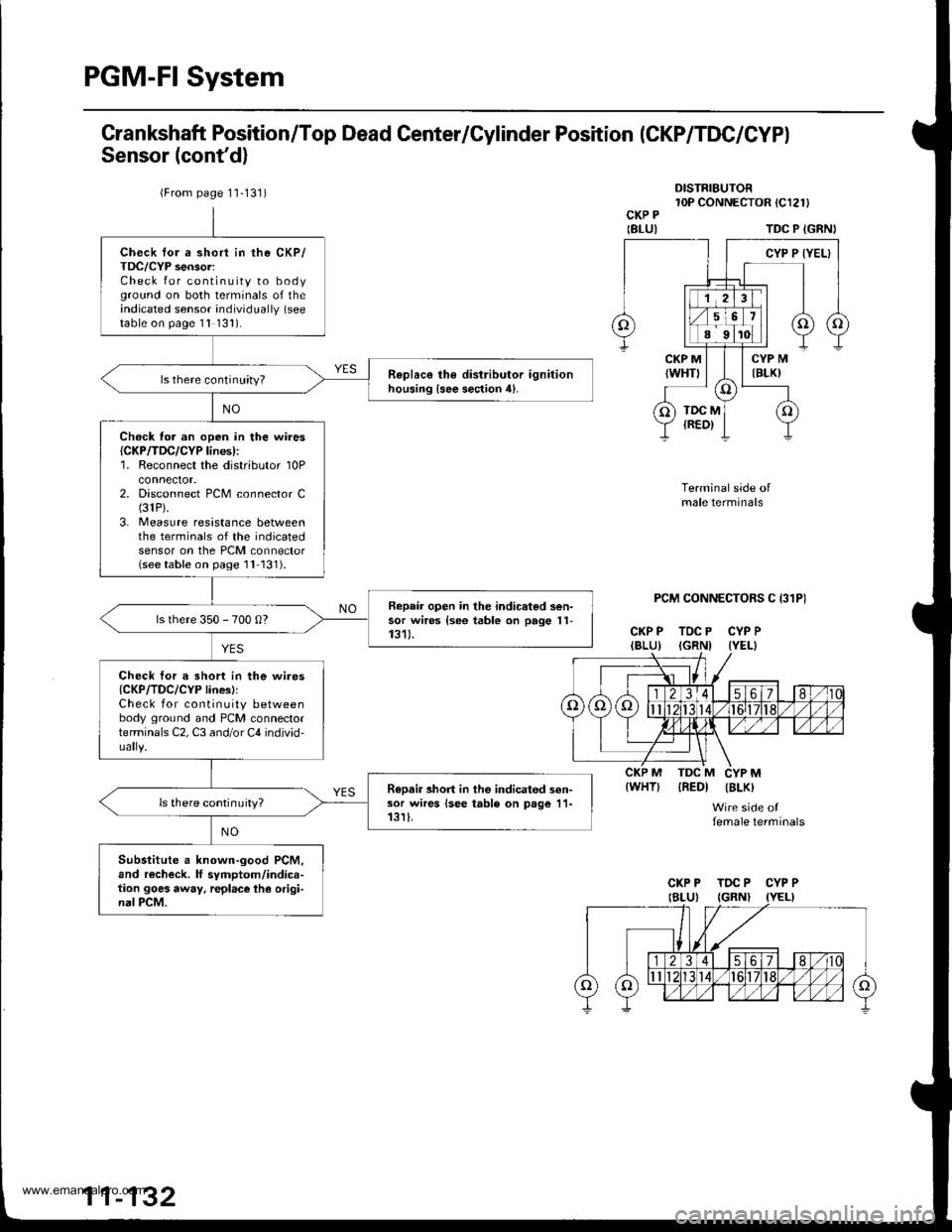
Grankshaft Position/Top Dead Center/Cylinder Position (CKP/TDC/CYPI
Sensor (cont'd)
DISTRIBUTOR10P CONNECTOR tCl2l)CKP P
IBLUITDC P {GRNI
PCM CONNECTORS C I31P)
CKP P TDC P CYP PIBLU) IGRNI IYEL}
Terminal side ofmale terminals
IREDI IBLK)
Wire side offemale terminals
{WHT)
{From page 1'1-131)
Check for a short in the CKP/TDC/CYP sensor:Check for continuity to bodyground on both terminals of theindicated sensor individually (see
table on page 1l 131).
R€plac€ the distributor ignitionhousing {see section 4}.ls there continuity?
Ch€ck fo. an open in the wires{CKP/TDC/CYP lines):'1. Reconnect the distributor 10Pconnector.2. Disconnect PCM connector C(31P).
3. Measure resistance betweenthe terminals of the indicatedsensor on the PCM connectorlseetable on page 1l 131).
Repair open in the indicated sen-sor wires {se6 table on page 11-131).ls there 350 - 700 0?
Check tor a short in the wires{CKP/TDC/CYP linesllCheck for continuity betweenbody ground and PCM connectorterminals C2, C3 and/or C4 individ-
R€Dair short in the indicatod sen-sor wires lsee table on page 11-13rI.ls there continuity?
Substitute a known-good PCM,and recheck. lf symptom/indica-tion goes away, r€place lhe origi-nal PCM.
CKP P TDC P CYP P
www.emanualpro.com
Page 336 of 1395
PGM-FI System
Grankshaft Position/Top Dead Center/Cylinder Position (CKP/TDC/CYPI
Sensor {cont'd}
(From page 11 133)
ECM/PCM CONNECTOR C {3IPI
Wire side of female terminals
Chock lor r 3hon in tho wirerICKP/TDC/CYP lin6):Check for continuity betweenbody ground and ECM/PCM con-nector terminals C8, C20 and/orC29 individually.
Rep.ir lhort in ths indicated son-aor wiroa 136o table on prge 11-133).
Substituto r known-good ECM/PCM, and .6chock. tf 3ymptom/indication goe3 swey, replrcetho original ECM/PCM.
11-134
www.emanualpro.com
Page 337 of 1395
![HONDA CR-V 1998 RD1-RD3 / 1.G Workshop Manual
Vehicle Speed Sensor (VSSI
lPosoo-]-. |posol l-
97 modol:
The scan tool indicates Diagnostic Trouble Code {DTC} P0500*�or P0501*r: A range/perfor-
mance in the Vehicle Speed Sensor (VSS) circuit. HONDA CR-V 1998 RD1-RD3 / 1.G Workshop Manual
Vehicle Speed Sensor (VSSI
lPosoo-]-. |posol l-
97 modol:
The scan tool indicates Diagnostic Trouble Code {DTC} P0500*�or P0501*r: A range/perfor-
mance in the Vehicle Speed Sensor (VSS) circuit.](/manual-img/13/5778/w960_5778-336.png)
Vehicle Speed Sensor (VSSI
lPosoo-]-'. |posol l-'
'97 modol:
The scan tool indicates Diagnostic Trouble Code {DTC} P0500*'�or P0501*r: A range/perfor-
mance in the Vehicle Speed Sensor (VSS) circuit. * I ; A/T*2i Mfi
FCM CONNECTORS
A t32Pl
LG1(BRN/BLK)
NOTE: Do not use the engine to turn thofront wheels with th6 rear wheels on theground. The 4WD system will engage andthe vehicle will suddenlv Iurch forward.
Wire side ot female terminals
LGl
{BRN/BLKI
(cont'd)
11-135
The MIL hes boen roported on.DTC m501 is 3tor€d.
Problom verificetion:1. Test'drive the vohicle.2. Check the vehicle speed withthe scan tool,
lntormittent tailure, rystom b OKat thia timo. Chock tor poor con-nection3 or 10o3o wires rt C129lvss) .nd rr rhe Pcfr4,
ls the correct speed indicated?
Chock for an open in tho PiCM:1. Turn the ignition switch OFF.2. Block the rear wheels and setthe parking brake.3. Jack up the lront of the vehicleand support it with saletystands.4. Turn the ignition switch ON (ll).
5. Elock the right front wheel andslowly rotate the left trontwheel by hand.6. Measure voltage betweenPCM connector terminals C18and A9.
Substitulc a known-good PCMand .och6ck. It symptom/indicd.tion go.a away, .cplaco tho origi-nel FCM.
Doesthe voltage pulse 0 Vand 5 V or battery voltage?
Check for a .hort in the PCM:L Turn the ignition switch OFF.2. Disconnect the PCM con'nector C (31P).
3. Turn the ignition switch ON (ll).
4. Elock the right front wheeland slowly rotate the left front
5. Measure vohage between PCMconnector terminals C18 andA9.
Substituto e known-good PCMand rochock. f rymptom/indica-tion goos rwry, roplsc. tho origi-nalFCM.
Doesthe voltage pulse 0 Vand 5 V or battery voltage?
- Repair short in the wirebetween the PCM lC18l,cruise control unit, speodo-meter, and VSS,- Repair opon in the wirebetween the PCM {C181 .ndrhe vss.- f wire is OK. tost lho VSS l3oosoction 231.
www.emanualpro.com
Page 338 of 1395
PGM-FI System
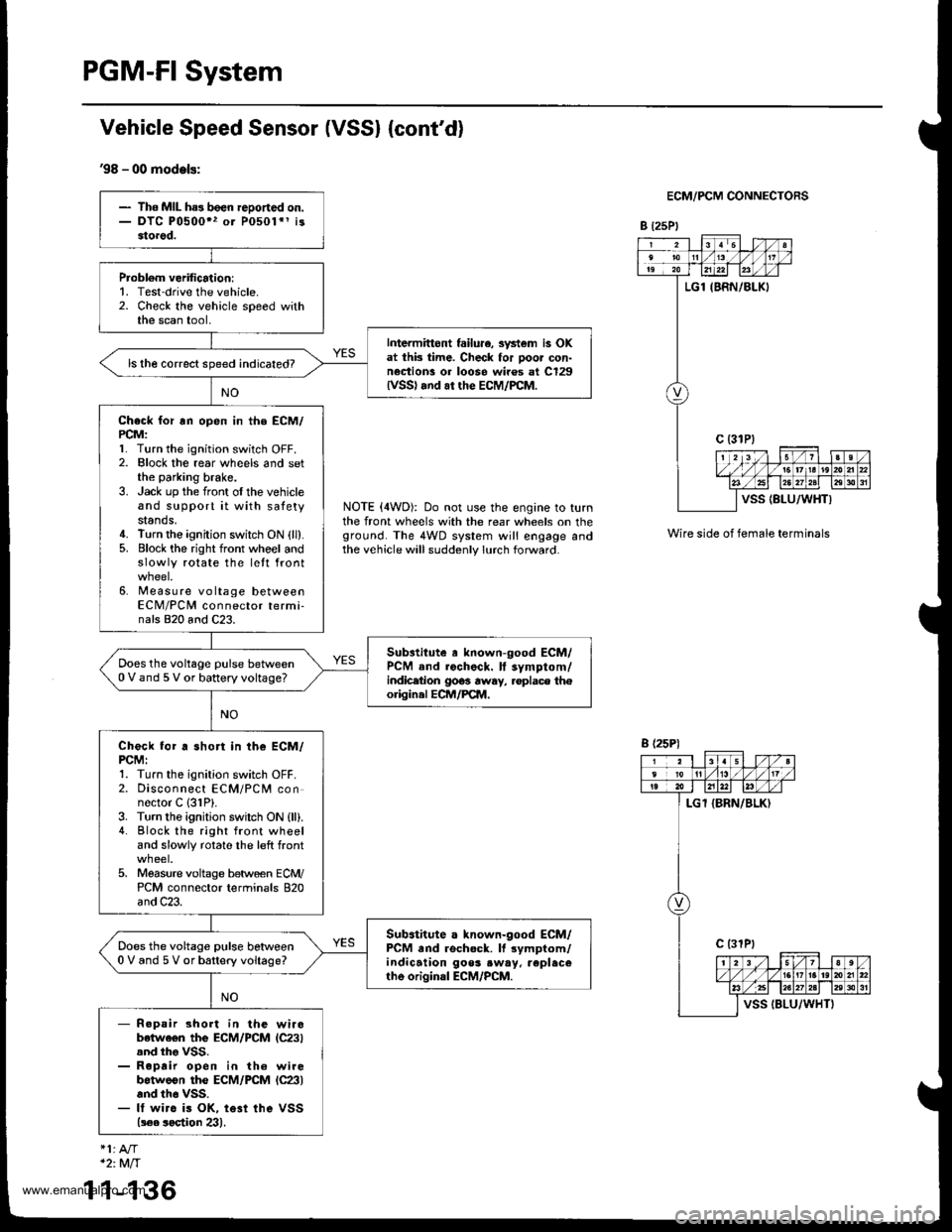
Vehicle Speed Sensor (VSSI {cont'd}
'98 - 00 models:
ECM/PCM CONNECTORS
B t25Pl
NOTE (4WD): Do not use the engine to turnthe front wheels with the rear wheels on theground. The 4WD system will engage andthe vehicle will suddenly lurch forward.
Wire side of female terminals
- The MIL ha3 been reDoned on.- DTC P0500" or P0501*1 i33torod.
Probl6m verification:1. Test-drive the vehicle.2. Check the vehicle speed withthe scan tool,
Intermittont failu.e, svstem is OKat thk time. Check for poor con-nection! or loose wiros at C129lvss) .nd ar the EcM/PcM.
ls the correct speed indicated?
Check for rn open in the ECM/PCM:l� Turn the ignition switch OFF.2. Elock the rear wheels and setthe parking brake.3. Jack up the front oI the vehicleand support it with satetystands.4. Turn the ignition switch ON {ll}.5. Block the right front whoel andslowly rotate the lett front
6. Measure voltage betweenECM/PCM connector termi-nals 820 and C23.
Substitute a known-good ECM/PCM and rochock. ll symptom/indicetion 9063 away, .oplace th€origin.l ECM/PCM.
Does the voltage pulse between0 V and 5 V or battery voltage?
Check for a short in the ECM/PCMI1. Turn the ignition switch OFF.2. Disconnect ECM/PCM connector C 131P).3. Turn the ignition swilch ON {ll).4. Block the right front wheeland slowly rotate the left front
5. Moasure voltage between ECM/PCM connector terminals 820and C23.
Sub.titute a known-good ECM/PCM and rschock. It rymptom/indication goos .w.y. replecerhe original ECM/PCM.
Does the voltage pulse betlveen0 V and 5 V or battery voltage?
- R.pair short in the wirobetwe€n the ECM/PCM lC23).nd tho VSS.- Roprir open in th6 wirebotweon the ECM/PCM lc23land th6 vss.- It wirc is OK, te3t ihe VSS(!€e soetion 23).
B (25P)
1
*2:Mft
1-136
www.emanualpro.com
Page 342 of 1395
PGM-FI System
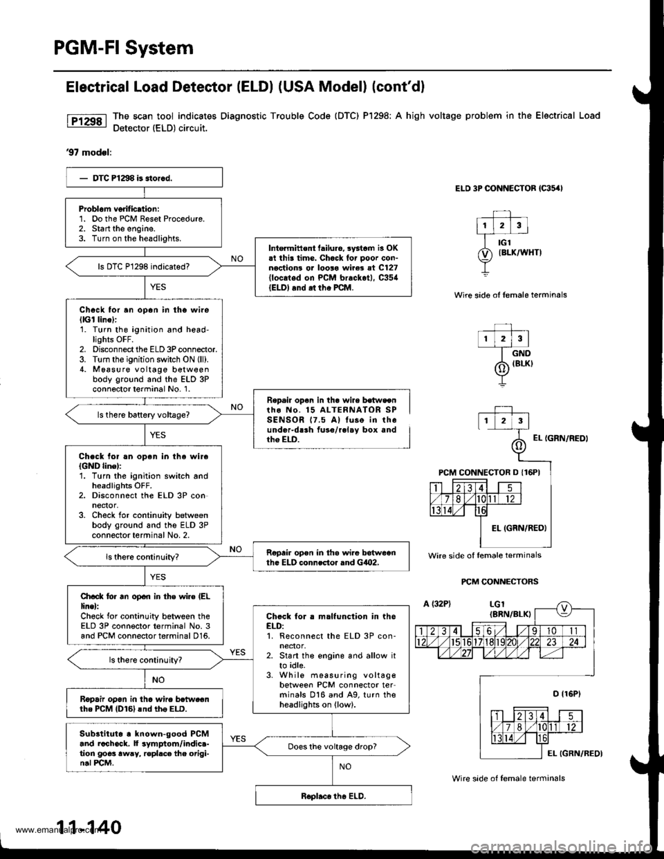
Electrical Load Detestor (ELDI (USA Model) (cont'dl
The scan tool indicates Diagnostic Trouble Code {DTC) Pl298; A high voltage problem in the Electrical Load
Detector (ELD) circuit.
97 modsl:
ELD 3P CONNECTOR {C35,'I
Wire sido oI lemale terminals
r lzlrl--T_ow
/6 IBLKI
Y
Repail op€n in th. wire b€tws€ntho No. 15 ALTERNATOR SPSENSOR 17.5 A) tuse in theunder-dlrh fuso/r.lay box andth6 ELD.EL {GRN/NEDI
PCM CONNECTORS
Problam verification:1. Do the PCM Reset Procedure.2. Start the engine.3. Turn on the headlights.Intermittent tailuro, systcm is OK.t this time. Chack for ooor con-noction! or looro wire3 at C127{locaied on PCM brackot), C35{{ELDI and .t tho PCM.
Chack for an opan in tho wilellGl linol:1. Turn thg ignition and head-lights OFF.2. Disconnect the ELD 3P connector.3. Turn the ignition switch ON {ll).4. M6asure voltage b€tw€enbody ground and the ELD 3Pconnoctor terminal No. 1.
Chock lol !n open in the wireIGND linel:'1. Turn the ignition switch andheadlights OFF.2. Disconnect the ELD 3P conneqor,3. Check for continuity betweenbody ground and the ELD 3Pconnector terminal No. 2.
Ropair opon in th6 wi.e betweonth. ELD connector rnd GiO2,
Ch.ck lo. an open in th€ wiro (EL
line):Check for continuity between theELD 3P connector terminal No. 3and PCM connector terminal 016.
Chock for . malfunction in theELD:1. Reconnect the ELD 3P con-neclor,2. Start the engine and allow itto idle.3. While measuring voltagebetween PCM connector terminals 016 and A9. turn theheadlights on (low).
ls there continuityT
R6pafu op6n in tho wire betweenthe PCM {D161snd th6 ELD.
Subltituto . known-good PCMand rachock, f symptom/indic.-tion goes awry, ropl.ce the origi-n.l PCM.
Does the voltage drop?
Wire side of lemale terminals
11-140
Wire side of lemale terminals
www.emanualpro.com
Page 344 of 1395
PGM-FI System
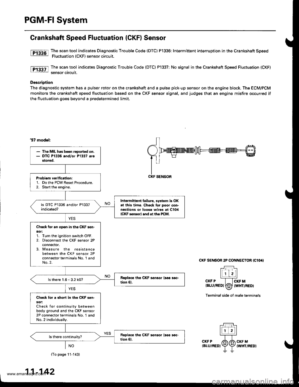
Grankshaft Speed Fluctuation (CKF) Sensor
fF13361l Tj":""l.tool indicates Diagnostic Trouble Code (DTCI P1336: Intermittent interruption inthe Crankshaft Speed: Fluctuation (CKF) sensor circuit.
The scan tool indicates Diagnostic Trouble Code (DTC) P1337: No signal in the Crankshaft Speed Fluctuation (CKF)
sensor circuit.
Description
The diagnostic system has a pulser rotor on the crankshaft and a pulse pick-up sensor on the engine block. The ECM/PCM
monitors the crankshaft speed fluctuation based on the CKF sensor signal, and judges that an engine misfire occurred if
the fluctuation goes beyond a predetermined limit.
37 mod.l:
CKF SENSOR 2P CONNECTOR IClO4I
T:]l-r'r Lll
l1 zLl''''CKF P I lcKF Mtalu/aeot fdJ twxrneor\-7
Terminal side of male terminals
(To page 11-113)
11-142
- Tho MIL ha3 been reported on.- DTC P1336 and/or P1337 arestored.
Problem verificrtion:1. Do the PCM Reset Procedure.2. Start the engine.
Intermittent {ailure, systom is OK.l thia timo. Ch6ck tor poor con-nections or loose wir$ at ClorlICKF sonsorl .nd at tho PCM.
Chock tor an opon in th6 CKF .en'30r:1. Turn the ignition switch OFF.2. Disconnect the CKF sensor 2Pconnector,3, M easure the resistancebetween the CKF sensor 2Pconnector terminals No. 'l andNo.2.
ls there 1.6-3.2 kO?
Check fo. a short in the CKF 3en-sot:Check for continuity betweenbody ground and the CKF sensor2P connector terminals No. 1 andNo.2 individually.
CKF SENSOR
www.emanualpro.com
Page 346 of 1395
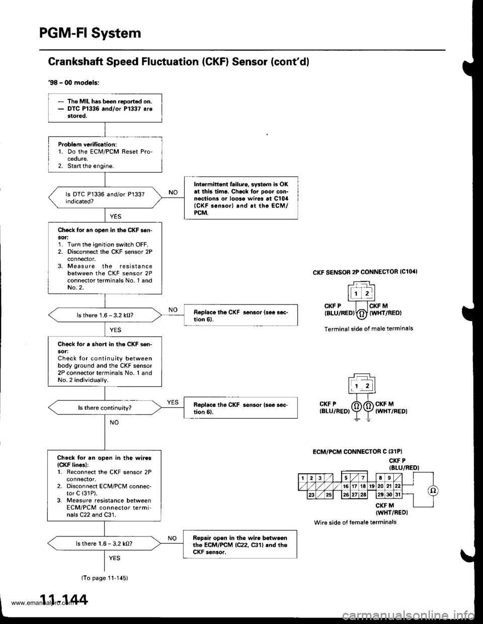
PGM-FI System
Grankshaft Speed Fluetuation (CKFI Sensor (cont'dl
.98 - 00 modols:
CKF SENSOR 2P CONNECTOR IClO'I
r-:-i-_ltr_- |l1 2ll,,-'CKF P I ICKF MtsLuneotTOl wlrrneo)\7
Terminal side of male terminals
r:l
t! El
.KFP XA"*."talu rneor \:f
f rwxvneor
ECM/PCM CONNECTOR C (31P)
CKF PIBLU/REDI
CKF M(WHT/BEOI
Wi16 side of l6male terminals
1278__l
-lI(o
T
161716't9202122
,/ 2s262728293()3l
M
- The MIL has boon reported on.- DTC P1336 and/or P1337 arestored.
ProblGm verification:1. Do the ECM/PCM Reset Pro-cedure,2. Stan the engine.
Inte.mittant failuro, 3y*om b OKat thb tima. Chack lor ooor con-nections or looso wirea at C10a{CKF sensorl and.t the ECM/PCM,
Chgck forun open in tho CKF son-sori1. Turn the ignition switch OFF.2. Disconnect the CKF sensor 2Pconnector.3. Measure the resistancebetween the CKF sensor 2Pconnector terminals No. 1 andNo.2.
lsthere 1.6 - 3.2 kO?
Check for a short in the CKF sen-
Check lor continuity betweenbody ground and the CKF sensor2P connector terminals No. 1 andNo.2 individually.
Check for an open in the wiresICKF linca):1. Feconnect the CKF sensor 2Pconnector.2. Disconnect ECM/PCM connec-tor C (31P).
3. Measure resistance betweenECM/PCM connector termi'nals C22 and C31.
Repair opon in the wir6 botwoonthe ECM/PCM 1C22, glll lnd th6CKF s6n3or.
ls there 1.6 - 3.2 kO?
(To page 11'1451
11-144
www.emanualpro.com
Page 348 of 1395
PGM-FI System
Crankshaft Position/Top Dead Center/Cylinder Position (CKP/TDC/CYP) Sensor
The scan tool indicates Diagnostic Trouble Code (DTC)
Center/Cvlinder Position tCKP/TDC/CYP) sensor circuit.
P1359:A problem in the Crankshaft Position/Top Dead
- The MIL has been reoorted on.- DTC P1359 is stored.
Problem verific.tion:1. Do the ECM/PCM Reset Proce-dure.2. Start the engine. lf the enginewon't start, crank it continu-ouslyfor at least 15 seconds.
Intermitteni lailure, system is OK.Check for ooor connections orloos€ wires al C121 {distributor}and at the ECM/PCM.
ls DTC P1359 indicated?
Check for poor connections orloose wires between the distribu'tor and the EcM/PcM.
Substitute a known-good ECM/PCM, and recheck. ll symplom/indication goes away, replace theoriginal ECM/PCM.
11-146
www.emanualpro.com