1998 HONDA CR-V parts
[x] Cancel search: partsPage 489 of 1395

Transfer Assembly
Transfer Shaft Disassembly/
Reassembly
1. Support the transfer driven gear on steel blocks,
then press the transfer shaft out of damper hub,
Align the damper hub grooves and transfer drivengear teeth, and reassemble the damper hub. needle
bearing, and transfer driven gear.
Install the transfer shaft using a press.
13-50
us Ing
Transfer Gover A Bearing Outer
Race Replacement
NOTE: Coat all parts with MTF during reassembly.
1. Bemove the tapered roller bearing outer race from
transfer cover A by heating the cover to almost212"F (100oC) using a heat gun. Do not heat thecover over 212"F (100'C),
2. Install the 68 mm thrust shim in transfer cover A.
TRANSFER COVER A
ATTACXMCNT,52x68mft07746 - tD,t0500
Install the tapered roller bearing outer race
the special tools and a press.
BEARING OUTER RACE
BEARING OUTER RACE
www.emanualpro.com
Page 490 of 1395

Transfer Housing Bearing Outer Race Replacement
NOTE: Coat all parts with MTF during reassembly.
1. Remove the tapered roller bearing outer race from
the transfer housing.
TBANSFER HOUSING
Install the new tapered roller bearing outer race
using the special tools and a press
DRIVER07749 - 0o1(xD0
TRANSFER HOUSINGBEARING OUTERRACE
J
i=
\l
DRIVER ATTACHMENT
13-51
Bealing Outer Race Locations
and Special Tool APP|ications
TRANSFER HOUSINGSectionalViewATTACHMENT,62x68mm07746 - 0010500
ATTACHMENT,62x68mm07?a6 - 0010500
ATTACHMENT,52x55mm07715 - 0010400
www.emanualpro.com
Page 491 of 1395
Transfer Assembly
Reassembly
Note these items during reassembly:. While reassembling the transfer assembly:- Check and adjust the transfer gear tooth contact.- Measure and adjust the transfer gear backlash.- Check and adjust the tapered roller bearing start-Ing rorque.
. Coat all parts with MTF during reassembly.. Replace the tapered roller bearing and the bearingouter race as a set if either part is replaced.. Replace the transfer drive gear and the transfer dri-ven gear shaft as a set if either part is replaced,
Outline of Assembly
1.Select the 35 mm thrust shim.
Perform this procedure if the transler driven gear
shaft or the tapered roller bearing on the transferdriven gear shaft is replaced.
Preassemble the parts to check and adjust transfergear backlash and transfer gear tooth contact.
Disassemble the parts, then assemble the transferdriven gear shaft and its related parts.
4. Measure and adjust the staning torque of the trans-fer driven gear shaft tapered roller bearing.
5. Assemble the transfer shaft and jts related parts.
6. Measure and adjust the total starting torque.
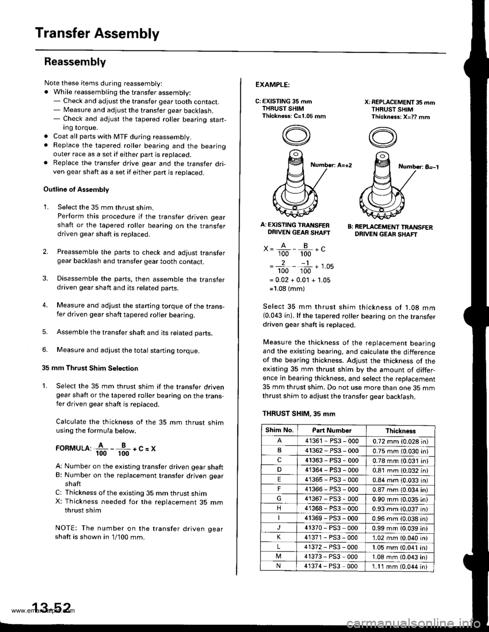
35 mm Thrust Shim Seleqtion
1. Select the 35 mm thrust shim if the transfer drivengear shaft or the tapered roller bearing on the trans-fer driven gear shaft is replaced.
Calculate the thickness of the 35 mm thrust shimusing the formula below.
ronrvruu:fi--fr-+c=x
A: Number on the existing transfer driven gear shaftB: Number on the replacement transfer driven gear
shaft
C: Thickness ofthe existing 35 mm thrust shimX: Thickness needed for the replacement 35 mmthrust shim
NOTE: The number on the transfer driven gear
shaft is shown in 1/100 mm.
2.
3.
13-52
EXAMPLE:
C: EXISTING 35 mmTHRUST SHIMThicknoss: C=1.05 mm
X: REPLACEMET{T35 mmTHRUST SHIMThickness: X=?? mm
Number: A=+2Number: B-l
A: EXISTING TRANSFERDRIVEN GEAR SHAFT
x= A - B -.'- 100 100 -
2-1
100 100 '-
= 0.02 + 0.01 + 1.05-'1.08 (mm)
B: REPLACEMENT TRANSFERDRIVEN GEAF SHAFT
Select 35 mm thrust shim thickness ot '1.08 mm(0.043 in). lf the tapered roller bearing on the transferdriven gear shaft is replaced.
Measure the thickness of the replacement bearingand the existing bearing, and calculate the differenceof the bearing thickness. Adjust the thickness of theexisting 35 mm thrust shim by the amount of differ-ence in bearing thickness. and select the replacement
35 mm thrust shim. Do not use more than one 35 mmthrust shim to adjust the transfer gear backlash,
THRUST SHIM. 35 mm
Shim No.Part NumberThickness
41361 - PS3 - 0000.72 mm (0.028 in)
B41362-PS3-0000.75 mm (0.030 in)
c41363-PS3-0000.78 mm (0.031 in)
41364-PS3-0000.81 mm (0.032 in)
E41365-PS3-0000.84 mm (0.033 in)
F4r366-PS3-0000.87 mm (0.034 in)
41367-PS3-0000.90 mm (0.035 in)
n41368-PS3-0000.93 mm (0.037 in)
41369-PS3-0000.96 mm {0.038 in)
41370-PS3-0000.99 mm (0.039 in)
41371 - PS3 - 0001.02 mm (0.040 in)
L41372-PS3-0001.05 mm (0.041 in)
41373-PS3-0001.08 mm (0.043 in)
N41374-PS3-0001.11 mm (0.044 in)
www.emanualpro.com
Page 496 of 1395
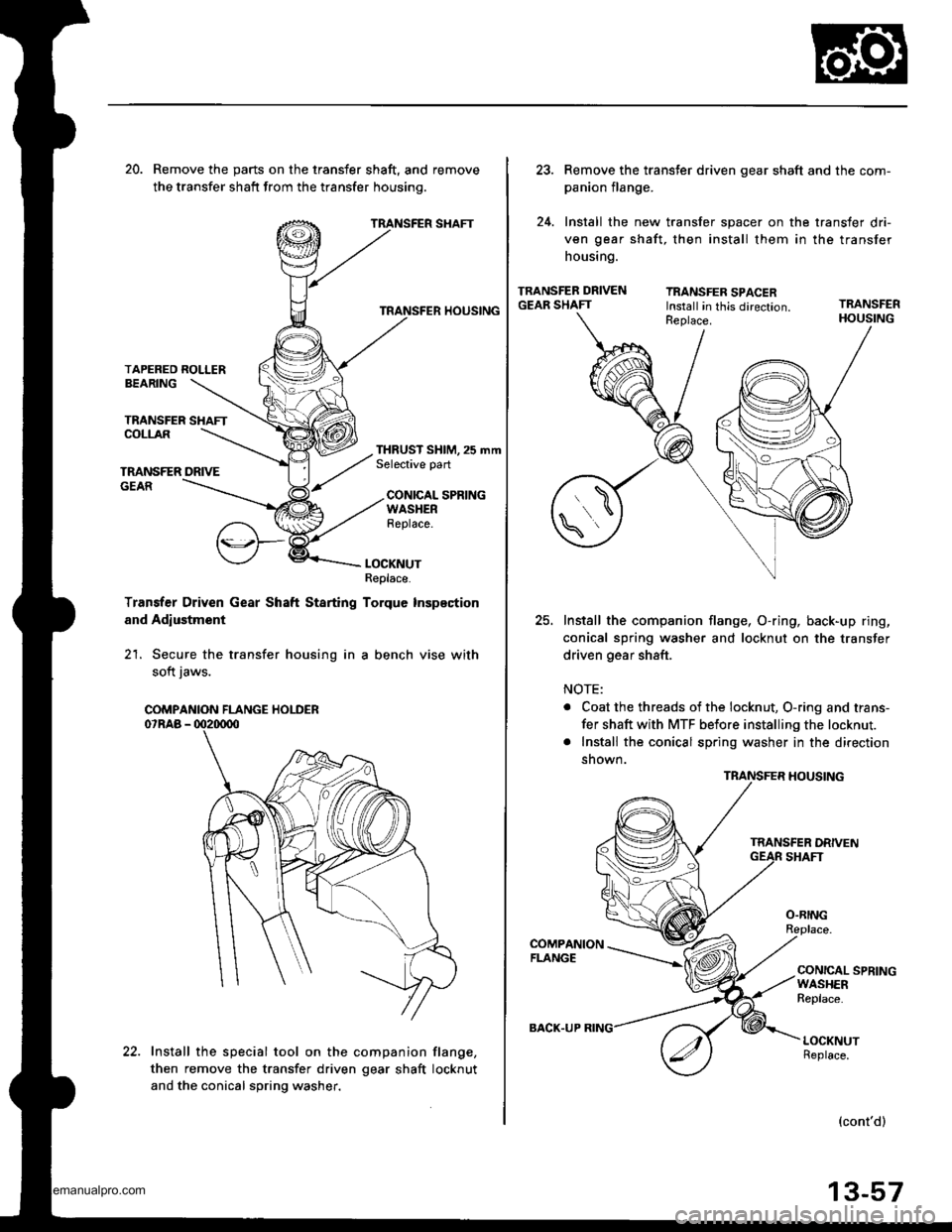
20. Remove the parts on the transfer shaft, and remove
the transfer shatt from the transfer housinq.
TRANSFER SHAFT
TRANSFER HOUSING
TAPERED ROLLERBEARING
TRANSFER SHAFTCOLLAR
TMNSFER DRIVEGEAR
THRUST SHIM, 25 mmSelective part
CONICAL SPRINGWASHERReplace.
LOCKNUTReplace.
Transter Driven Gear Shaft Starting Torque Inspection
and Adlustment
21. Secure the transfer housing in a bench vise with
soft iaws.
Install the special tool on the companion flang€,
then remove the transfer driven gear shaft locknut
and the conical spring washer.
COMPANION FLANGE HOLDER
22.
BACK.UP
Remove the transter driven gear shaft and the com-
panion flange.
Install the new transfer spacer on the transfer dri-
ven gear shaft, then install them in the transfer
housing.
TRANSFER DRIVENGEAR SHAFTTRANSFER SPACERInstall in this direction.TRANSFER
25.Install the companion flange, O-ring, back-up ring,
conical spring washer and locknut on the transfer
driven gear shaft.
NOTE:
. Coat the threads of the locknut, O-ring and trans-
fer shaft with MTF before installing the locknut.
. Install the conical spring washer in the direction
shown.
TRANSFER HOUSING
O.RING
COMPANIONFLANGECONICAL SPRINGWASHERReplace.
LOCKNUTReplace.
(cont'd)
13-57
www.emanualpro.com
Page 497 of 1395

Transfer Assembly
Reassembly (cont'dl
26. Secure the transfer housing in a bench vise with
soft jaws.
COMPANION FLANGE HOLDER07RAB - 002tD00
27. Install the special tool on the companion flange.
then tighten the transfer driven gear shaft locknut
while measuring the starting torque of the transfer
driven gear shaft.
STARTING TOROUE:
0.98 - 1.39 N.m
{10.0 - 1i1.2 kgf.cm, 8.68 - 12.3 lbf in}
TIGHTENING TOROUE:
132 - 216 N.m
(13.5 - 22.0 kgf.m, 97.6 - 159 lbf.ft)
NOTE:
. Rotate the companion flange several times to
seat the tapered roller bearing, then measure the
startrng torque.
. lf the starting torque exceeds 1.39 N.m (14.2
kgf.cm, 12.3 lbf.in), .eplace the transfer spacer
and reassemble the parts. Do not adjust the
torque with the locknut loose.
. lf the tightening torque exceeds 216 N.m (22.0
kgf.m, 159 lbf'ft), replace the transfer spacer and
reassemble the parts.
. Write down the measurement of the starting
torque: it is used to measure the total starting
torque.
28. Stake the locknut into the transfer driven oear shaft
using a 3.5 mm punch.
0.7 - 1.2 mm(0.03 - 0.05 inl
Point to bestaked.
Install the transfer shaft assemblv in the transfer
housing, then install the tapered roller bearing,
transfer shaft collar, 25 mm thrust shim, transfer
drive gear, conical spring washer, and transfer shaft
locknut on the transfer shaft.
NOTE:
. Coat the threads of the locknut and transfer shaft
with MTF before installing the locknut.
. lnstall the conical spring washer in the direction
snown.
TMNSFER SHAFTASSEMBLY
TRANSFER HOUSING
TAPERED ROLLERBEARING
TRANSFER SHAFTCOLLAR
TRANSFER DRIVEGEAR
PUNCH3.0-3.5 mm10.12 - 0.1a inl
THRUST SHIM, 25 mmSelective part
CONICAL SPRINGWASHEBReplace.
LOCKNUTReplace.
29.
www.emanualpro.com
Page 516 of 1395

Gearshift Mechanism
Overhaul
Note these itemsl
. InsDect rubber parts for wear and damage when disassembling'
. Check that the new cotter pin is seated firmly.
. Be carelul not to damage the guide pipe when removing the cables'
CHANGE LEVER KNOS8 N.m (0.8 kgl.m, 5.8 lbf.ft)
SELECT CABLE
PLATESReplace.WASHEB
I curur(PlN I I
\II
\"1 a,?-@ -.4'
-(
I
\
6x9.8
Guide pipe in theDOOI,
COTTEF PIN
PLASTIC WASHERGUIDE PIPESSHIFT CABLE
'l.0 mmN.m {1.0 kgf.m, 7.2 lbf.ftl
(stLlcoNE
GREASEI
LEVER ASSEMBLY
8 x 1.25 mm13 N.m 11.3 kgt'm,9.4lbf ft)
FLOATINGCOLLAR
13-77
www.emanualpro.com
Page 519 of 1395
Description
General Operation
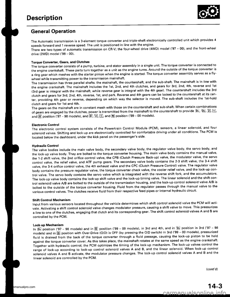
The Automatic transmission is a 3-element torque converter and triple-shaft electronically controlled unit which provides 4
speeds forward and 1 reverse speed The unit is positioned in line with the engine'
There are two tvoes of automatic transmission on CR-V; the four-wheel drive (4WD) model ('97 - 00)' and the front-wheel
drive (2WD) model ('98 - 00).
Toroue Converter, G€ars, and Clutches
The torque converter consists of a pump. turbine. and stator assembly in a single unit. The torque converter is connected to
the engine crankshatt. These parts turn together as a unit as the engine turns. Around the outside of the torque converter is
a ring gear which meshes with the starter pinion when the engine is started. The torque converter assembly serves as a fly-
wheel while transmitting power to the transmission mainshaft.
The transmission has three parallel shafts: the mainshaft. the countershaft, and the sub-shaft. The mainshaft is in line with
the engine crankshaft. The mainshaft includes the 1st, 2nd. and 4th clutches, and gears lor 3rd,2nd,4th. reverse and 1st
(3rd gear is integral with the mainshaft, while reverse gear is integral with the 4th gear). The countershaft includes the 3rd
clutch and gears for 3rd,2nd, 4th, reverse, 1st, and park. Reverse and 4th gears can be locked to the countershaft at its cen-
ter, providing 4th gear or reverse, depending on which way the selector is moved. The sub-shaft includes the lst-hold
clutch and gears for lst and 4th.
The gears on the mainshaft are in constant mesh with those on the countershaft and sub-shaft. When certain combinations
of gears are engaged by the ctutches, power is transmitted from the mainshaft to the countershaft to provide E, D!, tr, tr,
and E position ('97 - 98 models). and E. E, E, and E position ('99 - 00 models)'
Electlonic Control
The electronic controt system consists of the Powenrain Control Module (PCM), sensors, a linear solenoid, and four
solenoid valves. Shifting and lock-up are electronically controlled for comfortable driving under all conditions. The PCM is
located below the dashboard, under the kick panel on the passenger's side.
Hydraulic Control
The valve bodies include the main valve body, the secondary valve body, the regulator valve body, the servo body, and
the lock up valve body. They are bolted to the torque converter housing. The main valve body contains the manual valve,
the 1-2 shift valve, the 2nd orifice control valve. the CPB {Clutch Pressure Back-up) valve, the modulator valve, the servo
control valve. the relief valve, and ATF pump gears. The secondary valve body contains the 2-3 shift valve, the 3-4 shift
valve, the 3,4 orifice control valve. the 4th exhaust valve and the CPC (Clutch Pressure Control) valve. The regulator valve
bodv contains the pressure regulator valve, the torque converter check valve, the cooler relief valve, and the lock-up con-
trol valve. The servo body contains the servo valve which is integrated with the reverse shift tork, and the accumulators
The lock-up valve body contains the lock-up shift valve and the lock-up timing valve. The linear solenoid and the shift con-
trol solenoid valve Ay'B are bolted to the outside of the transmission housing, and the lock-up control solenoid valve Ay'B is
bolted to the outside of the torque converter housing. Fluid trom the regulator passes through the manual valve to the
various control valves. The clutches receive fluid from their respective feed pipes or internal hydraulic circuit
ShiftControl Mechanism
input from various sensors located throughout the vehicle determines which shift control solenoid valve the PCM will acti-
vate. Activating a shift control solenoid valve changes modulator pressure, causing a shift valve to move. This pressurizes
a line to one of the clutches. engaging that clutch and its corresponding gear. The shift control solenoid valves A and B are
controlled by the PCM.
Lock-up Mechanism
tn E! position (,97 - 98 modets) and in E position ('99 - O0 models), in 3rd and 4th, and in Del position in 3rd ('97 - 98
models) and in El position with Over,Drive (O/D) is OFF (by pressing rhe O/D switchl in 3rd ('99 - 00 models), pressurized
fluid is drained from the back of the torque converter through a fluid passage, causing the lock-up piston to be held
against the torque converter cover, As this takes place, the mainshaft rotates at the same speed as the engine crankshaft.
Together with hydraulic control, the PcM optimizes the timing of the lock-up mechanism The lock-up valves control the
range of lock-up according to lock-up control solenoid valves A and B, and the linear solenoid. When lock-up control
solenoid valves A and B activate, the modulator pressure changes. The lock-up control solenoid valves A and B and the
linear solenoid are controlled by the PCM.
{cont'd)
14-3
www.emanualpro.com
Page 524 of 1395
Description
Power Flow (cont'dl
E Position
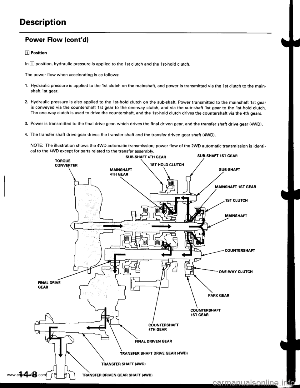
In E position, hydraulic pressure is applied to the lst clutch and the lst-hold clutch.
The power flow when accelerating is as follows:
1. Hydraulic pressure is applied to the lst clutch on the mainshaft, and power is transmitted via the 1st clutch to the main-
shaft 1st gear.
Hydraulic pressure is also applied to the lst-hold clutch on the sub-shaft. Power transmitted to the mainshaft 1st gear
is conveyed via the countershaft 1st gear to the one-way clutch, and via the sub-shaft 1st gear to the 1st-hold clutch.The one-way clutch is used to drive the countershaft, and the 1st-hold clutch drives the countershaft via the 4th gears.
Power is transmitted to the final drive gear, which drives the final driven gear, and the transfer shaft drive gear (4WD),
The transfer shaft drive gear drives the transfer shaft and the transfer driven gear shaft (4WD).
NOTE; The illustration shows the 4WD automatic transmissjon; power flow ot the 2WD automatic transmission is identi-cal to the 4WD except for parts related to the transfer assembly.
SUB.SHAFT 4TH GEARSU8-SHAFT 1ST GEAR
4.
TOROUECONVERTERlST.HOLD CLUTCHSUB.SHAFT
1ST GEAR
lST CLUTCH
COUNTERSHAFT
ONE.WAY CLUTCH
FINAL DRIVEGEAR
PARK GEAB
COUNTERSHAFT4TH GEAR
FINAL DRIVEN GEAR
TRANSFER SHAFT ORIVE GEAR {4WD}
TRANSFER SHAFT {4WD}
14-8TRANSFER DRIVEN GEAR SHAFT {4WD)
www.emanualpro.com