Page 983 of 1395
Doors
Component Location Index
Front Door:
NOTE: Refertothe 1997 Series Honda CR-V Body Repair Manual (P/N 61S1030) forfrontdoor removat.
ffi
*Y
lPOWER DOOR LOCKCONTROL UNIT
t\q
efl-Nr2
/ *-8
ARMREST
OOOR CHANNEL TAPE
INNERW€ATHERSTRIP
v
MIRROR MOUNTCOVER
----s-re
"\-,-.*
€fl
FRONT DOORPosition Adjustment,page 20-22
FRONT DOOR PANELRemoval and lnstallation, page 20,7
OUTER MOLDING
PLASTICCOVER
,.r=R
\//
::r
HINGE
20-2
www.emanualpro.com
Page 1003 of 1395
Doors
Front and Rear Door Glass
Adiustment (cont'dl
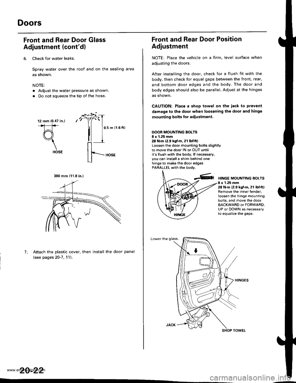
6. Check for water leaks.
Spray water over the roof and on the sealing area
as snown.
NOTE:
. Adjust the water pressure as shown.
. Do not soueeze the tio of the hose.
12 mm {0.47 in.l
#
(r\"1
HOSE
-"'*r"i
,'r)"f
tl
0.5 m (1.6 ftl
7. Attach the plastic cover, then install the door panel
(see pages 20-7, 'l 1),
20-22
..-
300 mm 111.8 in.)
Front and Rear Door Position
Adjustment
NOTE: Place the vehicle on a firm, level surface when
adiusting the doors.
After instailing the door, check for a flush fit with the
body, then check lor equal gaps between the front, rear.
and bottom door edges and the body. The door and
body edges should also be parallel. Adjust at the hinges
as shown.
CAUTION: Placa a shop towel on the iack to prevent
damage to the door when loosening the door and hinge
mounting bolts lor adiustment.
DOOR MOUNTING BOLTSI x 1.25 mm28 N.m 12.9 kgtr.m, 21 lbI.ftlLoosen the door mounting bolrs slighrlyto movethe door lN or OUT untilit's flush with the bodv. lf necessary,you can installa shim behind onehinge to make the door edgesPARALLEL with the bodv.
HINGE MOUNTING BOLTS8 x 1.25 mm28 N,m 12.9 kgt.m. 21 lbl.ftlRemove the inner fender,loosen the hinge mountingbolts, and move the doorBACKWARD or FORWARD,UP or DOWN as necessaryto equalize the gaps.
Lower the glass.
www.emanualpro.com
Page 1058 of 1395
Front Grille
Replacement
CAUTION: When prying with a flat-tip screwdriver,
wrap it with protective tape, and apply protective tape
around the related parts to prevent damage.
NOTE: Take care not to scratch the front orille and front
oumper.
1. Remove the front grille emblem cover. Loosen and
remove the grille mounting screws. and remove the
front grille by pulling it forward.
>: Screw locationsa>,5s>,2
@-l @,"l
NOTE: Insert a Phillips screwdriver through theholes in the front grille, then loosen the screws.
2. Installation is the reverse of the removal procedure.
20-77
www.emanualpro.com
Page 1088 of 1395
Frame Repair Chart
(cont'd)
Side view:
Unit: mm (in.)
0: Inner diamete.
POINT d3
o15 {0.591 For Trensmission Mount
d15 10.591 For Trrnsmi3donMount
POINT d1
t13 10.5'll For Transmb3ionMount
POINT el
613 10.51) For TransmirsionMouni
z
t13 {0,511 For Engin6 Mount
M10 x Pl.25
t13 10.51) For Uppcr Arm
.25
POINT,1710.67)Fof Re.r Beam
o12 (0.,171 For Right Front Stop
POINT c1
o16 10.631 Locate Hole
612 {0.47} For Left Front Stoo
b2
r12 {0.47) For Left Front StoD
t5011.97| Locrt. Hol.
POINT
t17 10.671 Fo. R..r
r'17 10.671 For Rcar Bo.mt12 {0.47} For Right Front Stop
POINT c2
130POINT h1
DamperLower BushingPoint
o11 (0.{31 For Engine Mount
20-108
www.emanualpro.com
Page 1145 of 1395
A/C System Torque Specifications
EVAPORATOR
SUCTION LINE
SUCTION HOSE
RECEIVER LINE ARECEIVEN LINE B
RECEIVER/ORYER
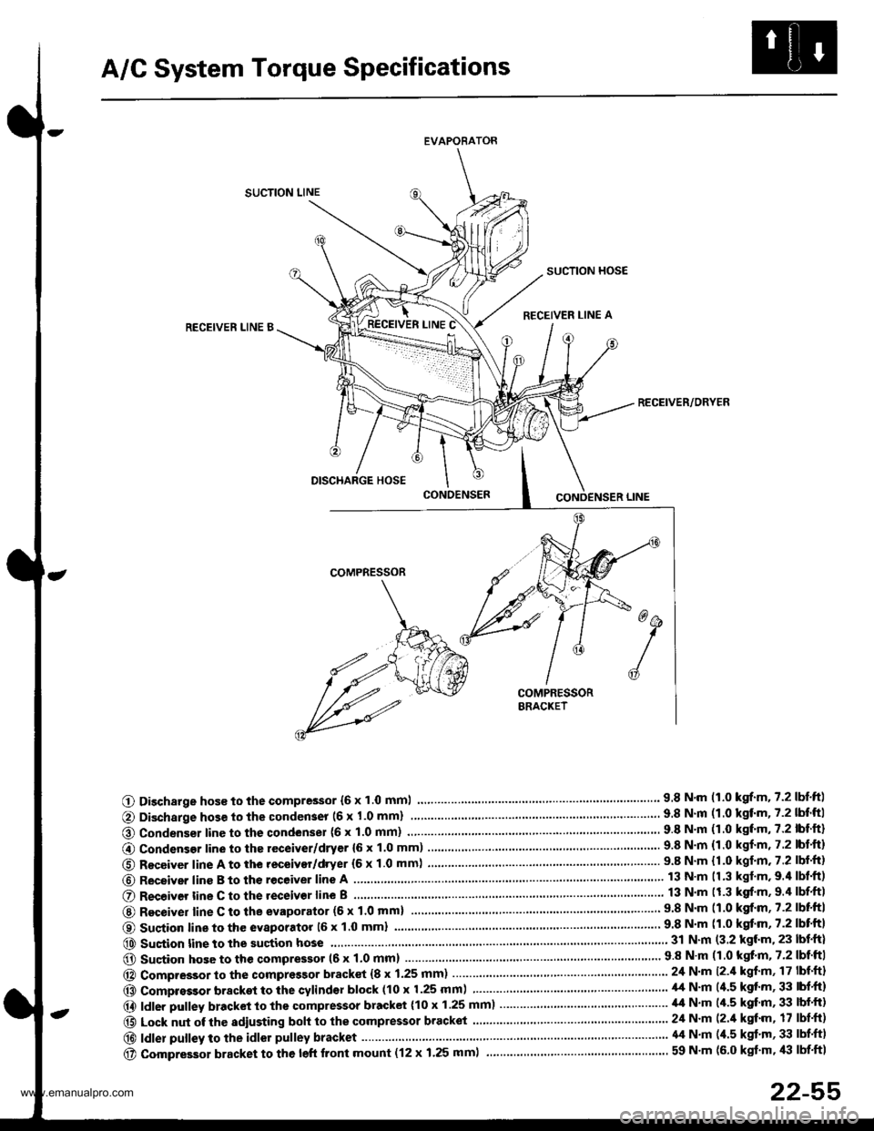
O Discharge hos€ to the compressor {6 x 1.0 mml.... 9.8 N.m 11.0 kgrf.m.7.2lbtftl
@ Condenser line to the condenser (6 x 1.0 mm)
@ Condensor line to the receiver/dryer {6 x 1.0 mm) ........9.8 N.m {1.0 kgf.m, 7.2 lbt.ft)
O Receiver line A to the receivor/dryer (6 x 1.0 mm) ...... ....................... 9.8 N.m {1.0 kgf.m.7.2 lbf.ft}
@ Receiver line B to th€ receive. line A
O R€ceiver tine C to the receivor line B
@ Recoiver line C to the evaporator (6 x 1'0 mml9.8 N'm (1.0 kgf.m,7.2lbtftl
O Sustion line to the evaporatot 16 x 1.0 mml
@ Sustion line to the suction hose...... 31 N.m (3.2 kgl.m, 23 lbf.ft)
@ Sucion hose to the qompressor (6 x 1.0 mm) .....'...' 9 8 N'm (1 0 kgt'm, 7'2 lbf'ftI
@ Compressor to the compressor bracket {8 x 1.25 mm) ... 24 N.m l2.il kgf'm, 17 lbf'ft}
@ Compressor bracket to the cylindsr block (10 x 1.25 mm) ................ ......... il,t N'm (4.5 kgt'm, 33 lbf'ft)
@ ldler pulley bracket to the compressor bracket (10 x 1.25 mm)..................... ,14 N.m (/r.5 kgf'm, 33 lbf'ft)
@ Lock nut of the sdiusting boh to the compressor bracket ......................... 24 N'm (2./t kgt'm, 17 lbf'ft)
@|d|erpu||eytotheid|orpu||eybracket.....'..........................'....\
.'.....'........'....44N.m(4.5kg''m'33|bf.f)
@ compressor bracket to the left front mount (12 x 1.25 mml ................... ............................ 59 N'm (6.0 kgt'm, /l:| lbf'ft1
22-55
www.emanualpro.com
Page 1152 of 1395
Compressor
Replacement
lf the compressor is marginally operable. run the
engine at idie speed, and let the air conditioner
work for a few minutes. then shut the engine off.
Disconnect the negative cable from the battery.
Recover the refrigerant with a recovery/recycling/
charging station (see page 22-59).
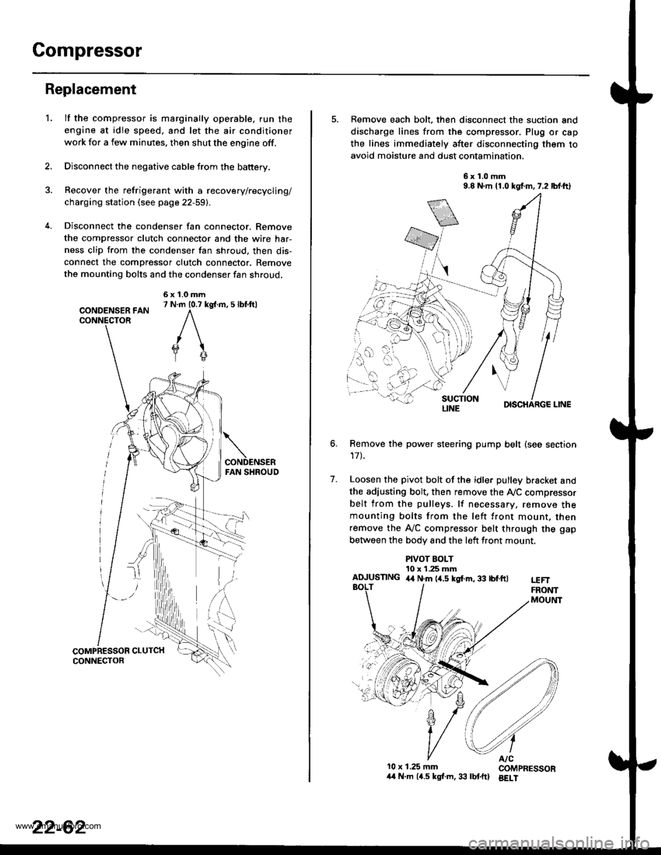
Disconnect the condenser fan connector. Remove
the compressor clutch connector and the wire har-
ness clip from the condenser fan shroud, then dis-
connect the compressor clutch connector. Remove
the mounting bolts and the condenser fan shroud,
CONDENSER FANCONNECTOR
6x1.0mm7 N.m 10.7 kg{.m, 5 lbl.ftl
'L
2.
5. Remove each bolt, then disconnect the suction and
discharge lines from the compressor. Plug or cap
the lines immediately after disconnecting them to
avoid moisture and dust contamination,
6x1.0mm9.8 N.m 11.0 kgf.m,7.2 lbf.ft)
DISCHARGE LINE
Remove the power steering pump belt (see section
17t.
Loosen the pivot bolt of the idler pulley bracket and
the adiusting bolt, then remove the Ay'C compressor
belt from the pulleys. lf necessary, remove themounting bolts from the left front mount, thenremove the A,/C compressor belt through the gap
between the bodv and the left front mount.
6.
7.
PIVOT BOLT10 x 1.25 mmAIUUSTING 4,t N.m (4.5 kgf.m, 33 tbf.ftlt€FTFRONTMOUltlT
10x 1.25 mm COMPRESSOR/t4 N.m (4.5 kgl.m,33 lbtftl BELI
LINE
www.emanualpro.com
Page 1153 of 1395
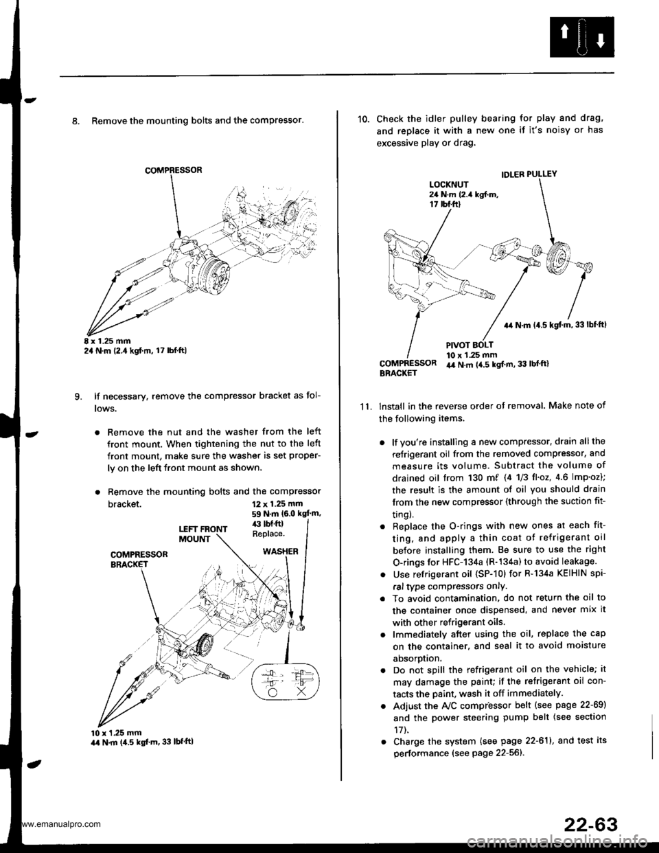
8. Remove the mounting bolts and the compressor.
E x 1.25 mm2a N.m (2.,1kgf.m, l7 lbl.ft)
lf necessary, remove the compressor bracket as fol-
lows.
. Remove the nut and the washer from the left
front mount. When tightening the nut to the left
front mount, make sure the washer is set proper-
ly on the left front mount as shown.
. Remove the mounting bolts and the compressor
bracket.
q
12 x 1.25 mm
59 N.m (6.0 kgt'm,
10 x 1,25 mmart N.m (4.5 kgf'm, 33 lbfftl
11.
10. Check the idler pulley bearing for play and drag,
and replace it with a new one if it's noisy or has
excessive play or drag.
lnstall in the reverse order of removal. Make note of
the following items,
. lf you're installing a new compressor, drain all the
reJrigerant oil from the removed compressor, and
measure its volume. Subtract the volume of
drained oil trom 130 m/ 14 U3 fl'o2,4.6 lmp'oz);
the result is the amount of oil you should drain
lrom the new compressor (through the suction fit-
trngl.
. Replace the O-rings with new ones at each fit-
ting, and apply a thin coat o{ refrigerant oil
before installing them. Be sure to use the right
O-rings for HFC-134a (R-134a) to avoid leakage.
. Use refrigerant oil (SP-10) for R-134a KEIHIN spi-
ral type compressors only.
. To avoid contamination, do not return the oil to
the container once dispensed, and never mix it
with other refrigerant oils.
. lmmediately after using the oil, replace the cap
on the container. and seal it to avoid moisture
aDsorprlon.
. Do not spill the refrigerant oil on the vehicle; it
may damage the paint; if the retrigerant oil con-
tacts the Daint, wash it off immediately.
. Adjust the Ay'C compr'essor b€lt (see psge 22-69)
and the power steering pump belt {see section
17t.
. Charge the system (see page 22-611, and test its
performance (see page 22-56]-.
IDLER PULLEY
+r N.m 14.5 kgt m,33lbf ftl
PIVOT BOLT10 x 1.25 mmir4 N.m {4.5 kgt m, 33 lbl'ft}BBACKET
www.emanualpro.com
Page 1160 of 1395
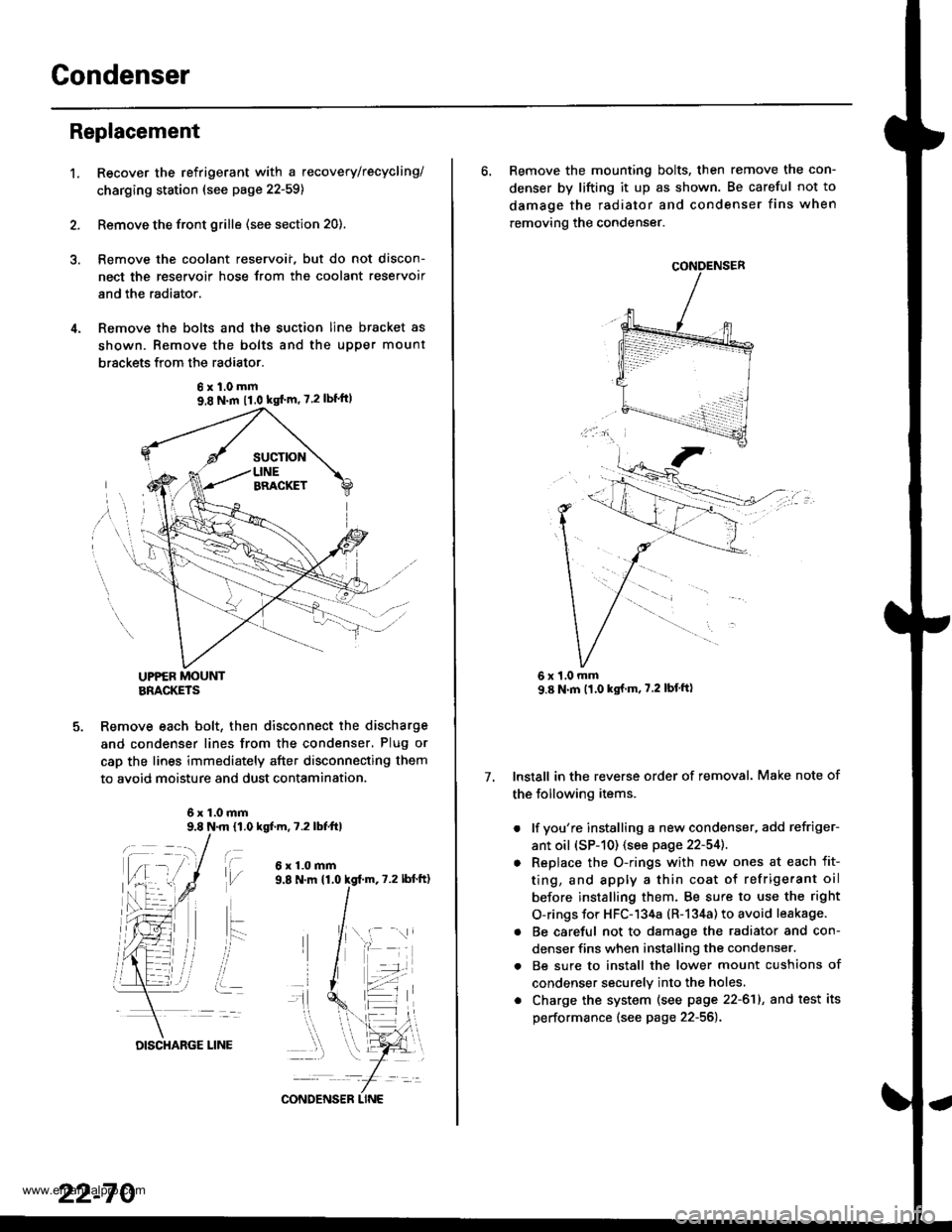
Gondenser
't.
Replacement
Recover the refrigerant with a recovery/recycling/
charging ststion (see page 22-59)
Remove the front grille (see section 20).
Remove the coolant reservoii, but do not discon-
nect the reservoir hose Jrom the coolant reservoir
and the radiator.
Remove the bolts and the suction line bracket as
shown. Remove the bolts and the upper mount
brsckets from the radiator.
UPPER MOUNTBRACKETS
Remove each bolt, then disconnect the discharge
and condenser lines from the condenser, Plug or
cap the lines immediately after disconnecting them
to avoid moisture and dust contamination.
6x1.0mm9.8 N.m 11,0 kgf.m, 7.2 lbfttl
t\,l/
ait- -:
i..
6x1.0mm
6xl.0mm9,8 N.m 11.0 kgf'm' 7.2lbf'ft)
22-70
DISCHARGE LINE
CONDENS€R LINE
6. Remove the mounting bolts, then remove the con-
denser by lifting it up as shown. Be careful not to
damage the radiator and condenser fins when
removing the condenser.
Install in the reverse order of removal. Make note of
the following items.
. lf you're installing a new condenser, add refriger-
ant oil (sP-10) (see page 22-54]..
o Replace the O-rings with new ones at each fit-
ting, and apply a thin coat of refrigerant oil
before installing them. Be sure to use the right
O-rings for HFC-134a (R-134a) to avoid leakage.
. Be careful not to damage the radiator and con-
denser fins when installing the condenser.
. Be sure to install the lower mount cushions of
condenser securely into the holes,
. Charge the system (see page 22-61), and test its
performance (see page 22-56).
7.
1,0 mm
www.emanualpro.com