Page 766 of 1395
Transmission
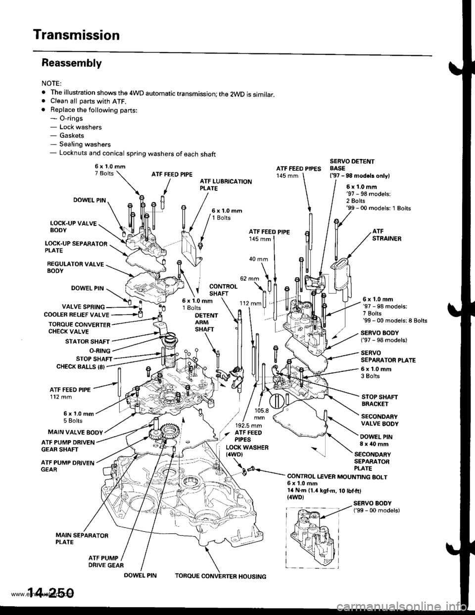
Reassembly
NOTE:
. The illustration shows the 4WD automatic transmission; the 2WD is similar.. Clean all parts with ATF.. Replace the following parts:- O-rings- Lock washers- Gaskets- Sealing washers- Locknuts and conical spring washers of each shaft
ATF FEED PIPE
/
ATF FEED PIPES145 mm
SERVO DETENTBASE(37 -98 modeb onlylATF LUBRICATIONPLATE6x1.0mm
2 Bolts'99 - 00 models: 1 Bolts
LOCK.UP VALVEBODY
LOCK.UP SEPARATORPLATE
REGULATOR VALVEBODY
DOWEL PIN
DOWEL PIN
VALVE SPRING
STATOR SHAFT
'-
'112mmll,
rlT
ATFSTRAINER
40 mm
j coNrRoLI SHAFT
COOLER BELIEF VALVE
TOROUE CONVERTERCHECK VALVE
6x1.0mm18olts
DETENTARMSHAFT
6x1,0mm'97 - 98 models:7 Bolts'99 - 00 models:8 Bolts
SERVO BODY('97 - 98 models)
SERVOSEPARATOR PLATE
6x1.0mm3 Bolts
STOP SHAFTBRACKET
SECONDARYVALVE BODY
OOWEL PIN8x40mm
O.RING
STOP SHAFTCHECK BALLS 18'
ATF FEED PIPE112 mm
6x1.0mm5 Eolts
ATF PUMP DRIVENGEAR SHAFT
ATF PUMP DRIVEN
MAIN SEPARATORPLATE
MAIN VALVE EOOY
SECONDARYSEPARATOR
d---.- PLATE--.- CONTROL I.EVER MOUNTING BOLT6x1.0ftm14 N.m (1.4 kgt.m, 10 tbf.ft)(4WD)SERVO BODY('99 - 00 models)
ATF PUMP
6x1.0mm
ATF FEEO PIPE
) / 105.8
/,,!.,::(./ afF FEEO,/ ptpEs
EP,---!ir{+*a r
fpffi4 i
x*hi
_ \zl
14-250
DRIVE GEAR
DOWEL PINTOBOUEHOUSING
www.emanualpro.com
Page 769 of 1395
17.
18.
19.
20.
21.
Install the sub-shaft assembly in the transmission
housing (see page 14-210 and 14-2'111.
lnstall the ATF magnet (4WD) in the transmission
housing, if necessary.
Install the reverse idler gear and gear shaft holder
(see page 14-231).
Install the differential assembly in the torque con-
verter housing.
Assemble the mainshaft and countershaft sub-
assembly (see page 14-206 and 14 207],, then install
them together in the torque converter houslng.
COUNTERSHAFTSUB-ASSEMBLY
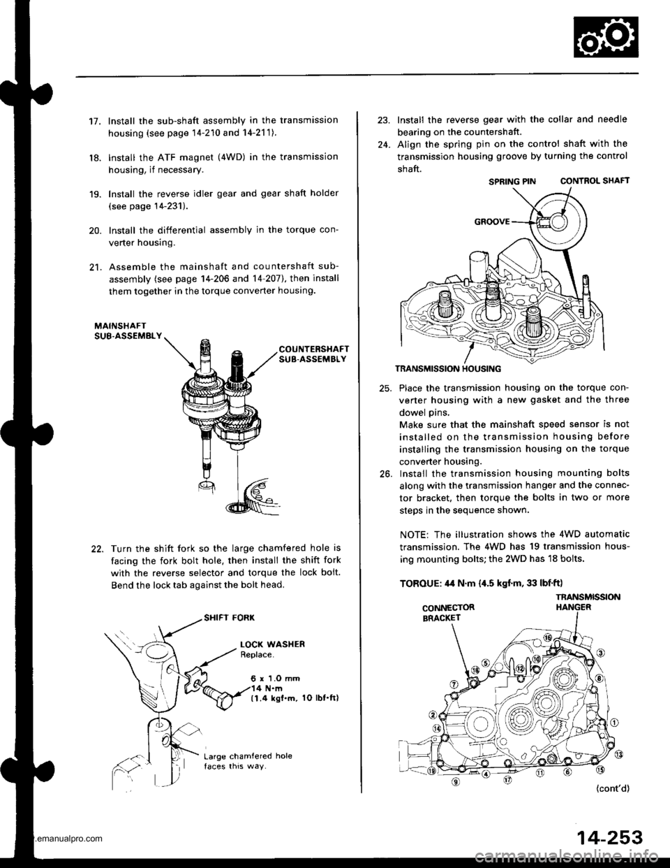
Turn the shift fork so the large chamfered hole is
facing the fork bolt hole. then install the shift fork
with the reverse selector and torque the lock bolt.
Bend the lock tab against the bolt head.
SHIFI FORK
LOCK WASHERBeplace.
6 r 'l.O mm4 N.m(1.4 ksl.m. 1O lbt.ft)
Large chamfered hole
24.
Install the reverse gear with the collar and needle
bearing on the countershatt.
Align the spring pin on the control shaft with the
transmission housing groove by turning the control
shaft.
SPRING PIN CONTROL SHAFT
TRANSMISSION HOUSING
25. Place the transmission housing on the torque con-
verter housing with a new gasket and the three
dowel pins,
Make sure that the mainshaft speed sensor is not
installed on the transmission housing before
installing the transmission housing on the torque
converter housing.
26. Install the transmission housing mounting bolts
along with the transmission hanger and the connec-
tor bracket, then torque the bolts in two or more
steos in the seouence shown.
NOTE: The illustration shows the 4WD automatic
transmission. The 4WD has 19 transmission hous-
ing mounting bolts; the 2WD has 18 bolts.
TOROUE: 44 N.m {,[.5 kgf.m, 33 lbf'ft)
{cont'd)
14-253
SPRING PIN
TNANSMISSION
www.emanualpro.com
Page 775 of 1395
Transmission
1.
lnstallation
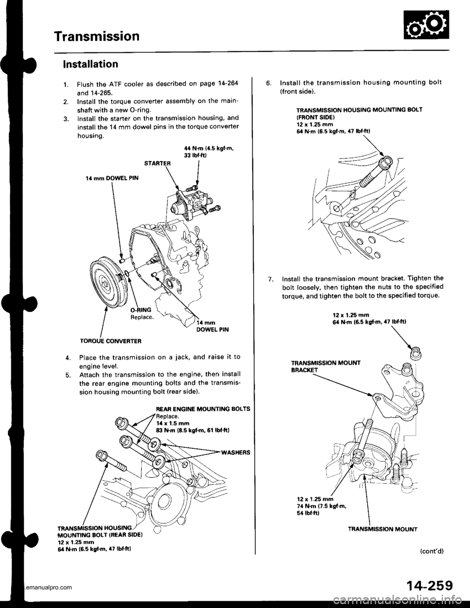
Flush the ATF cooler as described on page 14-264
and 14-265.
Install the torque converter assembly on the main-
shaft with a new O-ring.
lnstall the starter on the transmission housing, and
install the 14 mm dowel pins in the torque converter
housing.
44 N.m {{.5 kgf.m,33 rbf.f0
Place the transmission on a jack, and raise it to
engine level.
Anach the transmission to the engine, then install
the rear engine mounting bolts and the transmis-
sion housing mounting bolt (rear sidel.
14 mm DOWEL PIN
REAR ENGINE MOUNTING BOLTS
la x 1.5 mm8:l N.m (8.5 kgf.m, 61 lbf.ftl
MOUNTING BOLT {REAR SIDEI12 x 1.25 mm6il N.m 16.5 kgd.m, 47 tbt.ttl
6. Install the transmission housing mounting bolt
(front side).
TRANSMISSION HOUSING MOUNNNG BOLT
{FRONT SIDE)12 x 1.25 mm6,1 N m (6 5 kgl m, 47 lbf'ftl
Install the transmission mount bracket. Tighten the
bolt loosely, then tighten the nuts to the specified
torque, and tighten the bolt to the specified torque.
7.
12 x 1,25 mm6,a N.ft (6.5 kgtm,47rbf.ft)
t@
TRANSMISSION MOUNTBRACKET
12 x 1 .25 mm74 N.m (7.5 kgf.m,s{ tbtftl
(cont'd)
TBANSMISSION MOUNT
14-259
www.emanualpro.com
Page 776 of 1395
Transmission
Installation (cont'dl
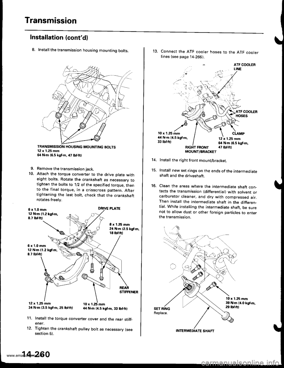
8. Install the transmission housing mounting bolts.
TRANSMISSION HOUSING MOUNTING BOLTS12 x 1.25 mm54 N.m 16,5 kgf.m, a7 lbtftl
9. Remove the transmission jack.
10. Attach the torque convener to the drive plate witheight bolts. Rotate the crankshaft as necessarv totighten the bolts to 'll2 of the specified torque, thento the final torque, in a crisscross pattern. Aftertightening the last bolt. check that the crankshaftrotates freelv.
6x1.0mln12 N.m (1.2 tgt m,8.t lbf.frl
6x1.0mm12 N.m {1.219{.m,8.7 tbtft,
12 x t.25 mm34 N.m 13.5 kgf.rn,25 lbf.ft)
8 x 1.25 mm2a N.m 12.5 kgf'm,18 tbt.ftl
DRIVE PLATE
STIFFENER
44 N.rn (4.5 kgt m, 33 lbtftl
11.
12.
Install the torque convener cover and the rear stiff_ener.
Tighten the crankshaft pulley bolt as necessary (seesection 5).
14-260
13. Connect the ATF cooler hoses to the ATF coolerlines (see page 14-266).
. ATF COOLERLINE
'i 'l'r',:,.) -
10 x 1.25 mm44 N.m (4.5 kgf.m,33 tbtftl
CLAMP
12 x 1.25 mm64 N.m 16.5 kg{.m,a7 tbt.ftlFRotrtT
15.
16.
't 4.
SET RINGReplace.
MOUNT/ARACKET
Install the right front mounvbracket.
Install new set rings on the ends of the intermediateshaft and the driveshaft.
Clean the areas where the intermediate shaft con_tacts the transmission {differential) with solvent orcarburetor cleaner, and dry with compressed air.Then install the intermediate shaft in the differen_tial, While installing the intermediate shaft, be surenot to allow dust or other foreign panicles to enterthe transmission.
l0 x 1.25 mm39 N.m 14.0 kgt.n,29 tbf.ftl
INTERMEDIATE SHAFT
www.emanualpro.com
Page 806 of 1395
Rear Differential Assembly
Removal/lnstallation
l!!@ Make sure tifts are ptaced property lseesection 11.
1. Drain the differential flujd (see page 15-14).
2. Mark the propeller shaft and companion flange of
the rear differential assembly so they can be rein-
stalled in their original positions.
PROPELLER SHAFTCOMPA'{ION FLANGE
Remove the propeller shaft from the rear differential
assemory.
Remove the rear differential damper.
12 POtt'lT BOLI8 x 1.25 mm32 N.m 13.3 tgf.m. 2a lbtft,
Mark
12 x 1.25 mm
15-16
5,1 N.m 15,5 kgf.m, iO tbf.fO
5, Place a transmission jack under the rear differential
assembly, then remove the right mounting bracket B
and the left mounting bracket 8.
Remove the breather tube from the breather tubefitting.
BREATHER TUBE flTNNG
www.emanualpro.com
Page 877 of 1395
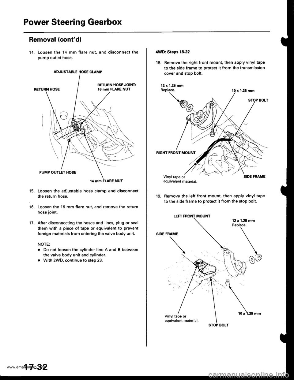
Power Steering Gearbox
AN'USTABLE HOSE CLAMP
Removal (cont'dl
14. Loosen the 14 mm flare
pump outlet hose.
nut, and disconnect the
14 mm FLARE NUT
15. Loosen the adjustable hose clamp and disconnect
the return hose,
16. Loosen the 16 mm flare nut, and remove the return
hose joint.
17. After disconnecting the hoses and lines, plug or seal
them with a piece of tape or equivalent to prevent
foreign maisrials from entering the valve body unit.
NOTE:
. Do not loosen the cylinder line A and B between
the valve body unit and cylinder.
. With 2WD, continue to step 23.
17 -32
STOP BOLT
10 x 1.25 mm
4WD: Stepr 18-22
18. Removethe right tront mount, then apply vinyl tape
to the side frame to protect it from the transmission
cover and stop bolt.
12 x 1.25 fiiAReplace.
RIGHT FRONT MOUNT
x 1,25 mm
SIDE FRAME
'19. Remove the left front mount, then apply vinyl tape
to the side frame to protect it from the stop bolt.
Vinyltape orequivalgnt material.
Vinyltap€ orequival€nt m6terial.
www.emanualpro.com
Page 1171 of 1395

Gonnector ldentification and Wire Harness Routing
How to ldentity Connectors:
ldentification numbers have been assigned to all connectors, The number is preceded by the letter "C" for connectors.
"G" for ground terminals or "T" for non-ground terminals.
Location
HarnessEngine CompartmsntDashboardOthers lFloor, Door,
8oof, Tailgate)
Starter cableT1, T2 and @
Battery ground cableG1 and O
Engine ground cableT3
Transmission ground cableT4
G3
Engine wire harnessC101 through C137
T101 and T102
G101
Engine compartment ware harnessC201 through C218
G201 and G202
Under-hood ABS fuse/relay box
wire harness
t5ano9
Main wire harnessC301 through C309
C351 through C361
C401 through C447
G401 and G402
Dashboard wire harnessC501 through C524 (C525)
G501
Left side wire harnessC551 through C581
G551, G552 and G553
Right side wire harnessC601 through C605
lnterior wire harnessC701 through C703
Rear bumper wire harnessC641 through C643
Heater sub-harnessC731 through C740
Secondary heated oxygen sensor
sub-harness
C721 through C722
Combination switch sub-harnessC751 through C760
Driver's door wire harnessC661 through C667
Front passenger's door wire harnessC6Tl through C676
Left rear door wire harnessC681 through C684
Right rear door wire harnessC69'l through C694
Rear wire harnessC611 through C520
Tailgate wire harnessC631 through C634
G631
SRS main harnessC801 through C808
G801
High mount brake light sub-harnessC651 through C653
Fuel tank oressure sensor sub-harnessC645 through C647
www.emanualpro.com