1998 HONDA CR-V Ignition
[x] Cancel search: IgnitionPage 274 of 1395
Troubleshooting
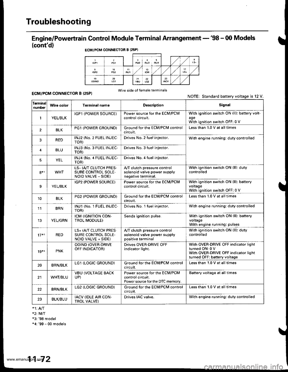
Engine/Powertrain Control Module Terminal Arrangement - '98 - 00 Models
(cont'd)
ECM/PCM CONNECTOR B {25PI
Wire side of female terminalsECM/PCM CONNECTOR B I25PI
*2t MlT*3: '98 model"4: '99 - 00 models
NOTE: Standard baftery voltage is l2
Ierminalnumb€tWire colorTerminsl nameDescriptionSignal
1YEUBLKIGPl (POWER SOURCE)Power source for the ECM/PClvlcontrol circuit.withagewith
ignition switch ON (ll): battery volt-
ignition switch OFF:0 V
BLKPG1 (POWER GROUND}Ground for the ECM/PClvl controlcircuit.Less than 1.0 V at all times
REDlNJ2 (No. 2 FUEL INJEC-roR)Drives No. 2 Iuel injector.With engine running: duty controlled
BLUlNJ3 1No. 3 FUEL INJEC-TOR)Drives No. 3Iuel jnjector.
YELlNJ4 {No.4 FUEL INJEC-TOR)Drives No. 4 fuel injector.
8*1WHTLS- (A"/T CLUTCH PRES.SURE CONTROL SOLE,NOID VALVE _ SIDE)
A,/T clutch pressure controlsolenoid valve power supplynegative terminal.
With ignition switch ON (ll): dutycontrolled
9YEUBLKIGP2 IPOWER SOURCE)Power source for the ECN,I/PCMcontrol circuit.With ignition switch ON (lll: bafteryvoltageWith ignition switch OFF:0 V
10BLKPG2 (POWER GROUND}Ground for the ECM/PCM controlcrrcurt.Less than '1.0 V at all times
' BRNlNJl (No. 1 FUEL INJECTOR)Drives No. l tuel injector.With engine running: duty controlled
YEUGRNrcM {rGNrTroN coN-TROL MODULE)Sends ignition pulse.With ignition switch ON (ll): batteryvoltageWith engine running: pulses
17*1REDLS+ (A,,IT CLUTCH PRESSURE CONTROL SOLE-NOID VALVE + SIDE)
A,/T clutch pressure controlsolenoid valve power supplypositive terminal
With ignition switch ON (ll): dutycontrolled
19*.PNK
ODIND (OVER-DRIVE
OFF INDICATOR}Drives OVER-DRIVE OFFindicator light.With OVER-DRIVE OFF indicator lightturned ON: 0 VWith OVER-DRIVE OFF indicator lightturned OFF: battery voltage
20BRN/BLKLG1 (LOGIC GROUND)Ground for the ECM/PCM controlcircuit.Less than 1.0 V at all times
WHT/BLUVBU (VOLTAGE BACKUP)Power source for the ECM/PCMcontrol circuit.Power source forthe DTC memory.
Battery voltage at all times
22BRN/BLKLG2 (LOGIC GROUND)Ground for the ECN4/PCM controlctrcutt,Less than 1.0 V at all times
23BLVBLUIACV {IDLE AIR CON.TROL VALVE)Drives IAC valve.With engine running: duty controlled
11-72
www.emanualpro.com
Page 275 of 1395
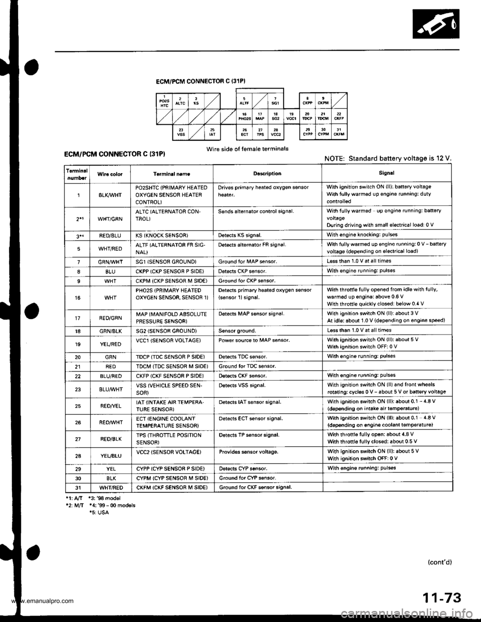
ECM/PCM CONNECTOF C (31PI
Wire side o{ female terminal€ECM/PCM CONNECTOR C (31P)NOTE: Standard battery voltage is 12 V.
TermidalD.3criptionSignal
8LI(WHTPOzSHTC {PRIII4ABY HEATEDOXYGEN SENSOR HEATERCONTROL)
Drivss prim6ry h$ted oxygsn sensorWilh ignition switch ON (ll): baneryvoltsgeWith ftrllywarmsd up €ngine runnang: duty
2"WHT/GBNALTC (ALTERNATOR CON,TROL)Sonds alternalor control signsl.With fully wafmod up €ngine rnningr ban€ryvoltagoDu ng driving with small elsctrical lo6d: 0 v
3'1FED/8LUKS (KNOCK SENSOR)Dstects KS signal.With engine knockang: pulses
5WHT/REDALTF (ALTERNATOR FR SIG-NAL}Detects alternator FR signal.Wth fullywarmed up €ngine running:0 V-batteryvoltag€ {d€pending on slsctrical load)
1GRN,4trHTSG1 (SENSOR 680UND}Ground for l/tAP sensor.L€ss than 1.0 v 6t all times
8BLUCKPP (CKP SENSOF P SIDE)Dat€cls CKP s6nsor.With €ngin€ runningr puls€s
9CKPI.,I| {CKP SENSOF M SIDE)Ground for CKP s€nsor.
15PHO2S {PRIMARY HEATEDOXYGEN SENSOR, SENSOR 1)Detocts pfimary he6t6d oxygen ssnsor
{sonsor 1)signal.with ihfottls fully opened from idle with fully,
walm6d up engins: above 0.6 VWith throttlo quickly clossd: below 0.4 v
17RED/GRNMAP (MANIFOLD ABSOLUTEPRESSURE SENSOR)
D6tects MAP s€nsor sign6l.With ignition switch ON (ll):about 3 VAt idls: aboul 1.0 V {dspsnding on engine speed)
18GRN/BLKSG2 (SENSOB GNOUNDiLsss than 1.0 V at all tim€s
19YEUBEDVCCl {SENSOR VOLTAGE)Power soufce to MAP s€nsor.With ignition switch ON (ll): about 5 VWith ignition switch OFF:0 V
20GRNTDCP {TDC SENSOR P SIDE)Derecis TDC sensor.With engine funning: Pulses
2lREDTDCM ITDC SENSOR M SID€)Ground for TDC sensor.
22BLU/REDCKFP (CKF SENSOR PSIDE)Dstscts CKF s€nsor.With sngins running: pulsss
23BLU/WHTVSS (VEHICLE SPEED SEN-soR)Dstscrs vss signal.With ignition switch ON (ll)and front wheelsrotaringrcyclss 0 v- 6bout 5 V or ban€ry voltage
25RED//ELIAT (INTAKE AIR TEMPERA'TURE SENSOB)Detacts IAT sensor signal.With igniiion switch ON (ll): about 0.1 - 4.8 V(d€p€nding on iniate air t€mp€raturc)
26REO/WHTECT {ENCINE COOLANTTEMPERATURE SENSOR)oetscts ECT sensor signal.With ignition switch ON (ll): about 0.1 4.8 V
{doponding on 6ngin€ coolanl lemper6tu16)
27RED/BLKTPS (THROTTLE POSITIONSENSOR)Dotects TP sensor signrl.with rhrottls fully op€n: aboui 4.8 vwith throtrl6 fullyclosed: about 0.5 v
2AYEUBLUVCC2lSENSOR VOLTAG€}Provid€s s€nsor voltage.With ignilion switch ON (ll): about 5 VWhh ignition switch OFF: 0 V
29YELCYPP ICYP SENSO8 P SIDE)Dsrscts CYP sensor.With €ngins runningr pulsss
30BLKCYPM (CYP SENSOR M SIDE)Ground for CYP sansor.
31WHT/REDCKFM {CKF SENSOR M SIDE)6.ound lof CKF ssnsor signal.
11. AfT 13. '94 model'2:M/T 14:'99- 0o modsls.5: USA
(cont'd)
11-73
www.emanualpro.com
Page 276 of 1395
Troubleshooting
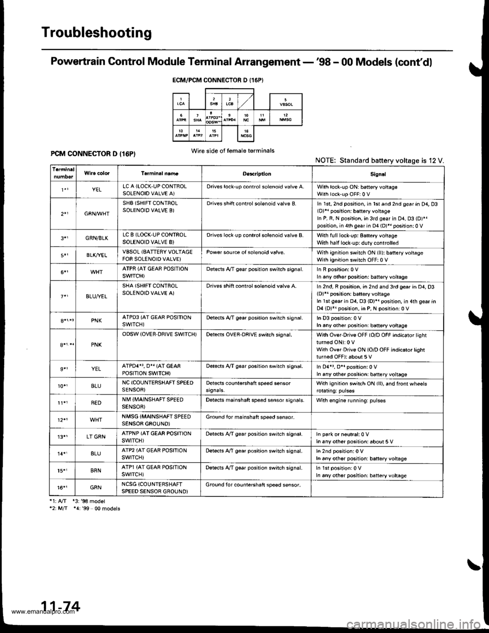
Powertrain Control Module Terminal Arrangement -'98 - 00 Models (cont'dl
PCM CONNECTOR D (16P)NOTE: Standard battery voltage is 12 V.
i1:A/T *3:'98 model'2: M/T *4:'99 00 models
ECM/PCM CONNECTOR D {16P}
Wire side of lemaleterminals
D€s4riptionSign!l
YELLC A {LOCK,UP CONTBOLSOLENOID VALVE A)Oriv€s lock'up conrrol solenoid valve A.With lock-up ON: b6ttery voltagsWith lock-up OFF:0 V
2+1GBN,M/HT
SHB (SHIFT CONTROLSOLENOIO VALVE B)Drives shift controlsolenoid valve B.In 1st, 2nd position, in lst and 2nd gear an D4, D3(D)11 position: battery vohag€In P, R, N position, in 3rd geaf in D1, D3 (D)*.position, in 4th gear in D4 (D)*r positionr0 V
GRN/BLKLC 8 (LOCK,UP CONTROLSOLENOID VALVE B}Drives lock up controlsolenoid valve B.With full lock-up: 8attery voitageWith half lock'uprduty controlled
BLK/YELVBSOL (BATTERY VOLTAGEFOR SOLENOID VALVE}Pow€r source of solenoid valvs.With ignition switch ON (ll): batteryvoltageWith ignition switch OFF| 0 V
ATPR {AI GEAE POSITIONSWITCH)Delscls A/T gear posrtion swirch srgnal.In any other positjon: battsry voltage
BLU,ryEL
SHA (SHIFT CONTROLSOLENOID VALVE A)Drives shift conrrol solenoid valvp A.In 2nd, R position, an 2nd and 3rd ge6r in D4, D3(D)r' posilion: batlery voltageIn 1st gear in 04, 03 {D)}. position, in 4th gear inD4 (D)*. position, in P, N position:0 V
PNKATPD3 (AT GEAR POSITIONswrTcH)Detects A,/T g€ar poshion swirch sign6l.In D3 position:0 Vh any other posiiion: ban€ryvoltage
PNK
ODSW (OVER.DBIVE SWITCH)Detects OVEF-DRIVE swirch sagnal.With Ovor Drivs OFF (O/D OFF indicator lightturned ON): 0 VWilh Ovsr Drivs ON (O/D OFF indicrto.lashtturned OFF): about 5 V
9''YELATPDI}3, O}I {AT GEARPOStTtON SWTTCH)Dot€cts A/T g€ar position swirch signal.In D4r3, O*. position:0 VIn any other posilion: battery voltage
10.,BLUNC (COUNIERSHAFT SPEEDSENSOR)Detscts counl€rshaft speed sensorWith ignition switch ON (ll), and ffonr wheels
REDNM IIVAINSHAFT SPEEDSENSOB)Detects mainshaft speed sensor sign6ls.Wilh engine running: pulses
NMSG {MAINSHAFTSPEEDSENSOB GBOUND)Ground for mainshaft speed sensor-
'13*1LT GRNATPNP (AT GEAR POSITIONswtTcH)Delects A,/T gear position switch signat.In park or n€utral:0 Vh any other posilion: about 5 V
8LUATP2 (AT GEAR POSFIONswrTcH)Dstects A,/T gear position switch signal.h any othsr position: battery voltsgs
15.'BRNATP1 {AT GEAR POSITIONswrTcH)Detscts A/T gear position switch signal.In any other position: htteryvoltage
t6''GRNNCSG {COUNTERSHAFTSPEED SENSOR GROUND}Grouod for counterchaft sp€ed s€nsor.
11-74
www.emanualpro.com
Page 282 of 1395

PGM-FI System
System Description
INPUTS
CKP/TDC/CYP Sensor
CKF Sensor
MAP Sensor
ECT Sensor
IAT Sensor
TP Sensor
Primary HO2S
Secondary H02S
vss
KS*5
BARO Sensor
ELD*6
Starter Signal
ALT FR Signal
Air Conditioning Signal
Ay'T Gear Position Signal*1
Baftery Voltage (lGN.1)
Brake Switch Signal
PSP Switch Signal
Fuel Tank Pressuae Sensor*4. *5
Countershaft Speed Sensor*1
Mainshaft Speed Sensor*r
OVER-DRIVE Switch Signal*s
ENGINE CONTROL MODULE (ECM)/
POWERTRAIN CONTROL MODULE (PCM) OUTPUTS
|iuel 1"j""- Th,rhg ""d Drrafr";-l
Et*-.nt"tdt"cont.orl
to,r*,c;;trffi;]
l.----.---:. .Lrgnrnon |lmrng Lonrror I
Ecir/PcM B*k',p Fr""il]
m;"t-ll-r*'io*l
Fuel Injectors
PGM-Fl Main Relay (Fuel Pump)
MIL
IAC Valve
Ay'C Compressor Clutch Relay
Radiator Fan Relay
Condenser Fan Relay
ALT
tcM
EVAP Purge Control Solenoid
Valve
Primary HO2S Heater
Secondary H02S HeaterEVAP Bypass Solenoid Valve*a *5
EVAP Control Canister Vent Shut
DLC
Lock-up Control Solenoid Valve*l
Shift Control Solenoid Valve*1
Ay'T Clutch Pressure Control
Solenoid Valve*1
D4 Indicator Light'1 *3, *a
D Indicator Light,l *5
OVER-DRIVE OFF Indicator
Lighl*t *:
*1: A/T {3:'97 model'2: M/f +4:'98 model*5: '99 - 00 models"6: USA
PGM-Fl System
The PGM-Fl system on this model is a sequential multiport fuel injection system.
Fuel iniecior Timing and Duration
The ECM/PCM contains memories for the basic discharge durations at various engine speeds and manifold pressure. The
basic discharge duration, after being read out from the memory, is further modified by signals sent from various sensors
to obtain the final discharge duration.
ldle Air Control
ldle Air Control Valve (lAC Valve)
When the engine is cold, the Ay'C compressor is on, the transmission is in gear, the brake pedal is depressed, the P/S load
is high, or the alternator is charging, the ECM/PCM controls current to the IAC Valve to maintain the correct idle speed.
lgnition Timing Control
o The ECM/PCM contains memories for basic ionition timing at various engine speeds and manifold air flow rates.
lgnition timing is also adjusted for engine coolant temperature.
. A knock control system was adopted which sets the ideal ig nition timing for the octane rating of the gasoline used.*s
Other Control Funstions
1. Starting Control
When the engine is started. the ECM/PCM provides a rich mixture by increasing fuel injector duration.
2. Fuel Pump Control
. When the ignition switch is initially turned on (ll). the ECMiPCM suppli€s ground to the PGM-FI main relay that
supplies current to the fuel pump for two seconds to pressurize the fuel system.
. When the engine is running, the ECM/PCM supplies ground to the PGM-FI main relay that supplies current to the
fuel oumo.
. When the engine is not running and the ignition is on, the ECM/PCM cuts ground to the PGM-FI main relay which
cuts current to the fuel pump.
1 1-80
www.emanualpro.com
Page 283 of 1395

Fuel Cut-off Control
. During deceleration with the throttle valve closed, current to the fuel injectors iscutoffto improvefuel economyat
speeds over 970 rpm ('97 - 98 models), 920 rpm ('99 - 00 modelsl.
. Fuel cut-off action also takes place when engine speed exceeds 6,500 rpm ('97 - 98 models), 6900 rpm ('99 - 00
models), regardless of the position of the throttle valve, to protect the engine from over-rewing.
With Ay'T model. the PCM cuts the fuel at engine speeds over 5,000 rpm when the vehicle is not moving.*'�
4,./C Comoressor Clutch Relav
When the ECM/PCM receives a demand for cooling from the air conditioning system, it delays the compressor from
being energized, and enriches the mixture to assure a smooth transition to the Ay'C mode.
Evaporative Emission (EVAP) Purge Control Solenoid Valve
When the engine coolant temperature is above 154"F (68'C), the ECM/PCM controls the EVAP purge control solenoid
valve which controls vacuum to the EVAP purge control canister,
Alternator Control
The system controls the voltage generated at the alternator in accordance with the electrical load and driving mode.
which reduces the engine load to improve the fuel economy.
PCM Fail-saf e/Back-up Functions
1. Fail-safe Function
When an abnormality occurs in a signal from a sensor, the ECM/PCM ignores that signal and assumes a pre-pre
grammed value for that sensor that allows the engine to continue to run.
2. Back-up Function
When an abnormality occurs in the ECM/PCM itself, the fuel injectors are controlled by a back-up circuit independent
of the system in order to permit minimal driving.
3. Self-diagnosis Function IMalfunction Indicator Lamp (MlL)l
When an abnormality occurs in a signal from a sensor, the ECM/PCM supplies ground for the MIL and stores the DTC
in erasable memory. When the ignition is initially turned on {ll), the ECM/PCM supplies ground for the MIL for two
seconds to check the MIL bulb condition.
4. Two Trio Detection Method
To prevent false indications, the Two Trip Detection Method is used for the HO2S*1, fuel metering-related. idle control
system, ECT sensor and EVAP control system self-diagnostic functions. When an abnormality occurs, the ECM/PCM
stores it in its memory. When the same abnormality recurs after the ignition switch is turned OFF and ON (ll) again,
the ECM/PCM informs the driver by lighting the MlL. However, to ease troubleshooting, this function is cancelled
when you jump the service check connector, The MIL will then blink immediately when an abnormality occurs.
5. Two (or Three) Driving Cycle Detection Method {'97 model)
A "Driving Cycle" consists of starting the engine, beginning closed loop operation, and stopping the engine. lf misfir-
ing that increases emissions or EVAP control system malfunction is detected during two consecutive driving cycles.
or TWC deterioration is detected during three consecutive driving cycles, the ECM/PCM turns the MIL on. However, to
ease troubleshooting, this function is cancelled when you jump the service check connector. The MIL will then blink
immediately when an abnormality occurs.
*1: '97 - 98 models*2: '99 - 00 models
5.
www.emanualpro.com
Page 284 of 1395
PGM-FI System
Powertrain Control Module {PCM} -'97 Model
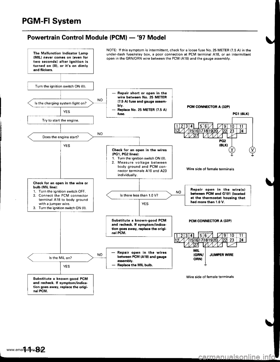
NOTE: lf this symptom is intermiftent, check for a loose fuse No. 25 METER (7.5 A) in theunderdash f{rse/relay box, a poor connection at PCM terminal A18, or an intermittentopen in the GRN/ORN wire between the PCM (A18) and the gauge assembly.
PCM OON ECTOR A {32P}
Wire side of female terminals
PCM CONNECTOR A {32PI
Wire side ot temale terminals
11-42
The Malfunction lndicator LamD(MlL) nev6r comes on {even lortwo seconds) after ignition isturned on (lll, or it's on dimlyand flickers.
Turn the ignition switch ON {ll}.
- Rep.ir short or opon in thowire batween No. 25 METER(7.5 Alfuso and gauge a$€m-bty.- R6pl.c€ No. 25 METER 17.5 Alfus€.
ls the charging system light on?
Try to stan the engine.
Does the engine start?
Chock tor.n open in th6 wire3{PG1, PG2linesl:1. Turn the ignition switch ON (ll).2. Measure voltage betweenbody ground and PCM con-nector terminals A10 and A23individually.
Check for an op€n in the wir6 orbulb (MlL lin€l:1. Turn the ignition switch OFF.2. Connect the PCM connectorterminal A18 to body groundwith a iumper wire.3. Turn the ignition switch ON {ll).
n€peir open in tho wirelslhwoon PCM and Glol (loc!t.d
at thc tha.mo3tat houling thrthtd moro th.n 1.0 V.
ls thore l€ss than 1.0 V?
Substituto . known-good PCMand r€check. ll symptom/indica-tion goss away, rcplaca the origi-nal PCM.
- R6pai. open in th. wileibelwoon rcM lAl8l dnd g.ugea3rombly.- Roolac€ the MIL bulb.
ls the MIL on?
Substitut6 a known-good PCMand rocheck. ll 3ymptom/indica-tion goes away, replace the o.igi-n.l PCM.
PGl IBLKI
www.emanualpro.com
Page 285 of 1395
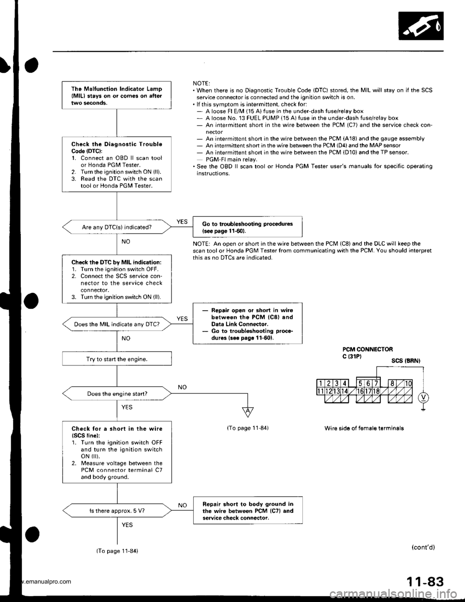
NOTE:. When there is no Diagnostic Trouble Code (DTC) stored, the MIL will stay on if the SCSservice connector is connected and the ignition switch is on.. lf this svmotom is intermittent, check for:- A loose Fl E/M (15 Aifuse in the underdash tuse/relay box- A loose No. 13 FUEL PUMP {15 A) fuse in the under-dash fuse/relay box- An intermittent short in the wire between the PCM (C7) and the service check con-
- An intermittent short in the wire between the PCM (A18) and the gauge assembly- An intermittent shon in the wire betlveen the PCM (D4) and the MAP sensor- An intermiftent short in the wire between the PCM {D10) and the TP sensor.PGM-Fl main relay.'See the OBD ll scan tool or Honda PGM Tester user's manuals lor specilic operatinginstructions,
NOTE: An open or short in the wire between the PCM (C8) and the DLC will keep thescan tool or Honda PGM Tester lrom communicating with the PCM. You should ioterpretthis as no DTCS are indicated.
PCM CONNECTORc l3lPl scs .BRNI
lTo page 11 84)Wire sid6 of f€male terminalg
(cont'dl
11-83
The Malfunciion lndicator Lamo{MlL) stavs on o. comes on afteltwo seconds,
Check the Oiegnosiic TroubleCode (DTC):
1. Connect an OBD ll scan toolor Honda PGM Tester.2. Turn the ignition switch ON 1lli.3. Read the DTC with the scantool or Honda PGII Tester.
Go to troubleshooting procedures(s€€ page 11501.Are any DTCIs) indicated?
Ch6ck lh6 DTC by MIL indication:1. Turn the ignition switch OFF.2. Connect the SCS service con-nector to the service checkconnector.3. Turn the ignition switch ON (ll).
- Repair opon or short in wi.6between the PCM (C8) andData Link Connector.- Go to troubloshooting proce-
dur€s {3ee page 11-601.
Does the MIL indicate any DTc?
Try to start the engine.
Does the engine start?
Check tor a short in the wire{SCS line):1. Turn the ignition switch OFFand turn the ignition switchoN flt).2. Measure voltage between thePCM connector terminal C7and body ground.
Repair short to body ground inthe wire between PCM lCTl andservice check connector.ls there approx. 5 V?
(To page 1'l-84)
www.emanualpro.com
Page 286 of 1395
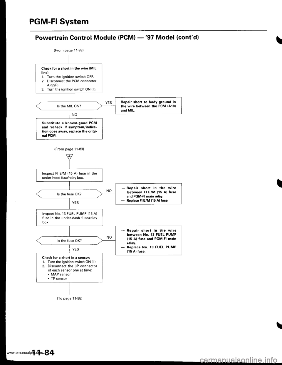
Powertrain Control Module (PCM) -'97 Model (cont'dl
(From page 11 83)
Check for a short in the wire (MlL
line):1. Turn the ignition switch OFF.2. Disconnect the PCM connectorA {32P).3. Turn the ignition switch ON (ll).
Repair short to body ground inthe wire between the PCM {418}and MlL.ls the MIL ON?
Substitute a known-good PCMand recheck. lf symptom/indica-tion goes away. replace the origi-nal PCM.
Inspect Fl E/M (15 A) fuse in theundeFhood fuse/relay box.
- Reoair shod in the wirebetween Fl E/M {15 A} fuseand PGM-FI main relav.- Replace FIE/M 115 A)fuse.
Inspect No. 13 FUEL PUMP (15 Aifuse in the underdash fuse/relay
- Repair short in lh€ wirebolween No. 13 FUEL PUMP
115 A) Iuse and PGM-FI main
- Replace No. 13 FUEL PUMP
115 A) fuse.
Check loJ a short in a sensor:1. Turn the ignit;on switch ON (ll).
2. Disconnect the 3P connectorof each sensor one at time:. MAP sensor
(To page 11-85)
11-84
www.emanualpro.com