Page 965 of 1395
Troubleshooting
ABS Indicator Does Not Come On (cont'd)
(From page 19'41)
GAUG€ ASSEMBLY 5P CONNECTOR
---g-l1 t/l3_l/ | 5 |JUMPER I GND IBLK}wrBE IL
Wire side of female terminals
Check the gruge essembly:1. Turn the ignition switch OFF.2. Connect the gauge assembly5P connector,3. Connect the terminal No. 3 tobody ground with a jumper
4. Turn the ignition switch ON (ll).
Reolace the ABS indicator drivecircuit in the gaug€ ass€mbly.Does the ABS indicator come on?
.Repair open in the wirebetween the gauge assemblyand body ground.. Repair poor ground {G401,c102l-
19-42
www.emanualpro.com
Page 967 of 1395

Troubleshooting
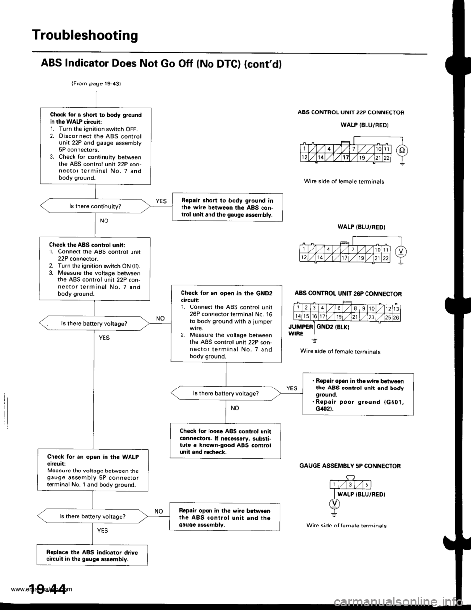
ABS Indicator Does Not Go Off (No DTC) (cont'dl
ABS CONTROL UNIT 22P CONNECTOR
WALP {BLU/REDI
Wire side of female terminals
JUMPCRWIREGND2IBLKI
GAUGE ASSEMBLY 5P CONNECTOF
(From page 19,43)
Check tor a short to body groundin the WALP circuil:1. Turn the ignition switch OFF.2. Disconnect the ABS controlunit 22P and gauge assembly5P connectors.3. Check lor continuity betweenthe ABS control unit 22P con-nector terminal No. 7 andbody ground.
Repair short to body ground inthe wire between the ABS con-t.ol unh and the gauge assembly.
Check the ABS control unit:1. Connect the ABS control unit22P connector.2. Turn the ignition switch ON (ll).3. Measure the voltage betweenthe ABS control unit 22P con-nector terminal No. 7 andbody ground.Check tor an open in the GND2circuit:1. Connect the ABS control unit26P connecto. terminal No. 16to body ground with a jumper
2. Measure the voltage betweenthe ABS control unit 22P con-nector terminal No. 7 andbody ground.
ls there battery voltage?
. Repeir op6n in th6 wire ttetweenthe ABS control unit and bodyground.. Rep.ir poor ground {G401,G4021.
Check lor loose ABS control unhconnectors. lf necesssry, substi-tuie e lnown-good ABS controlunit and recheck.Check tor an open in the WALPcircuit:Measure the voltage between thegauge assembly 5P connectorterminal No. 1 and body ground.
Repair op6n in the wi.e botw€enthe ABS control unit and th€gau9e ass€mbly.
ls there battery voltage?
Replaco the ABS indicator drivecircuit in the gauge assembly.
ABS CONTROL UNIT 26P CONNECTOR
Wire sade of female terminals
WALP IBLU/FEDI
19-44
www.emanualpro.com
Page 1092 of 1395
Special Tools
Rel. No. I Tool NumberDescriptionOty I Page Relerence
.o
6,
@
@
07JGG - 001010A
07sAz - 001000A
07947 - 6340300
07965 - 6920500
Belt Tension Gauge
Backprobe Set
Driver Attachment
Hub Assembly Guide Attachment
1
2
1
1
22-69
22-33,36,37
22-66
22-61
* Included in the Belt Tension Gauge Set, T/N 07TGG - 001000A
t
o
22-2
www.emanualpro.com
Page 1184 of 1395

Connector ldentification and Wire Harness Routing
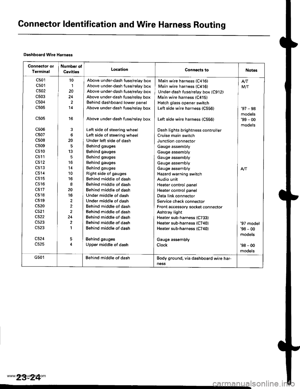
Dashboard Wire Harness
Connector ol
Terminal
Numb€r of
CavitiesLocationConngcts toNotes
c501
c501
c502
c503
c504
c505
c506
c507
c508
c509
c510
c511
c512
c514
c518
c519
c520
c521
c524
10
1
20
14
16
6
20
13
5
t6
14
10
to
20
16
2
24
2
1
5
Above under-dash fuse/relay box
Above under-dash fuse/relay box
Above under-dash fusehelay box
Above under-dash fuse/relay box
Behind dashboard lower panel
Above under-dash fuse/relay box
Above under-dash fuse/relay box
Left side of steering wheel
Left side of steering wheel
Under left side of dash
Behind gauges
Behind gauges
Behind gauges
Behind gauges
Behind gauges
Right side of gauges
Behind middle of dash
Behind middle of dash
Behind middle of dash
Under middle of dash
Under middle of dash
Behind middle of dash
Behind middle of dash
Behind middle of dash
Behind middle of dash
Behind middle of dash
Behind gauges
Upper middle of dash
Main wire harness (C416)
Main wire harness (C416)
Under-dash fuse/relay box 1C912)
Main wire harness (C415)
Hatch glass opener switch
Left side wire harness (C556)
Left side wire harness (C556)
Dash lights brightness cont.oller
Cruise main switch
Junction connector
Gauge assembly
Gauge assembly
Gauge assembly
Gauge assembly
Gauge assembly
Hazard warning switch
Audio unit
Heater control panel
Heater control panel
Data link connector
Service check connector
Front accessory socket connector
Ashtray light
Heater sub-harness (C733)
Heater sub-harness {C740}
Heater sub-harness (C740)
Gauge assembly
Clock
'97 - 98
models'99 - 00
models
Mir
A/r
'97 model'98 - 00
mooets
'98 - 00
models
G501Behind middle of dashBody ground, via dashboard wire har-
ness
23-24
www.emanualpro.com
Page 1205 of 1395

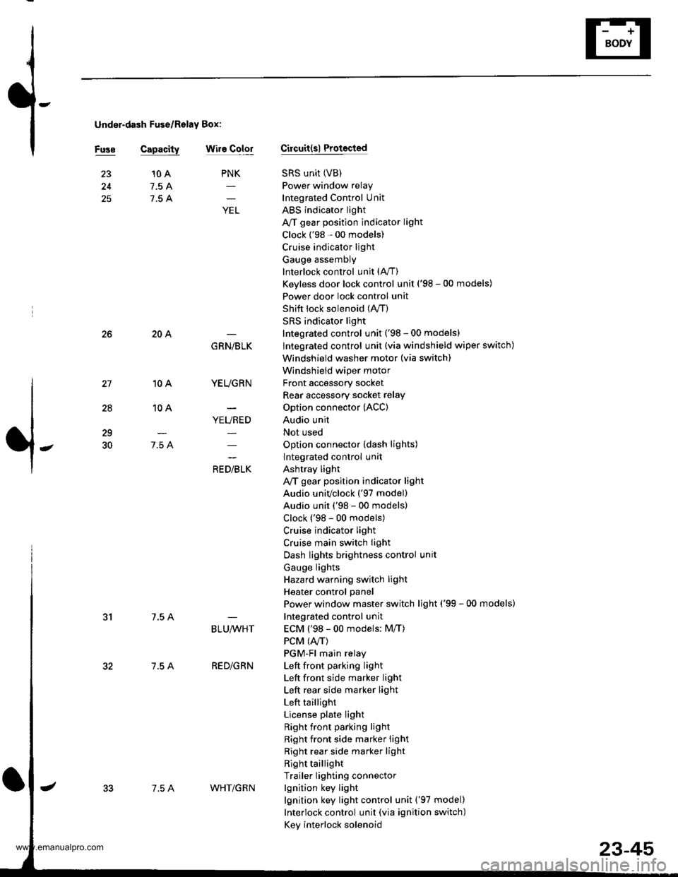
under-dash Fuse/Relay Box:
Fuse Capacitywir6 ColorCircuit(sl Protocted
SRS unit (VB)
Power window relay
Integrated Control Unit
ABS indicator light
A/T gear position indicator light
Clock ('98 - 00 models)
Cruise indicator light
Gauge assembly
Interlock control unit (A,/T)
Keyless door lock control unit ('98 - 00 models)
Power door lock control unit
Shift lock solenoid (lVT)
SRS indicator light
Integrated control unit ('98 - 00 models)
Integrated control unit (via windshield wiper switch)
Windshield washer motor (via switch)
Windshield wiper motor
Front accessory socket
Rear accessory socket relay
Option connector (ACC)
Audio unit
Not used
Option connector (dash lights)
Integrated control unit
Ashtray light
A,/T gear position indicator light
Audio univclock ('97 model)
Audio unit ('98 - 00 models)
Clock ('98 - 00 models)
Cruise indicator light
Cruise main switch light
Dash lights brightness control unit
Gauge lights
Hazard warning switch light
Heater control panel
Power window master switch light ('99 - 00 models)
Integrated control unit
ECM ('98 - 00 models: M/T)
PCM (4./T)
PGM-Fl main relay
Left front pa.king light
Left front side marker light
Left rear side marker light
Left taillight
License plate light
Right front parking light
Right front side marker light
Right rear side marker light
Right taillight
Trailer lighting connector
lgnition key light
lgnition key light control unit ('97 model)
Interlock control unit (via ignition switch)
Key interlock solenoid
25
PNK
;
10 A
7.5 A
7.5 A
28
10A
10A
7.5 A
204
7.5 A
7.5 A
GRN/BLK
YEUGRN
YEURED
a, olrL"
29
30
BLU,ryVHT
RED/GRN
7.5 AWHT/G R N
23-45
www.emanualpro.com
Page 1215 of 1395
Gauge Assembly
Component Location Index
SRS components are located in this area. Review the SRS component locations, precautions, and procedures in the SRS
section {24} before performing repairs or service.
I x 1.25 mm24 N.m {2.4
VEHICLE SPEED SENSOF {VSS'Troubleshooting, page 23-62
GAUGE ASSEMBLYGau ge/lndicator/TerminalLocation Index, page 23-56Bulb Locations, page 23-57Removal, page 23-61
J-
FUEL GAUGE SENDING UNITSee section 1 l
PARKING BRAKE SWITCH
COOLANT TEMPERATURE GAUGESENDING UNITBRAKE FLUID LEVEL SWITCH
ENGINE OIL PRESSURE SWITCH
www.emanualpro.com
Page 1216 of 1395
Gauge Assembly
Gau ge/lndicator/Terminal Location Index
CONNECTOR "A"
{A/T GEAB POSITION INDICATOR)
CONNECTOR "D-
{ABS INDICATOR)CONNECTOR "E"
{CBUISE INDICATOR'CONNECTOR "F"
{SRS INDICATOR}
SPEEDOMETER:Indicates 60 km/h at 637 rpm or60 mph at 1,026 rpm ofthevehicle speed sensor (VSS).
TACHOMETER:lndicates 100 rpm at200 pulses per minuteof the ignition controlmodule (lCM).
23-56
a1___-__-____>816
JilililIJililil1
cl --------->cl3
JililtHililL
,
.. "€""^
o o ue ou
t)1- --->t)5E1- - -->E5Fl---->F5
oo/ \oo
www.emanualpro.com
Page 1218 of 1395
Gauge Assembly
Circuit Diagram
BATTERY
@*"
UNOER.IIOOD FUSE/RELAY 8OX
No.41 (100A) No.42 (40A)
UNOER_DASHFUSEiNELAY BOX
|
'''
IRED
-I
DASH LIGHTSBRIGHTNESSCONTROLLER
l-8LK
G401G4A2
CRUISECONTROLUNIT
23-58
JALTERNATOR
| 0l
IBLU/RED
-I
ABSCONTROLUNIT
JSRS UNIT
YEL
E5 GAUGE ASSEMSLY
www.emanualpro.com