1998 HONDA CR-V torque mount
[x] Cancel search: torque mountPage 756 of 1395
Transfer Assembly
Reassembly
NOTE:
. While reassembling the transfer assembly:. Check and adjust the transfer gear tooth contact.. Measure and adjust the transfer gear backlash.. Check and adjust the tapered roller bearing stan-
ing torque.
. Coat all pans with ATF during reassembly.. Replace the tapered roller bearing and the bearing
outer race as a set if either part is replaced.. Replace the transfer drive gear and the transfer dri-ven gear shaft as a set if either part is replaced.
Outline of Assembly
1.Select the 35 mm thrusi shim.
Psrtorm this procedute if the transter driven g€ar
shaft or the tapered roller bearing on the transfer
driven gear shaft is replaced.
Prea$emble the parts to check and adiust transtelgear backlash and transfer gear tooth contact.
Disassemble the parts, then assemble the translerdriven gsar shaft and its related pans.
2.
3.
4. Measure and adjust the starting torque oI the
transfer driven gear shaft tapered roller bearing.
5. Assemble the transfer shaft and its related parts.
6. Measure and adiust the total starting torque.
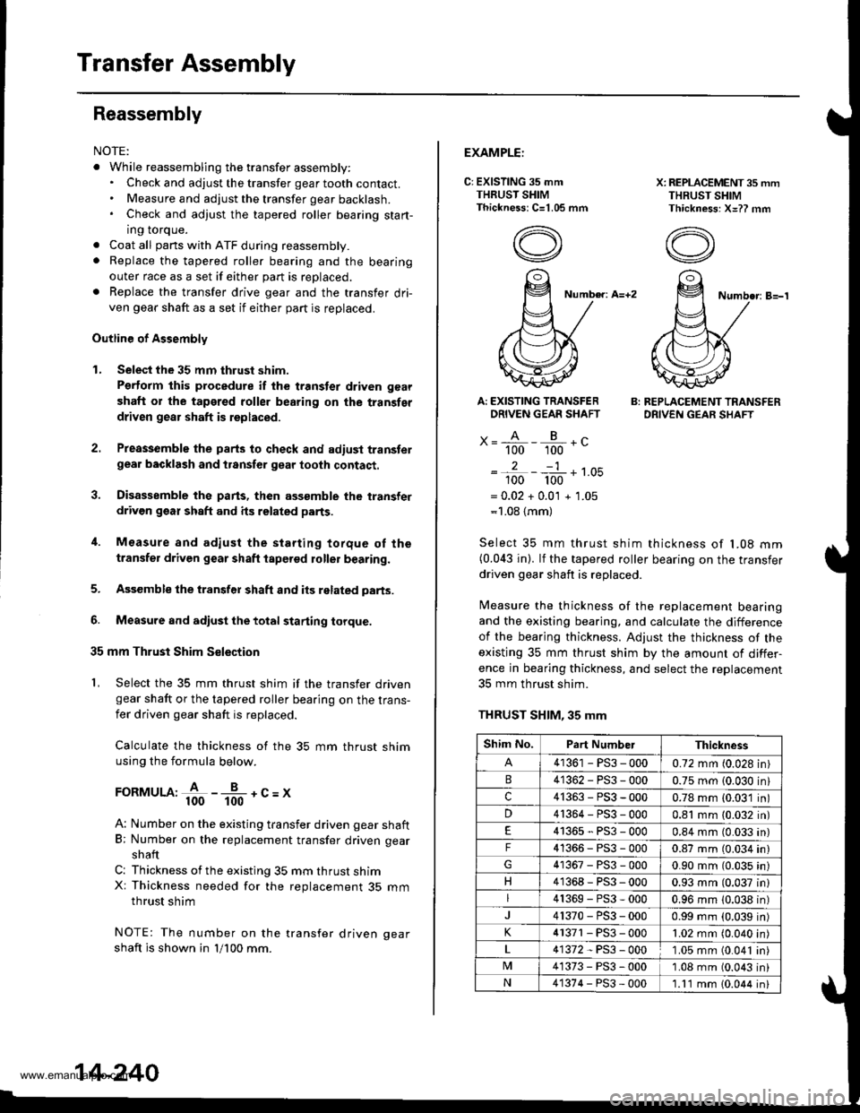
35 mm Thrust Shim Selection
L Select the 35 mm thrust shim if the transfer drivengear shaft or the tapered roller bearing on the trans-
fer driven gear shaft is replaced.
Calculate the thickness of the 35 mm thrust shimusing the formula below.
FoRMULA:+ -*-+c=x
A: Number on the existing transfer driven gear shaft
B; Number on the replacement transfer driven gear
shaft
C: Thickness ofthe existing 35 mm thrust shimX: Thickness needed for the replacement 35 mmthrust shim
NOTE: The number on the transfer driven oear
shaft is shown in 'll100 mm.
14-240
EXAMPLE:
C: EXISTING 35 mmTHRUST SHIMThickness: C=1.05 mm
X: REPLACEMENT 35 mmTHRUST SHIMThickness: X=?? mm
Number: A=+2Numbe.: B=-'l
Ar EXISTING TRANSFERDRIVEN GEAR SHAFT
x= A - B .c" 100 100 -
2-1
100 100 '-
= 0.02 + 0.0'l + 1.05=1.08 {mm)
B: REPLACEMENT TRANSFERDRIVEN GEAR SHAFT
Select 35 mm thrust shim thickness of l�08 mm(0.043 in). lf the tapered roller bearing on the transfer
driven gear shaft is replaced.
Measure the thickness of the replacement bearingand the existing bearing, and calculate the difference
of the bearjng thickness. Adjust the thickness of the
existing 35 mm thrust shim by the amount of differ-
ence in bearing thickness, and select the replacement
35 mm thrust shim.
THRUST SHIM, 35 mm
Shim No.Part NumberThickness
41361 - PS3 - 0000.72 mm (0.028 in)
41362-PS3-0000.75 mm {0.030 in}
c41363-PS3-0000.78 mm (0.03'1 in)
D41364-PS3-0000.81 mm (0.032 in)
41365-PS3-0000.84 mm (0.033 an)
F41366-PS3-0000.87 mm (0.034 in)
41367-PS3-0000.90 mm (0.035 in)
H41368-PS3-0000.93 mm (0.037 in)
41369-PS3-0000.96 mm 10.038 in)
41370-PS3-0000.99 mm (0.039 in)
K4 r371 - PS3 - 0001.02 mm (0.040 in
41372-PS3-0001.05 mm (0.041 in
M41373-PS3-0001.08 mm (0.043 in
N41374-PS3-000'1.11 mm 10.044 in
www.emanualpro.com
Page 769 of 1395
17.
18.
19.
20.
21.
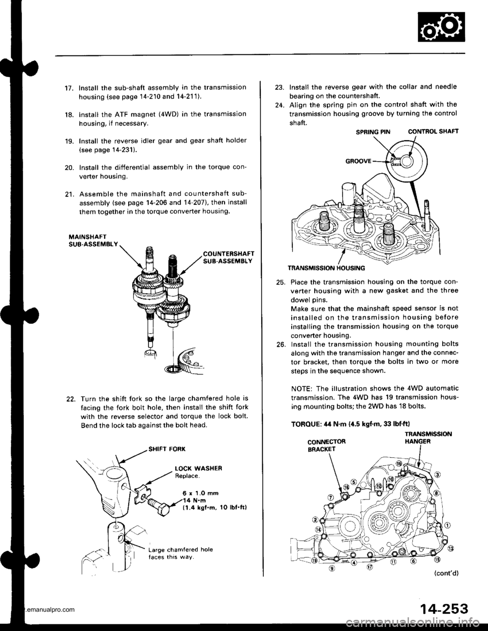
Install the sub-shaft assembly in the transmission
housing (see page 14-210 and 14-2'111.
lnstall the ATF magnet (4WD) in the transmission
housing, if necessary.
Install the reverse idler gear and gear shaft holder
(see page 14-231).
Install the differential assembly in the torque con-
verter housing.
Assemble the mainshaft and countershaft sub-
assembly (see page 14-206 and 14 207],, then install
them together in the torque converter houslng.
COUNTERSHAFTSUB-ASSEMBLY
Turn the shift fork so the large chamfered hole is
facing the fork bolt hole. then install the shift fork
with the reverse selector and torque the lock bolt.
Bend the lock tab against the bolt head.
SHIFI FORK
LOCK WASHERBeplace.
6 r 'l.O mm4 N.m(1.4 ksl.m. 1O lbt.ft)
Large chamfered hole
24.
Install the reverse gear with the collar and needle
bearing on the countershatt.
Align the spring pin on the control shaft with the
transmission housing groove by turning the control
shaft.
SPRING PIN CONTROL SHAFT
TRANSMISSION HOUSING
25. Place the transmission housing on the torque con-
verter housing with a new gasket and the three
dowel pins,
Make sure that the mainshaft speed sensor is not
installed on the transmission housing before
installing the transmission housing on the torque
converter housing.
26. Install the transmission housing mounting bolts
along with the transmission hanger and the connec-
tor bracket, then torque the bolts in two or more
steos in the seouence shown.
NOTE: The illustration shows the 4WD automatic
transmission. The 4WD has 19 transmission hous-
ing mounting bolts; the 2WD has 18 bolts.
TOROUE: 44 N.m {,[.5 kgf.m, 33 lbf'ft)
{cont'd)
14-253
SPRING PIN
TNANSMISSION
www.emanualpro.com
Page 775 of 1395
Transmission
1.
lnstallation
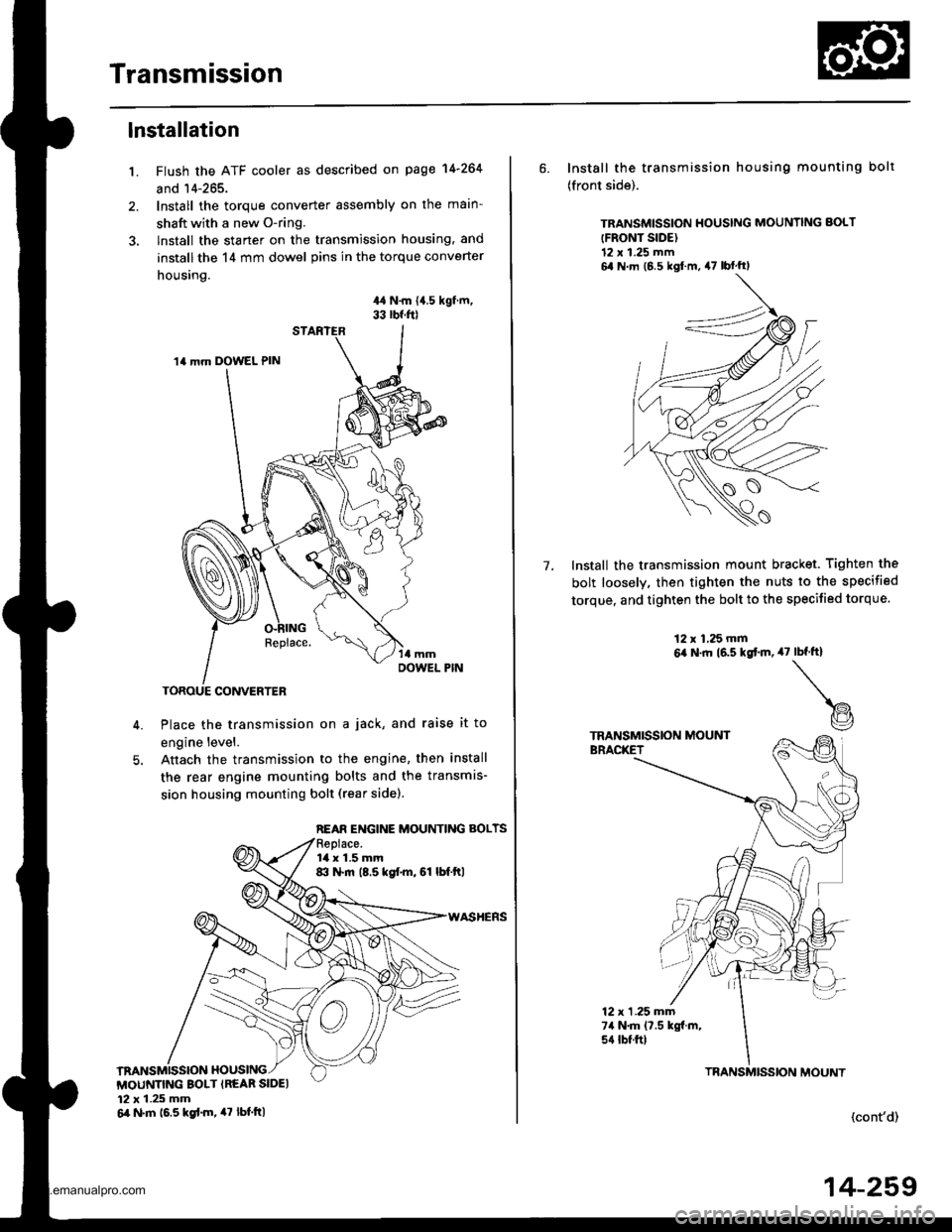
Flush the ATF cooler as described on page 14-264
and 14-265.
Install the torque converter assembly on the main-
shaft with a new O-ring.
lnstall the starter on the transmission housing, and
install the 14 mm dowel pins in the torque converter
housing.
44 N.m {{.5 kgf.m,33 rbf.f0
Place the transmission on a jack, and raise it to
engine level.
Anach the transmission to the engine, then install
the rear engine mounting bolts and the transmis-
sion housing mounting bolt (rear sidel.
14 mm DOWEL PIN
REAR ENGINE MOUNTING BOLTS
la x 1.5 mm8:l N.m (8.5 kgf.m, 61 lbf.ftl
MOUNTING BOLT {REAR SIDEI12 x 1.25 mm6il N.m 16.5 kgd.m, 47 tbt.ttl
6. Install the transmission housing mounting bolt
(front side).
TRANSMISSION HOUSING MOUNNNG BOLT
{FRONT SIDE)12 x 1.25 mm6,1 N m (6 5 kgl m, 47 lbf'ftl
Install the transmission mount bracket. Tighten the
bolt loosely, then tighten the nuts to the specified
torque, and tighten the bolt to the specified torque.
7.
12 x 1,25 mm6,a N.ft (6.5 kgtm,47rbf.ft)
t@
TRANSMISSION MOUNTBRACKET
12 x 1 .25 mm74 N.m (7.5 kgf.m,s{ tbtftl
(cont'd)
TBANSMISSION MOUNT
14-259
www.emanualpro.com
Page 776 of 1395
Transmission
Installation (cont'dl
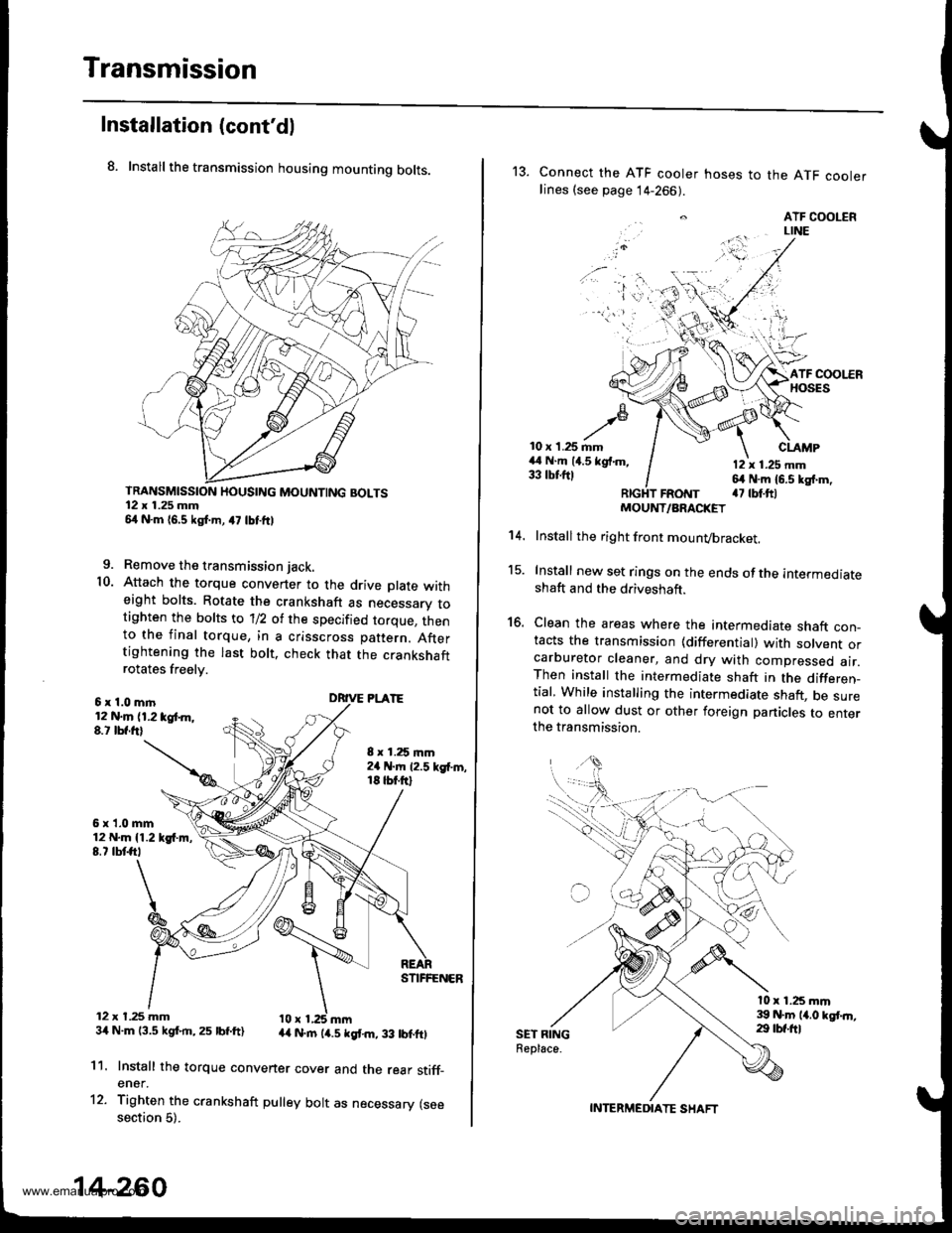
8. Install the transmission housing mounting bolts.
TRANSMISSION HOUSING MOUNTING BOLTS12 x 1.25 mm54 N.m 16,5 kgf.m, a7 lbtftl
9. Remove the transmission jack.
10. Attach the torque convener to the drive plate witheight bolts. Rotate the crankshaft as necessarv totighten the bolts to 'll2 of the specified torque, thento the final torque, in a crisscross pattern. Aftertightening the last bolt. check that the crankshaftrotates freelv.
6x1.0mln12 N.m (1.2 tgt m,8.t lbf.frl
6x1.0mm12 N.m {1.219{.m,8.7 tbtft,
12 x t.25 mm34 N.m 13.5 kgf.rn,25 lbf.ft)
8 x 1.25 mm2a N.m 12.5 kgf'm,18 tbt.ftl
DRIVE PLATE
STIFFENER
44 N.rn (4.5 kgt m, 33 lbtftl
11.
12.
Install the torque convener cover and the rear stiff_ener.
Tighten the crankshaft pulley bolt as necessary (seesection 5).
14-260
13. Connect the ATF cooler hoses to the ATF coolerlines (see page 14-266).
. ATF COOLERLINE
'i 'l'r',:,.) -
10 x 1.25 mm44 N.m (4.5 kgf.m,33 tbtftl
CLAMP
12 x 1.25 mm64 N.m 16.5 kg{.m,a7 tbt.ftlFRotrtT
15.
16.
't 4.
SET RINGReplace.
MOUNT/ARACKET
Install the right front mounvbracket.
Install new set rings on the ends of the intermediateshaft and the driveshaft.
Clean the areas where the intermediate shaft con_tacts the transmission {differential) with solvent orcarburetor cleaner, and dry with compressed air.Then install the intermediate shaft in the differen_tial, While installing the intermediate shaft, be surenot to allow dust or other foreign panicles to enterthe transmission.
l0 x 1.25 mm39 N.m 14.0 kgt.n,29 tbf.ftl
INTERMEDIATE SHAFT
www.emanualpro.com
Page 803 of 1395
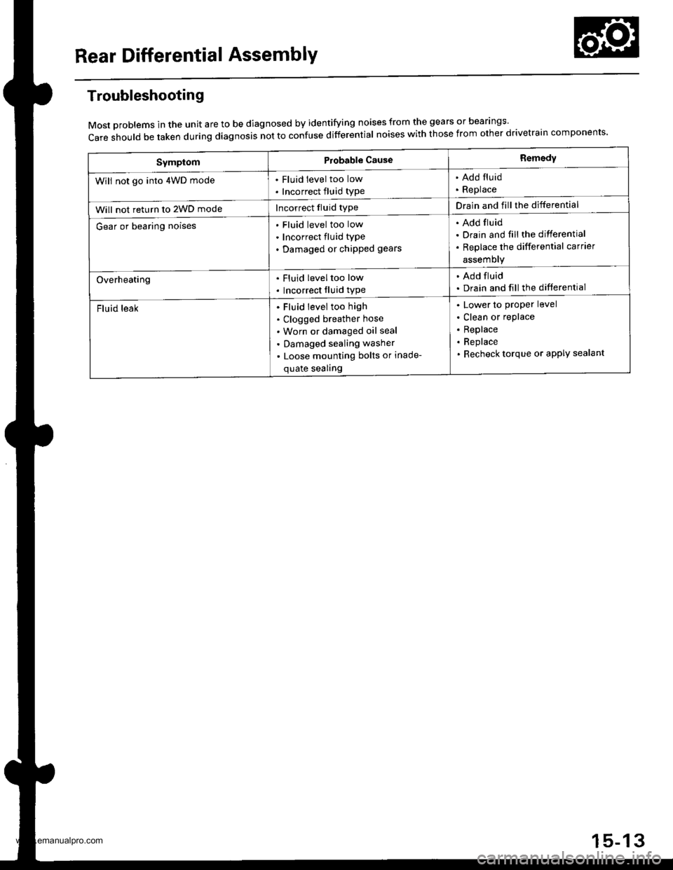
Rear Differential AssemblY
Troubleshooting
Most problems in the unit are to be diagnosed by identifying noises from the gears or bear'ngs'
care should be taken during diagnosis not to confuse differential noises with those from other drivetra'n components'
SymptomProbable CauseRemedy
Will not go into 4WD mode. Fluid level too low
. Incorrect fluid type
. Add fluid. Replace
Will not return to 2WD modeIncorrect fluid typeDrain and fill the differential
Gear or bearing noisesFluid level too low
Incorrect fluid type
Damaged or chipped gears
Add fluid
Drain and fill the differential
Replace the differential carrier
assemory
Overheating. Fluid leveltoo low
. Incorrect fluid type
. Add fluid. Drain and fill the differential
Fluid leakFluid level too high
Clogged breather hose
Worn or damaged oil seal
Damaged sealing washer
Loose mounting bolts or inade-
quate sealing
Lower to proper level
Clean or replace
Replace
Replace
Recheck torque or aPPIY sealant
15-13
www.emanualpro.com
Page 843 of 1395
Rear Driveshafts
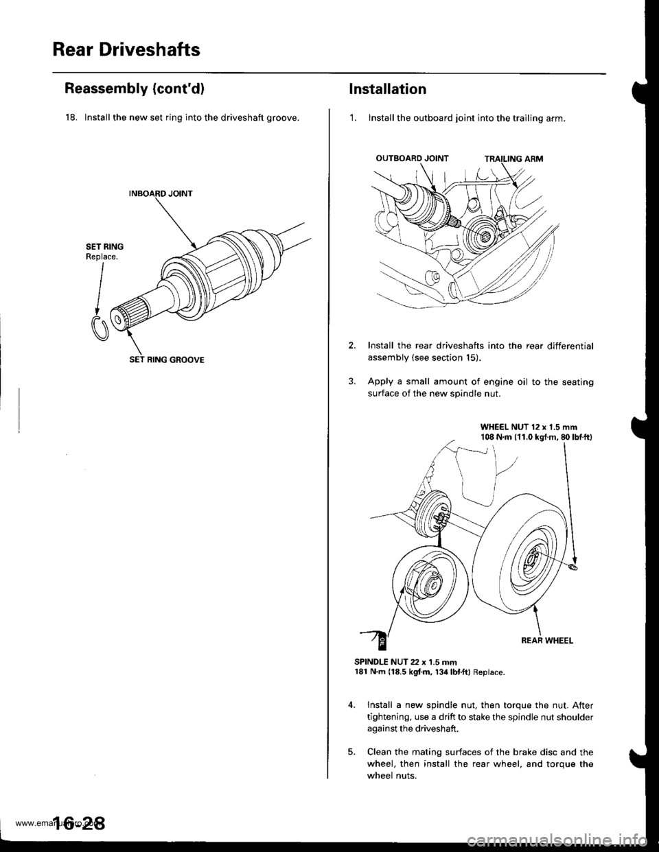
Reassembly (cont'd)
18. Install the new set ring into the driveshaft groove.
SET RINGReplace.
I
CI
SET RING GROOVE
16-2A
lnstallation
'1. lnstall the outboard joint into the trailing arm.
Install the rear driveshafts into the rear differential
assembly (see section 15).
Apply a small amount of engine oil to the seating
surface of the new spindle nut.
SPINDLE NUT 22 x 1.5 mm181 N.m (18.5 kgf.m, 134lbl.ftl Replace.
Install a new spindle nut, then torque the nut. After
tightening, use a drift to stake the spindle nut shoulder
against the driveshaft.
Clean the mating surfaces of the brake disc and the
wheel, then install the rear wheel, and torque the
wheel nuts.
WHEEL NUT 12 x 1.5 mm108 N.m (11.0 kgt.m, 80lbtftl
www.emanualpro.com
Page 892 of 1395
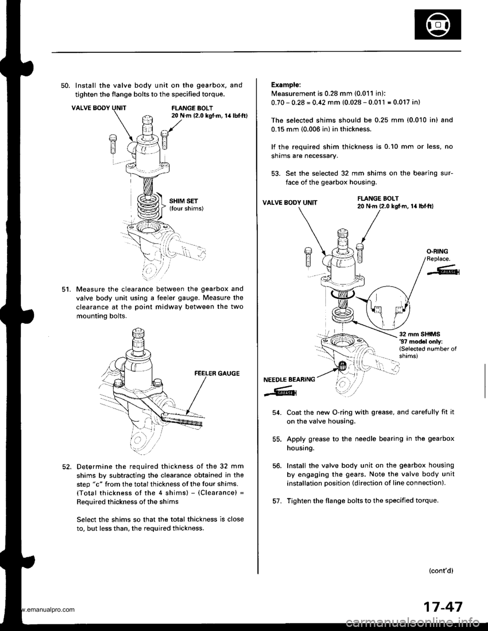
50. Install the valve body unit on the gearbox. and
tighten the flange bolts to the specified torque.
VALVE BODYFLANGE BOLT20 N.m 12.0 kgt.m, 14lbtft)
ct.
SHIM SET(four shims)
Measure the clearance between the gearbox and
valve body unit using a feeler gauge. Measure the
clearance at the poinl midway between the two
mounting bolts.
GAUGE
Determine the required thickness of the 32 mm
shims by subtracting the clearance obtained in the
step "c" from the total thickness of the four shims.
(Total thickness of the 4 shims) - (Clearance) =
Reouired thickness of the shims
Select the shims so that the total thickness is close
to, but less than, the required thickness.
Example:
Measurement is 0.28 mm (0.011 in);
0.70-0.28=0.42 mm (0.028-0.011 = 0.017 in)
The selected shims should be 0,25 mm (0.010 inl and
0.15 mm (0.006 in) in thickness.
lf the required shim thickness is 0.10 mm or less, no
shrms are necessary.
53. Set the selected 32 mm shims on the bearing sur-
face of the gearbox housing.
VALVE BODY UNITla lbl.frl
Coat the new O-ring with grease, and carefully fit it
on the valve housing.
Apply grease to the needle bearing in the gearbox
housing.
Install the valve body unit on the gearbox housing
by engaging the gears. Note the valve body unit
installation position (direction of line connection).
Tighten the flange bolts to the specified torque.
(cont'd)
FLANGE BOLT20 N.m (2.0 kgf.m,
/a)E?
E
O.RINGReplace.
-6{
NEEDLE BEARING
-6lr
54.
56.
57.
17-47
www.emanualpro.com
Page 907 of 1395
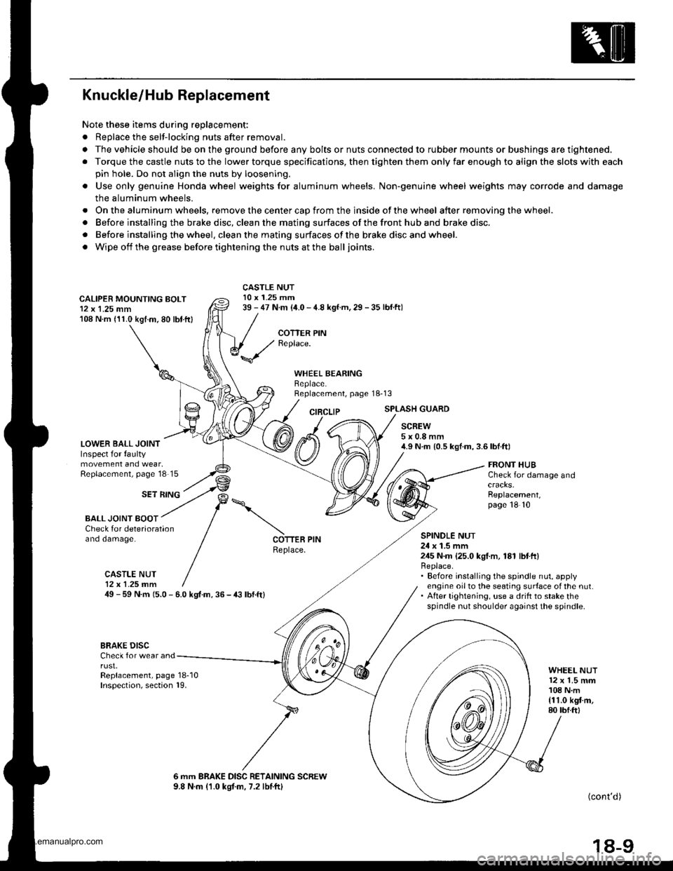
Knuckle/Hub Replacement
Note these items during replacement:
. Replace the selt-locking nuts after removal.
. The vehicle should be on the ground before any bolts or nuts connected to rubber mounts or bushings are tightened.
. Torque the castle nuts to the lower torque specifications, then tighten them only far enough to align the slots with each
pin hole. Do not align the nuts by loosening.
o Use only genuine Honda wheel weights for aluminum wheels. Non'genuine wheel weights may corrode and damage
the aluminum wheels.
. Onthealuminum wheels, remove the center cap from the inside of the wheel after removing the wheel.
. Before installing the brake disc, clean the mating surfaces of the front hub and brake disc.
. Before installing the wheel. clean the mating surfaces ofthe brake disc and wheel.
. Wipe off the grease before tightening the nuts at the balljoints.
CALIPER MOUNTING BOLT12 x 1.25 mm108 N.m (11.0 kgtm.80 lbt.ftl
LOWER BALL JOINTInspect for faultymovement and wear,Replacement, page'18 15
CASTLE NUT10 x 1.25 mm39 - 47 N.m (i1.0 - 4.8 kgf.m, 29 - 35 lbf.ftl
COTTER PINReplace.
WHEEL BEARINGBeplace.Replacement, page 18-13
CIRCLIPSPLASH GUARD
SCREW5x0.8mm4.9 N.m {0.5 kgf.m,3.6lbf.ft)
SET RING
FRONT HUBCheck for damage and
Replacement,page 18 10
BALL JOINT BOOTCheck for deteriorationano oamage.SPINOLE NUT24 x 1.5 mm245 N.m {25.0 kgI.m, 181 lbtft}Replace.. Before installing the spindle nut, applyengine oil to the seating surface of the nut.. After tightening, use a drift to stake thespindle nut shoulder against the spindle.
COTTER PINReplace.
CASTLE NUT12x 1.25 fim49 - 59 N.m 15.0 - 6.0 kgt.m. 36 - € lbf.ft)
BRAKE DISCCheck for wear andrust.Replacement, page 18-10Inspection, section 19.
WHEEL NUT12 x 1.5 mm108 N.m{11.0 kgt m,80 tbf.ftl
6 mm BRAKE DISC RETAINING SCREW9.8 N.m (1.0 kgtm, 7.2 lbtftl(cont'd )
18-9
www.emanualpro.com