Page 575 of 1395
PCM Reset Procedure
'1. Turn the ignition switch off
2. Remove the BACK UP fuse (7.5 A) from the under-hood fuse/relay box for 10 seconds to reset the PCM.
NOTE:
. Disconnecting the BACK Up fuse also cancels the radio preset stations and clock setting Make note of the radio
presets before removing the fuse so you can reset them
. The PCM memorv can also be cleared by using the OBD ll Scan Tool or Honda PGM Tester'
UNDER.HOODFUSE/RELAY BOX
Final Proceduro
This procedure must be done after any troubleshooting.
1. Turn the ignition switch OFF.
2. Reset the PCM.
3. Disconnect the OBD ll Scan Tool or Honda PGM Tester from the Data Link Connector (16P), or remove the special tool
from the Service Check Connector (2P).
4. Turn the ignition switch ON (ll), and set the radio presets and clock setting'
5, To verify that the problem is repaired. test-drive the vehicle for several minutes at speeds over 30 mph (48 km/h).
BACK UP IRADIO} {7.5 AI FUSE
14-59
www.emanualpro.com
Page 603 of 1395
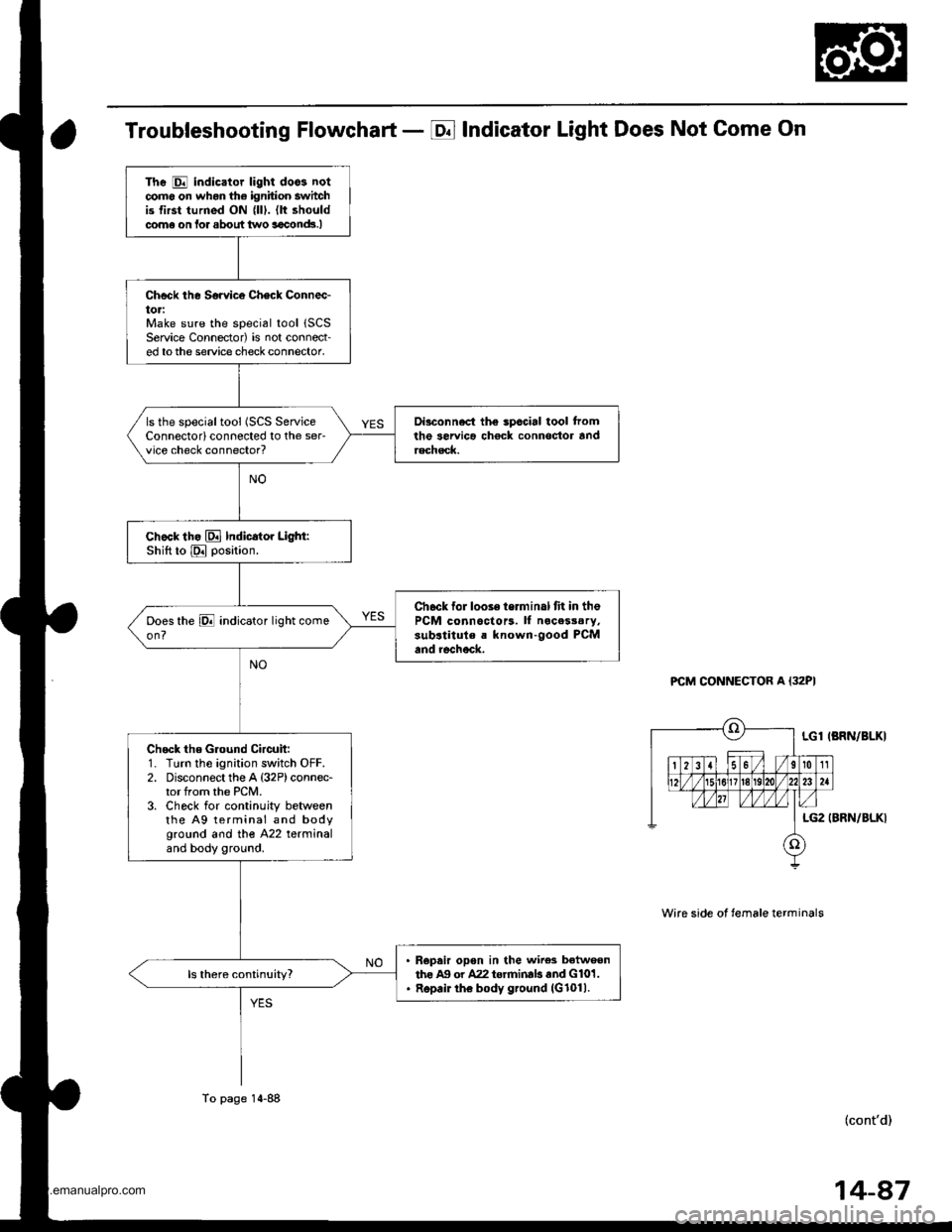
Troubleshooting Flowchart - E Indicator Light Does Not Come On
PCM CONNECTOR A {32PI
Wire side ot temale terminals
LGl IBRN/BLKI
LG2 (BRN/BLKI
(cont'd)
The E indicator light doos notcomo on whon the ignition switchis first turned ON {lll. (lt shouldcome on lor about two aaclnd!.I
Check the Sorvice Check Connec-toriMake sure the special tool 1SCSService Connector) is not connect-ed tothe service check connector,
Di3connect the spccial tool tromthe servica chock connoctor andrechsck.
ls the specialtool (SCS ServiceConnectorlconnected to the ser-vice check connector?
chock th. El Indicator Light:Shift to E position.
Ch6ck for looie terminal fit in thePCM connoctors. ll nocesssry,sub.titule a known-good PCMand rechock.
Check the Ground Circuit:1. Turn the ignition switch OFF.2. Disconnect the A {32P)connec-tor from the PCM.3. Check for continuity betweenthe A9 terminal and bodyground and tho A22 terminaland body ground.
R€pair opon in the wire3 betweenthe Ag or A22 torrninab and G101.Repair the body ground (G1011.
To page 14-88
14-87
www.emanualpro.com
Page 635 of 1395
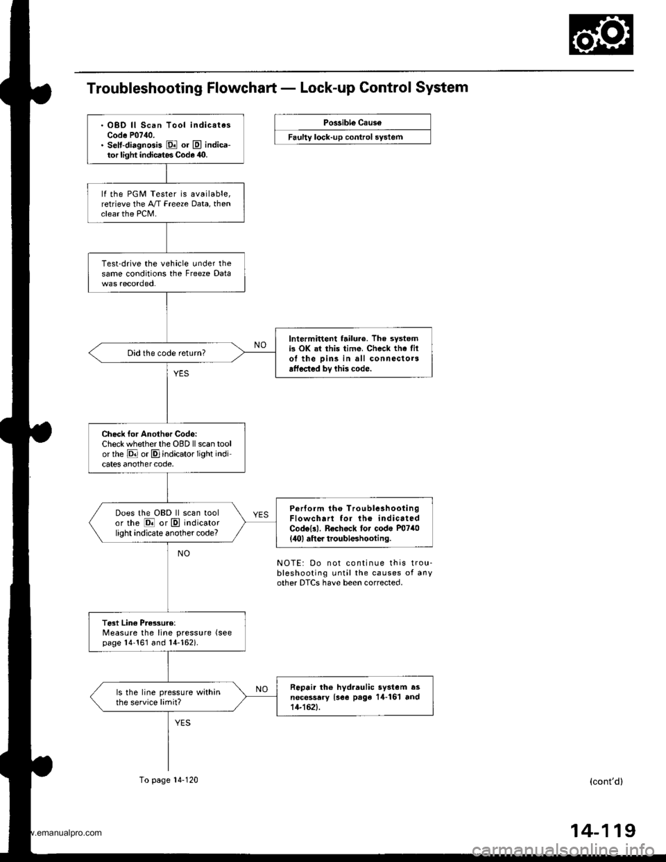
Troubleshooting Flowchart - Lock-up Control System
Possible Caus6
Faulty lock-up control system
. OBD ll Scan Tool indicatesCode P07,10.. selt-diagnGis El or E indica-tor light indicates Code 40.
lf the PGM Tester is available,retrieve the A/T Freeze Data, thenclear the PCM.
Test-drive the vehicle under thesame conditions the Freeze Data
lntermittent failur6. The systemis OK at this time, Check the filol the pins in all connectorsaffected bv lhis code.
Did the code return?
Check for Another Codc:Check whether the OBD ll scan toolor rhe E or E]indicator light indicates anothercode,
Perform tho TroubleshootingFlowchart for lh6 indicatedCodolll. Rechock tor code P0740(,lO) aft er troubleshooting.
Does the OBD ll scan toolor the @ or E indicatorlight indicate another code?
Test Lin€ Pres3uro:Measure the line pressure (see
page 14'161 and 14-162i.
Repair th6 hyd.aulic system asnecessary {see page 14-161 and14-152).
ls the line pressure withinthe service limit?
To page 14-120
NOTE: Do not continue this trou-bleshooting until the causes of anyother DTCS have been corrected.
(cont'd)
14-119
www.emanualpro.com
Page 637 of 1395
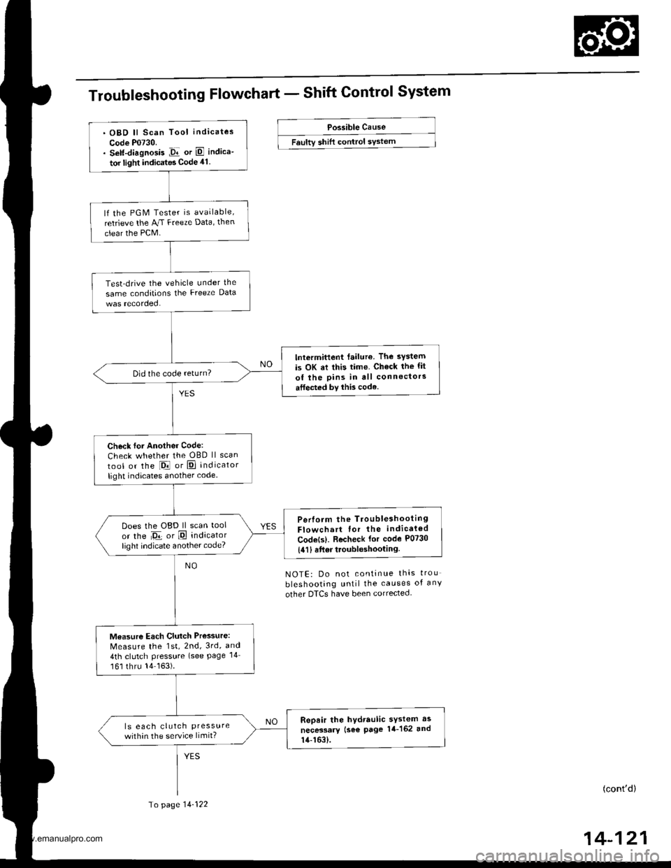
Troubleshooting Flowchart - Shift Control System
Possible Cause
Faultv shift control sYstem
NOTE: Do not continue thas trou
bleshooting until the causes of any
other DTCS have been corrected.
(cont'd)
14-121
. OBD ll Scan Tool indicates
Code P0730.. Self-diagnosis Jir or E indica-
tor light indicates Code 41.
lf the PGM Tester is available,
retrieve the AJ.I Freeze Data, then
clear the PCM.
Test-drive the vehicle under the
same conditions the Freeze Data
lntermittent failure. The system
is OK at this time. Ch€ck the fit
of the pins in all connectors
atfected by this code.
Did the code return?
Check for Another Code:
Check whether the OBD ll scan
tool or the l-Drl or E] indicator
light indicates another code.
Perlorm the TroubleshootingFlowchart for the indicaled
Codets). Recheck for code P0730
{411 6ft6r troubleshooting.
Does the OBD ll scan tool
or the Da or E indicatorlighl indicate another code?
Measure Each Clutch Pressure:
Measure the 1st, 2nd, 3rd, and
4th clutch Pressure (see Page 14
161 thru 14163).
Repair the hydraulic sYstem as
necessary (se€ page 14-162 and
14-163).
ls eac h clutch Pressurewithin the service limit?
To page 14-122
www.emanualpro.com
Page 639 of 1395
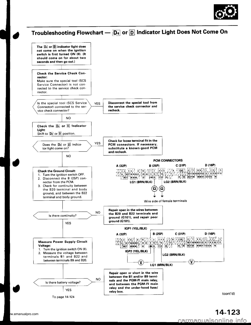
Troubleshooting Flowchart - Df or @ Indicator Light Does Not Come On
PCM CONNECTORS
B t2sPl c (31D (16P)
l*f4tr 8-
f - -- -6 3 rol ,: irr t lrpri$fe?0?r/a)1 e 'oI 13 11/ / l//|rrr I , ltelx ?r2? r,/i-T_LG1 {8RN/BI-KI I LG2 (BRN/BL()I
@@I++
Wire side of lemale terminals
(cont'd)
14-123
The E or El indicator light doe3not cofie on when the ignitaon
switch is first turned ON {ll). {ltshould como on for about two
s.cond3 and ihen go out.l
Check ths Service Check Con-
neclor:Make sure the special tool (SCS
Service Connector) is not connected to the service check connector.
Disconnecl the special lool lromtha service check connoctor andrecheck.
ls the special tool (SCS ServiceConnector) connected to the ser_vice check connector?
check the E or E Indicator
Ught:Shift to E or E position.
Check for loo3e t6lminal tit in thePCM connectors. lf necessary.substitute a known-good PCMand recheck.
Does the E or P indica-tor light come on?
Check the Gtound Circuil:1. Turn the ignition switch OFF.2. Disconnect the B (25P) con-nector from the PCM.3. Check for continuitY betweenthe 820 terminal and bodyground, and between the 822
terminal and body ground.
Repair open in the wires betweenthe 820 and 822 terminals andground {G1011, and r€Pair Poorground (G101).
ls there continuity?
Measure Power Supply CircuitVoltage:1. Turn the ignition switch ON 1ll).2. Measure the voltage betweenterminals B1 and 822 andbetween terminals Bg and 820.
Repair open or short in tho wi.ebetween the 81 and/or Bg tormi-nals and the PGM-FI main r€lay,.nd between tho PGM-FI mainrelay and the under-hood tuse/relay box.
ls there battery voltage?
A l32Plc (31P)
c (31P)
YES
To page 14-124
www.emanualpro.com
Page 660 of 1395
Interlock System
Interlock Control Unit Input Test
SRS components are located in this area. Review the SRS component locations, precautions, and procedures in the SRS
section (24) before performing repairs or service.
'1. Remove the instrument panel lower cover (see section 20).
2. Disconnect the 8P connector from the interlock control unit.
3. Inspect the connector and connector terminals to be sure they are all making good contact.
. lf the terminals are bent, loose, or corroded, repair them as necessary, and recheck the system
. lf the terminals look OK, make the following input tests at the connector.
- lf a test indicates a problem, find and correct the cause, then recheck the system
- lf all the input tests prove OK, substitute a known-good control unit, and recheck the system. lf the check is OK,
the control unit must be faulty; replace it.
NOTE: lf the shift lock solenoid clicks when the ign ition switch is tu rned ON (ll) while pressing the brake pedal withthe
shift lever in E position, the shift lock system is OK. lf the shift lever cannot be shifted from E position. test the A/T
gear position switch.
14-144
www.emanualpro.com
Page 662 of 1395
lnterlock System
Key Interlock Solenoid Test
SRS comoonents are located in this area. Review the SRS
component locations, precautions. and procedures in the
SRS section (24) before pertorming repairs or service.
1. Remove the instrument panel lower cover (see sec-
tion 20).
2. Disconnect the ignition switch 6P connector at the
connector holder.
6P CONNECTOR
14-146
3. Check for continuitv between the terminals in each
key position according to the table.
IGNITION SWITCH 6P CONNECTOR
Check that the key cannot be removed with power
connected to the No. 5 terminal and ground connected
to the No. 3 terminal.
lf the key cannot be removed. the key interiock
solenoid is OK.
lf the key can be removed, replace the steering
lock assembly (the key interlock solenoid is not
available separately).
\____________r{r4
Position
lgnition
switch
ACC 0)
Key pushed ino---'o
Key releasedo----o
www.emanualpro.com
Page 663 of 1395
Shift Lock Solenoid Test
SRS components are located in this area. Review the SRS
component locations, precautions, and procedures in the
SRS section (24) before performing repairs or service,
'1. Remove the instrument panel lower cover (see sec-
tion 20).
2. Remove the steering column covers (see section 17).
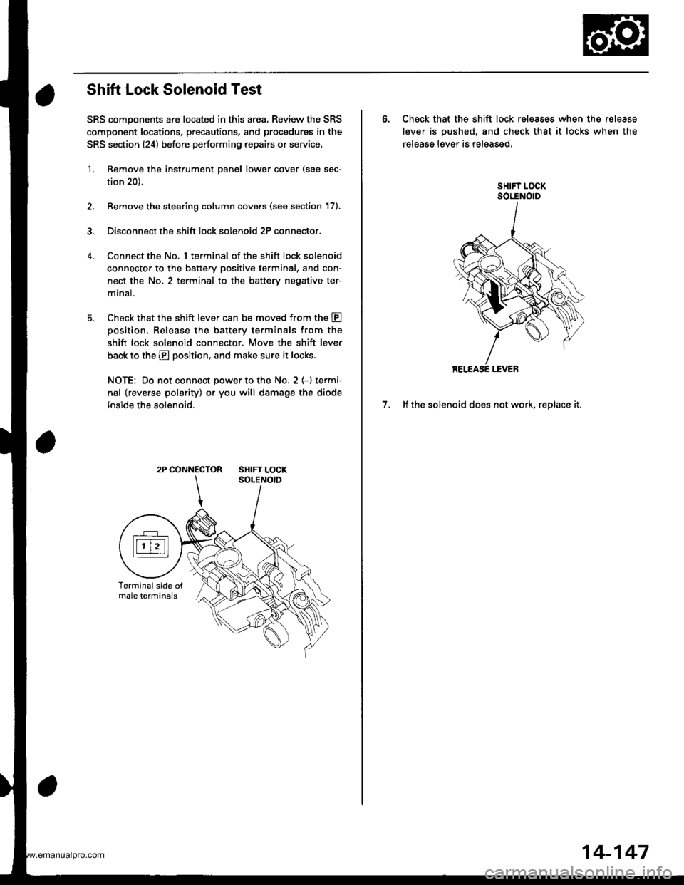
3. Disconnect the shift lock solenoid 2P connector.
Connect the No. 1 terminal of the shift lock solenoid
connector to the battery positive tgrminal, and con-
nect the No. 2 terminal to the battery nogative ter-
mrnal.
Check that the shift lever can be moved from the E
oosition. Release the batterv terminals from the
shift lock solenoid connector. Move the shift lever
back to the E position, and make sure it locks.
NOTE: Do not connect power to the No. 2 (-) termi-
nal {reverse polarity) or you will damage the diode
inside the solenoid.
2P CONNECTOR SHIFT LOCK
6. Check that the shift lock releases when the release
lever is pushed, and check that it locks when the
release lever is released,
7. lf the solenoid does not work, replace it.
14-147
www.emanualpro.com