Page 89 of 1395

Disconnest the lilP connector from the control unit.
Csvity WireTest condition
R€conn€ct tho 14P connGctor to the control unit.
Test: Desired resultPossible cause it result is not obtained
BRNAr'VHTUnder all conditionsCheck for resistance to groundl
There should be 80 - 120 o.
Faulty actuator solenoid
Poor ground (G202)
An open in the wire1BRNUnder all conditionsCheck for resistance to groundl
There should be 40 - 60 0.
11BRN/BLKUnder all conditionsCheck for resistance to ground:
There should be 70 - 110 O.
2GRY
lgnition switch ON (ll),
main switch ON and
brake pedal depressed,
then released
Check for voltage to ground:
There should be 0 V with the pedal
depressed and battery voltage with
the pedal released.
. Faulty brake switch. An open in the wire
BLKUnder all conditionsCheck for continuity to ground:
There should be continuity.
. Poor ground (G401). An open in the wire
5GRNMHT
Brake pedal depressed,
then released
Check for voltage to ground:
There should be battery voltage with
the pedal depressed, and 0 V with
the pedal released.
Blown No.52 1'15 Alfuse in the
under-hood fuse/relay box
Faulty brake switch
An open in the wire
LT GRN/
RED
Set button pushedCheck for voltage to ground:
There should be battery voltage.Blown No. 52 {'15 A} fuse in the
under-hood fuse/relay box
Faulty horn relay
Faulty sevresume switch
Faulty cable reel
An open in the wire7LT GRN/
BLK
Resume button pushed
10RED/BLU
lgnition switch ON lll)Attach to ground:
Cruise indicator light in the gauge
assembly should come on.
Elown bulbBlown No. 25 (7.5 A) tuse in theunder-dash fuse/relay box
Faulty dimming circuit in the gauge
assembly
An open in the wire
ELU^r'r'HT
lgnitjon switch ON {ll}and main switch ON;
raise the front of the
vehicle, block one wheel
and rotate the other
wheel slowly.
Check for voltage between the
ELUA/VHT @ and BLK O terminalsl
There should be 0 - 5 V or more-0 - 5 V or more repeatedly.
Faulty vehicle speed sensor (VSS)
An open in the wire
r3LT GRN
lgnition switch ON {ll}and main switch ONCheck for voltage to ground:
There should be battery voltage.
Blown No. 14 (7.5 A) fuse in theunder-dash fuse/relay box
Faulty main switch
An open in the wire
l4PNK
A'/T: Shift lever in E, EotE
lvl/T: Clutch pedal
releaseo
Check for continuity to ground:
There should be continuity.NOTE: There should be no continu-
ity when the shift lever is in otherpositions or when the clutch pedal is
oepresseo.
Faulty A/f gear position switch 1A,/TlFaulty or misadjusted clutch switch
fi{/r)Poor ground (G101)
An open in the wire
BLU
Start tho engine. turnthe main switch ON, anddrive the vehicle over 25
mph (40 km/h)with the
crurse control set
Check for voltage to ground:
There should be approx.5 V
. Faulty cruise control unit. Shod to ground
*: '98 - 00 models with Automatic Transmission.
4-39
www.emanualpro.com
Page 91 of 1395

n-
n-
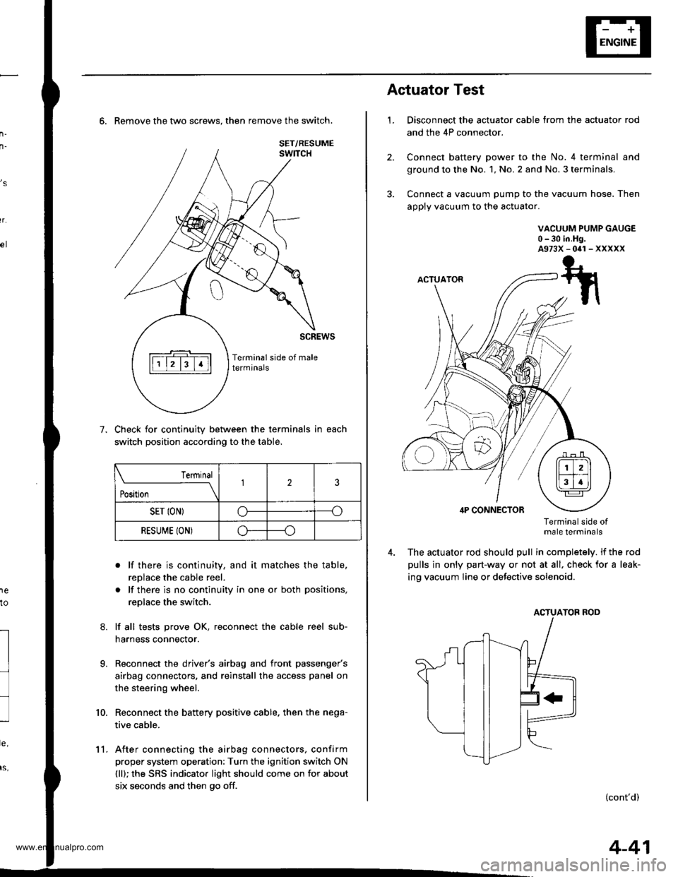
6. Remove the two screws. then remove the switch.
Check for continuity between the terminals in each
switch position according to the table.
. lf there is continuity, and it matches the table,
replace the cable reel.
. lf there is no continuity in one or both positions,
replace the switch.
lf all tests prove OK, reconnect the cable reel sub-
harness connector.
Reconnect the driver's airbag and front passenger's
airbag connectors, and reinstall the access panel on
the steering wheel.
Reconnect the battery positive cable. then the nega-
tive cable.
After connecting the airbag connectors, confirm
proper system operation: Turn the ignition switch ON
(ll); the SRS indicator light should come on for about
six seconds and then go off.
,s
r.
1e
to
7.
l
9.
10.
SET/RESUME
Terminal
t*,r*
-__\l23
SET ION)o----o
RESUME (ON)o----o
11.
4-41
1.
Actuator Test
Disconnect the actuator cable trom the actuator rod
and the 4P connector.
Connect battery power to the No. 4 terminal and
ground to the No. 1, No. 2 and No. 3 terminals,
Connect a vacuum pump to the vacuum hose. Then
apply vacuum to the actuator.
VACUUM PUMP GAUGE0-30 in.Hg.A973X-041-XXXXX
Terminalside otmale terminals
The actuator rod should pull in completely. lf the rod
pulls in only part-way or not at all, check for a leak-
ing vacuum Iine or defective solenoid.
ACTUATOB ROD
(cont'd)
www.emanualpro.com
Page 94 of 1395
Cruise Control
Brake Switch Test
1. Disconnect the 4P connector from the switch,
2. Remove the brake switch.
Terminal side of maletermtnals
Check for continuity between the terminals accord-
ing to the table.
lf necessary, replace the switch or adjust pedal height
(see section 19).
{P CONNECTOR
Terminal
;;;;-t
15
RELEASEDO----o
PUSHEDo--o
4-44
ACTUATOR
Actuator Solenoid Test
1. Disconnect the 4P connector from the actuator.
Terminalside ofmale terminals
Check for resistance between the terminals accord-
ing to the table.
NOTE: Resistance will vary slightly with tempera-
ture; specified resistance is at 68"F (20"C).
VALVE
I
I
I
To VACUUMTANK
Terminal
il',",""*(t)
_\13
VENT SOLENOID
40-600o--o
VACUUM SOLENOIDo---o
30-500
SAFEW SOLENOID
40-600o----o
VACUUM
www.emanualpro.com
Page 116 of 1395
Valve Clearance
Adiustment
Adjust the valves only when the cylinder head tempera-
ture is less than 100"F (38"C).
1. Remove the cylinder head cover.
Remove the middle cover (see page 6-11).
Set the No. 1 piston at TDC. The "UP" mark on the
pulleys should be at the top, and the TDC marks on
the pulleys should align with the pointers on the back
POINTERPOINTER
Adjust the valves on No. 1 cylinder.
Intake: 0.08 - 0.12 mm (0.003 - 0.005 inl
Exhaust: 0.16 - 0.20 mm (0.006 - 0.008 in)
Loosen the locknut, and turn the adiustment screw
until the feeler gauge slides back and forth with a
slight amount of drag.
LOCI(NUT9 x 0.75 m.n
Adiusting Screw Locations:
INTAKE
No.4 No.3 No.2
(cont'd)
6-3
25 N.m 12.5 kgf.m, 18lbf.ft)
EXHAUST
No. 1
www.emanualpro.com
Page 136 of 1395
Valves, Valve Springs
and Valve Seals
13. Measure the cam lobe height.
Cam Lobe Height Standard (Newl'97 - 98 models:
INTAKE: 33.20,1mm (1.3072 in)
EXHAUST: 33.528 mm (1.3200 inl'99 - 00 models:
INTAKE: 33.716 mm 11.327t1in)
EXHAUST:33.528 mm (1.3200 in)
Inspect this area lor wear.
Removal
ldentify the valves and valve springs as they are
removed so that each item can be reinstalled in its origi-
nal Dosition.
1. Using an appropriate-sized socket and plastic mallet.
lightly tap the valve retainer to loosen the valve keeP
ers before installing the valve spring compressor'
2. Install the spring compressor. Compress the spring
and remove the valve keeper.
VALVE SPRING COMPRESSORKD No. 3&!. whh *'5 JAW o.
VALVE SPRING COMPRESSORATTACHMEUT07757 - PJ1010A
(cont'd)
6-23
www.emanualpro.com
Page 141 of 1395

Valve Seats
Reconditioning
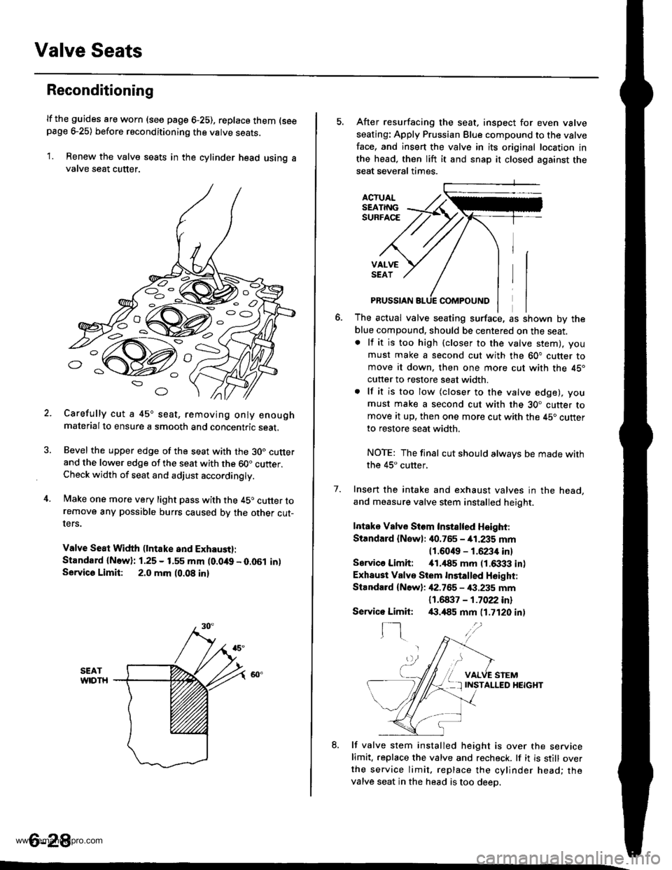
lf the guides are worn (see page 6-25), replace them (seepage e25) before reconditioning the valve seats.
1. Renew the valve seats in the cylinder head using avalve seat cutter.
Carefully cut a 45o seat, removing only enoughmaterialto ensure a smooth and concentric seat.
Bevel the upper edge of the seat with the 30. cutterand the lower edge of the seat with the 60" cutter.Check width of seat and adjust acco.dingly.
Make one more very light pass with the 45o cutter toremove any possible burrs caused bv the other cut-ters.
Valve Seat Width (lntake and Exhaust):
Standard {N.w}: 1.25 - 1.55 mm (0.049 - 0.051 in)Servica Limit: 2.0 mm (0.08 in)
o
o
5. After resurfacing the seat, inspect for even valve
seating: Apply Prussian Blue compound to the valve
face, and insert the valve in its original location in
the head, then lift it and snap it closed against the
seat several times.
ACTUALSEATINGSURFACE
VALVESEAT
7.
PRUSSIAN
The actual valve seating surface, as shown by the
blue compound, should be centered on the seat.. lf it is too high (closer to the valve stem), you
must make a second cut with the 60" cutter tomove it down, then one more cut with the 45"
cutter to restore seat width.
. lf it is too low (closer to the valve edge), you
must make a second cut with the 30. cutter tomove it up, then one more cut with the 45. cutter
to restore seat width.
NOTE: The final cut should alwavs be made withthe 45" cutter,
Insert the intake and exhaust valves in the head,
and measure valve stem installed heioht.
Intake Vslve Siem Instslted Height:
Standard {Newl: it0.765 - 41.235 mm
11.6049 - 1.6234 inl
Sarvico Limit: itl.il85 mm (1.6333 in)
Exhaust Valve Stem Installed H6ight:
Standard {New}: 42.755 - €.235 mm
11 .61137 - 1 .7022 inl/(|.,185 mm (1.7120 in)
VALVE STEMINSTALLED HEIGHT
8. lf valve stem installed height is over the servicelimit. replace the valve and recheck. lf it is still overthe service limit. replace the cylinder head; thevalve seat in the head is too deeo.
Servico Limit:
f-]
6-28
www.emanualpro.com
Page 142 of 1395

Valves, Valve Springs and Valve Seals
lnstallation
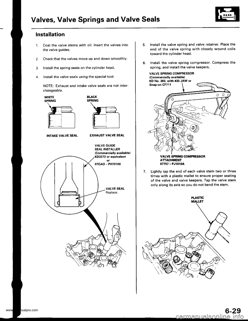
Coat the valve stems with oil. Insert the valves into
the valve guides.
Check that the valves move up and down smoothly.
Install the spring seats on the cylinder head.
Install the valve seals using the special tool.
NOTE: Exhaust and intake valve seals are not inter-
1.
changeable.
WHITESPRING
BLACKSPRING
INTAKE VALVE SEALEXHAUST VALVE SEAL
VALVE GUIDESEAL INSTALLER
lCommercially available)KO3372 or equival€ntot07GAD - PH70100
VALVE SPRING COMPRESSOR
lComm6rcially available)KD No. 383, with *35 JAw or
7.
Install the valve spring and valve retainer. Place the
end of the valve spring with closely wound coils
toward the cylinder head,
Install the valve spring compressor. Compress the
spring, and install the valve keepers.
VALVE SPRIT{G OOMPfi ESSORATTACHMENT0775' - PJ1010A
Lightly tap the end of each valve stem two or three
times with a plastic mallet to ensure proper seating
of the valve and valve keepers, Tap the valve stem
only along its axis so you do not bend the stem.
PLASTE
6-29
www.emanualpro.com
Page 146 of 1395

21.
22.
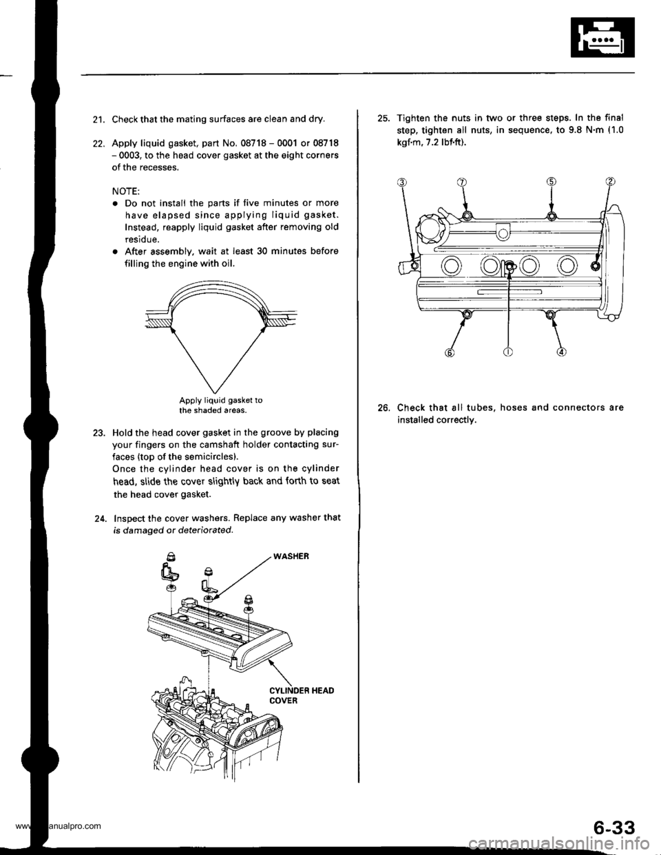
Check that the mating surfaces are clean and dry.
Apply liquid gasket, part No. 08718 - 0001 or 08718- 0003, to the head cover gasket at the eight corners
of the recesses.
NOTE:
. Do not install the parts if five minutes or more
have elapsed since applying liquid gasket.
Instead, reapply liquid gasket after removing old
residue.
. After assembly. wait at least 30 minutes before
filling the engine with oil.
Apply liquid gasket tothe shaded areas.
Hold the head cover gasket in the groove by placing
your fingers on the camshaft holder contacting sur-
faces (top of the semicirclesl.
Once the cylinder head cover is on the cylinder
head, slide the cover slightly back and forth to seat
the head cover gasket.
Inspect the cover washers. Replace any washer that
is damaged or dete(iorated.
23.
24.
25. Tighten the nuts in tvvo or three steps. In the final
step, tighten all nuts, in sequence. to 9.8 N.m (1.0
kgf.m, 7.2 lbf.ft).
Check that all tubes, hoses and connectors are
installed correctly.
26.
6-33
www.emanualpro.com