Page 474 of 1395
8. Install sth gear using the special tools and a press.
PRESS
I
DRIVER, 40 mm l.D.
07715 - 0030300
ATTACHMENT,30 mm LD.077,16 - 0030300
LInstall the needle bearing using the special tools
and a press, then installthe bearing outer race
PRESS
I
DRIVER. 40 mm l.D.077{6 - 0030100
ATTACHMENT,30 mm l.D.07746 - 0030300
NEEDLEBEASING
10. Install the ball bearing using the special tools and a
press.
PRESS
I
DRIVER. 40 mm LD.07746 - 0030100
ATTACHMENT,30 mm LD.077a6 - 0030300
11.Securely clamp the countershaft assembly in
bench vise with wood blocks.
LOCKNUTReplace.
Install the spring washer.
Install the new locknut to the correct torque, then
stake the locknut tab into the groove.
Torque: 127 + 0 + 127 N.m 113 - 0 +13 kgf.m,
94+0-94|bf.ft)
12.
wooD slocKs
13-35
www.emanualpro.com
Page 487 of 1395
Transfer Assembly
Disassembly (cont'd)
Secure the transfer housing in a bench vise withsoft jaws.
COMPANION FLANGEHOLDER07RAA -
Install the special tool on the companion flange,then loosen the transfer driven gear shaft locknut.
Remove the transfer driven gear shaft locknut, coni-cal spring washer, back-up ring, O-ring, and com-psnion flange.
7.
TRANSFER DRIVENGEAR SHAFT LOCKNUTReolace,
13-48
9. Remove the transfer driven gear shaft, then removethe transfer spacer from the transfer driven gearshaft.
TRANSFER ORIVENGEAR SHAFT
Remove the oil seal and the tapered roller bearingfrom the transfer housing,
OIL SEALReplace.
TAPEREO ROLIIRAEARING
TRANSFER HOUSING
www.emanualpro.com
Page 493 of 1395

Transfer Assembly
Reassembly (cont'd)
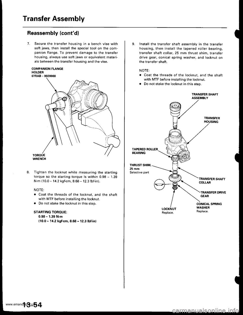
7.Secure the transfer housing in a bench vise with
soft jaws, then install the special tool on the com-
panion flange. To prevent damage to the transfer
housing, always use soft jaws or equivalent materi-
als between the transfer housing and the vise.
COMPANION FLANGEHOLDER07RAB - 0020000
WRENCH
8. Tighten the locknut while measuring the starting
torque so the starting torque is within 0.98 - 1.39
N.m {10.0 - 14.2 kgf.cm. 8.68 - 12.3 lbf.in).
NOTE:
. Coat the threads of the locknut, and the shaft
with MTF before installing the locknut.
. Do not stake the locknut in this step.
STARTING TOROUE:
0.98 - 1.39 N.m(10.0 - 14.2 kgf.cm, 8.68 - 12.3 lbf.in)
9.Install the transfer shaft assembly in the transfer
housing, then install the tapered roller bearing,
transfer shaft collar,25 mm thrust shim, transfer
drive gear, conical spring washer, and locknut on
the transfer shaft.
NOTE:
. Coat the threads of the locknut, and the shaft
with MTF before installing the locknut.
. Do not stake the locknut in this step.
TRANSFER SHAFTASSEMBLY
TRANSFER
THRUST SHIM.25 mmSelective part
COLLAR
TRANSFER DRIVEGEAR
CONICAL SPRINGWASHERReplace.Replace.
www.emanualpro.com
Page 496 of 1395

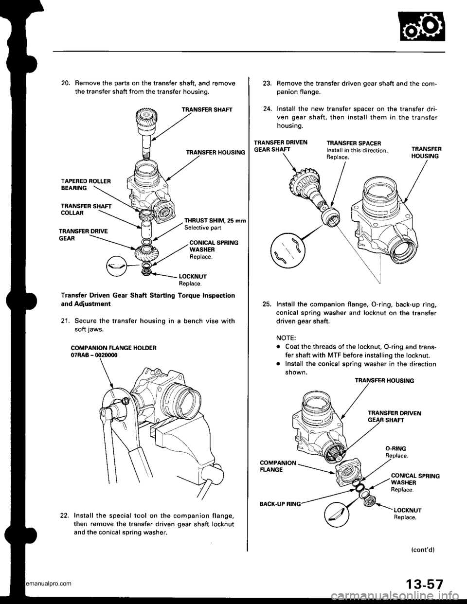
20. Remove the parts on the transfer shaft, and remove
the transfer shatt from the transfer housinq.
TRANSFER SHAFT
TRANSFER HOUSING
TAPERED ROLLERBEARING
TRANSFER SHAFTCOLLAR
TMNSFER DRIVEGEAR
THRUST SHIM, 25 mmSelective part
CONICAL SPRINGWASHERReplace.
LOCKNUTReplace.
Transter Driven Gear Shaft Starting Torque Inspection
and Adlustment
21. Secure the transfer housing in a bench vise with
soft iaws.
Install the special tool on the companion flang€,
then remove the transfer driven gear shaft locknut
and the conical spring washer.
COMPANION FLANGE HOLDER
22.
BACK.UP
Remove the transter driven gear shaft and the com-
panion flange.
Install the new transfer spacer on the transfer dri-
ven gear shaft, then install them in the transfer
housing.
TRANSFER DRIVENGEAR SHAFTTRANSFER SPACERInstall in this direction.TRANSFER
25.Install the companion flange, O-ring, back-up ring,
conical spring washer and locknut on the transfer
driven gear shaft.
NOTE:
. Coat the threads of the locknut, O-ring and trans-
fer shaft with MTF before installing the locknut.
. Install the conical spring washer in the direction
shown.
TRANSFER HOUSING
O.RING
COMPANIONFLANGECONICAL SPRINGWASHERReplace.
LOCKNUTReplace.
(cont'd)
13-57
www.emanualpro.com
Page 497 of 1395

Transfer Assembly
Reassembly (cont'dl
26. Secure the transfer housing in a bench vise with
soft jaws.
COMPANION FLANGE HOLDER07RAB - 002tD00
27. Install the special tool on the companion flange.
then tighten the transfer driven gear shaft locknut
while measuring the starting torque of the transfer
driven gear shaft.
STARTING TOROUE:
0.98 - 1.39 N.m
{10.0 - 1i1.2 kgf.cm, 8.68 - 12.3 lbf in}
TIGHTENING TOROUE:
132 - 216 N.m
(13.5 - 22.0 kgf.m, 97.6 - 159 lbf.ft)
NOTE:
. Rotate the companion flange several times to
seat the tapered roller bearing, then measure the
startrng torque.
. lf the starting torque exceeds 1.39 N.m (14.2
kgf.cm, 12.3 lbf.in), .eplace the transfer spacer
and reassemble the parts. Do not adjust the
torque with the locknut loose.
. lf the tightening torque exceeds 216 N.m (22.0
kgf.m, 159 lbf'ft), replace the transfer spacer and
reassemble the parts.
. Write down the measurement of the starting
torque: it is used to measure the total starting
torque.
28. Stake the locknut into the transfer driven oear shaft
using a 3.5 mm punch.
0.7 - 1.2 mm(0.03 - 0.05 inl
Point to bestaked.
Install the transfer shaft assemblv in the transfer
housing, then install the tapered roller bearing,
transfer shaft collar, 25 mm thrust shim, transfer
drive gear, conical spring washer, and transfer shaft
locknut on the transfer shaft.
NOTE:
. Coat the threads of the locknut and transfer shaft
with MTF before installing the locknut.
. lnstall the conical spring washer in the direction
snown.
TMNSFER SHAFTASSEMBLY
TRANSFER HOUSING
TAPERED ROLLERBEARING
TRANSFER SHAFTCOLLAR
TRANSFER DRIVEGEAR
PUNCH3.0-3.5 mm10.12 - 0.1a inl
THRUST SHIM, 25 mmSelective part
CONICAL SPRINGWASHEBReplace.
LOCKNUTReplace.
29.
www.emanualpro.com
Page 498 of 1395
30. Hold the transfer shaft with a 14 mm Allen wrench
clamDed in a bench vise.
NOTE: The locknut has left-hand threads.
TOROUE: 118 N.m (12.0 kgt'm,86.8 lbf'ft)
31. Stake the locknut on the transfer shaft using a 3.5
mm Dunch.
PUNCH3.0 - 3.5 mm{0.12 - 0.14 inl
14 mm ALLEN WRENCH
Totsl Starting Torquo Inspoction and Adiustment
32. Temoorarilv install transfer cover A without the O-
ring.
TRANSFER HOUSING
TRANSFER COVER A
oEl
€lE/Ehvc/E\\g8 x 1 .25 mm24 N.m (2.4 kg{ m, 17 lbtftl
5t.Secure the transfer housing in a bench vise with
soft jaws. then rotate the companion flange several
times to fit the tapered roller bearing,
TOROUE WR€NCH
34. Measure the total starting torque.
TOTAL STARNNG TOROUE:
1.70 - 2.08 N.m 117.3 - 21.2 kgf.cm, 15.0 - 18.i1 lbf inl
+ Transter Driven Gear Shaft Starting Torque Value
(wrot€ down in step 27).
(cont'd)
13-59
www.emanualpro.com
Page 508 of 1395

12. Apply liquid gasket to the surface of the transmis-
sion housing as shown.
Note these items:
. Use liquid gasket (P/N 08718 - 0001 or 08718 -
0003).
. Remove the dirty fluid from the sealing surface.
. Seal the entire circumterence of the bolt holes to
prevent fluid leakage.
. lf 20 minutes have passed after applying liquid
gasket, reapply it and assemble the housings.
a Allow it to cure at least 20 minutes after assem-
bly betore filling the transmission with MTF.
Install the 14 x 20 mm dowel pins.
Set the stopper ring as shown. Place the transmis-
sion housing over the clutch housing, being careful
to line up the shafts. Be sure to align the stop ring
with the 5th shift fork finger tip.
r3.
14.
TRANSMISSION HOUSING
SHIFT FORK
vk..*,
Align point
17.
the 32 mm sealing bolt.
15. Lower the transmission housing with the snap ring
pliers. and set the snap ring into the groove of the
countershaft bearing.
Check that the snap ring is securely seated in the
groove of the countershaft bearing.
Dimension A as installod: 3.6 - 6.3 mm
(0.142 - 0.2/8 in)
16.
32 mm SEALING BOLT25 N m 12.5 kgf.m, 18 lbf.ftlSNAP RING
(cont'd)
13-69
Apply liquid gasket (P/N 08718 - 0001 or 08718 -
0003) to the 32 mm sealing bolt threads, then install
SNAP RING PLIERS
DOWEL PINS
www.emanualpro.com
Page 651 of 1395

Lock-up Control Solenoid Valve A/B Assembly
Test
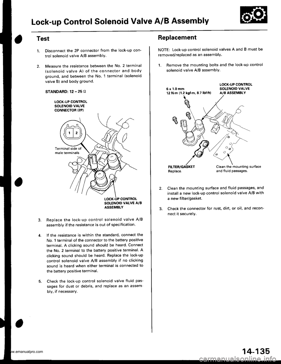
1.
2.
Disconnect the 2P connector from the lock-up con'
trol solenoid valve A'lB assembly.
Measure the resistance between the No. 2 terminal
(solenoid valve A) of the connector and body
ground. and bet\iveen the No. 1 terminal (solenoid
valve B) and body ground.
STANDARD: 12 - 25 o
LOCK-UP CONTROLSOLENOID VALVECONNECTOR I2P)
Replace the lock-up control solenoid valve A/B
assembly if the resistance is out of specification
lf the resistance is within the standard, connect the
No. 1 terminal of the connector to the battery positive
terminal. A clicking sound should be heard Connect
the No. 2 terminal to the battery positive terminal. A
clicking sound should be heard. Replace the lock-up
control solenoid valve Ay'B assembly if no clicking
sound is heard when either terminal is connected to
the banerv Dositive terminal.
Check the lock-up control solenoid valve fluid pas-
sages for dust or debris, and replace as an assem
bly, if necessary.
Terminalside ofmale terminals
LOCK.UP CONTROL
Replacement
NOTE: Lock-up control solenoid valves A and B must be
removed/replaced as an assembly.
1. Remove the mounting bolts and the lock-up control
solenoid valve A,,/B assembly.
LOCK.UP CONTROL6 x 1.0 mm SOLENOIO VALVE12 N.m 11.2 kgf.m,8.7 lbf.ft) A/B ASSEMBLY
Replace.Clean the mounting surfaceand flu id passages.
2.Clean the mounting surface and fluid passages, and
install a new lock-up control solenoid valve IVB with
a new filter/gasket.
Check the connector for rust, dirt, or oi!, and recon-
nect it securely.
oa
14-135
www.emanualpro.com