1998 HONDA CR-V Jack
[x] Cancel search: JackPage 807 of 1395
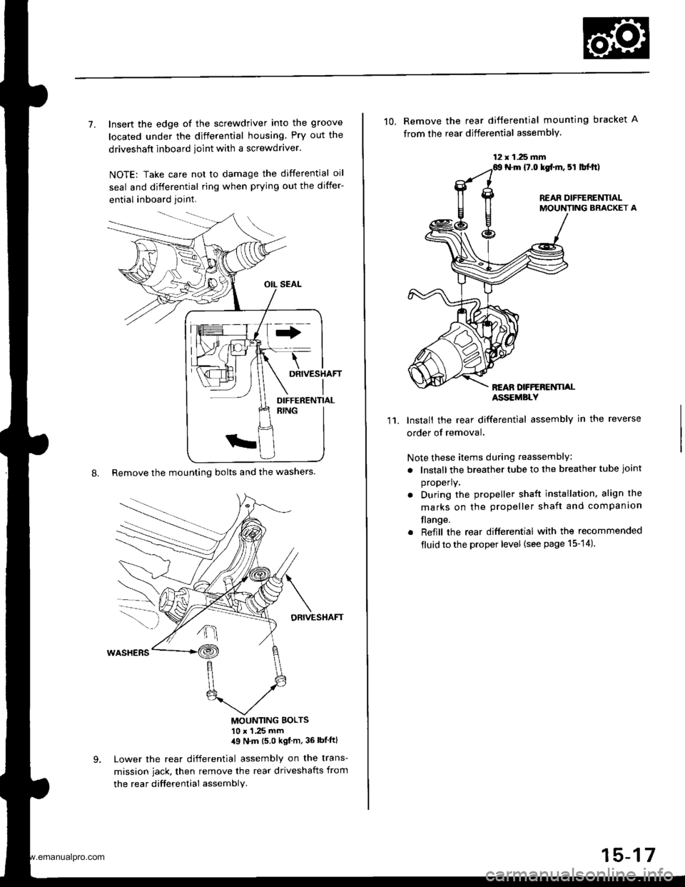
7. Insert the edge of the screwdriver into the groove
located under the differential housing Pry out the
driveshaft inboard ioint with a screwdraver.
NOTE: Take care not to damage the differential oil
seal and differential ring when prying out the differ-
ential inboard joint.
8. Remove the mounting bolts and the washers.
DRIVESHAFT
MOUNTING BOLTS'10 x 1 .25 mm,19 N'm (5 0 kgf m, 36 lbtftl
Lower the rear differential assembly on the trans-
mission jack, then remove the rear driveshafts from
the rea r difterential assembly.
DIFFERENTIAL
12 x 1.25 fifi
10. Remove the rear difterential mounting bracket A
from the rear differential assembly.
N.m {7.0 lgf.m. 5l lbl.tt)
REAR DIFFERENTIALMOUNTING BRACKET A
REAN DFFERENTI,ALASSEMBLY
11.Install the rear differential assembly in the reverse
order of removal.
Note these items during reassembly
. lnstall the breather tube to the breather tube joint
properly.
. During the propeller shaft installation, align the
marks on the propeller shaft and companion
flange.
. Reiill the rear differential with the recommended
fluid to the proper level {see page 15-14).
15-17
www.emanualpro.com
Page 876 of 1395
Power Steering Gearbox
Removal
Note these items during removal:
. Using solvent and a brush, wash any oil and dirt off
the valve body unit its lines, and the end if the gear-
box. Blow dry with compressed air.
. Be sure to remove the steering wheel before discon-
necting the steering joint. Damage to the cable reel
can occur.
. With 4WD. tilt the engine with a jack to expand the
clearance between the transfer assembly and rear
beam when removing the steering gearbox from the
rear oeam.
Do not remove the steering gearbox by removing the
transfer assembly from the transmission.
1. Drain the power steering fluid as described on page'17-15.
Raise the vehicle, and suppon it on safety stands in
the proper locations (see section 1).
Remove the front wheels,
Remove the drive/s airbag assembly {see section 24).
Remove the steering wheel {see page 17-18).
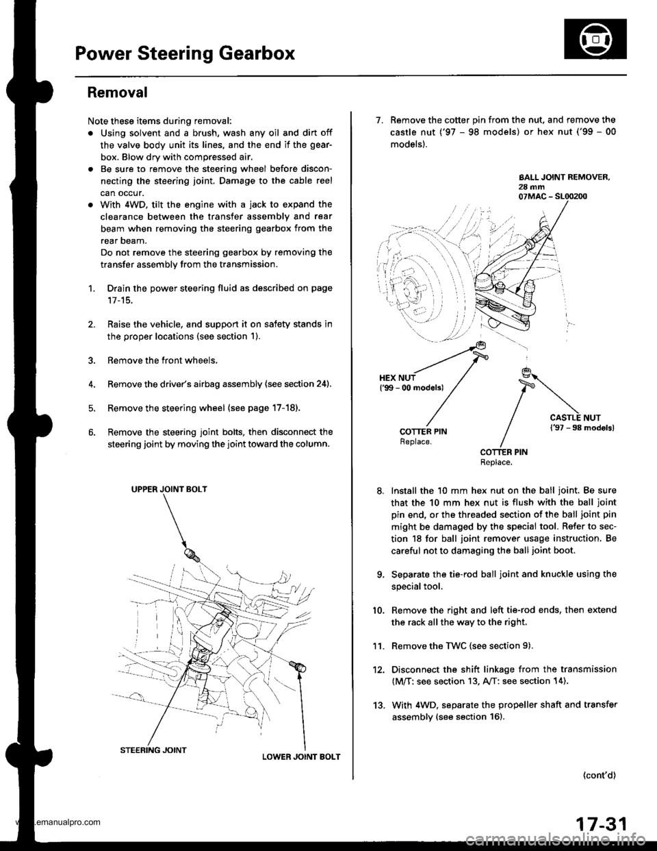
Remove the steering joint bolts, then disconnect the
steering joint by moving the joint toward the column.
UPPER JOINT BOLT
LOWER JOINT BOLT
13.
7. Remove the cotter pin from the nut, and remove the
castle nut {'97 - 98 models) or hex nut ('99 - 00
models).
COTTER PINReplace.
Install the 10 mm hex nut on the ball joint. Be sure
that the 10 mm hex nut is flush with the ball joint
pin end, or the threaded section of the ball joint pin
might be damaged by the special tool. Refer to sec-
tion 18 for ball joint remover usage instruction, Be
careful not to damaging the ball joint boot.
Separate the tie-rod ball joint and knuckle using the
special tool.
Remove the right and left tie-rod ends, then extend
the rack all the way to the right.
Remove the TWC (see section 9).
Disconnect the shift linkage from the transmission
(M/T: see section 13, A/T: see section 14).
With 4WD. separate the propeller shaft and transfer
assembly (see section 161.
10.
11.
(cont'd)
17-31
www.emanualpro.com
Page 878 of 1395
REAR MOUNT
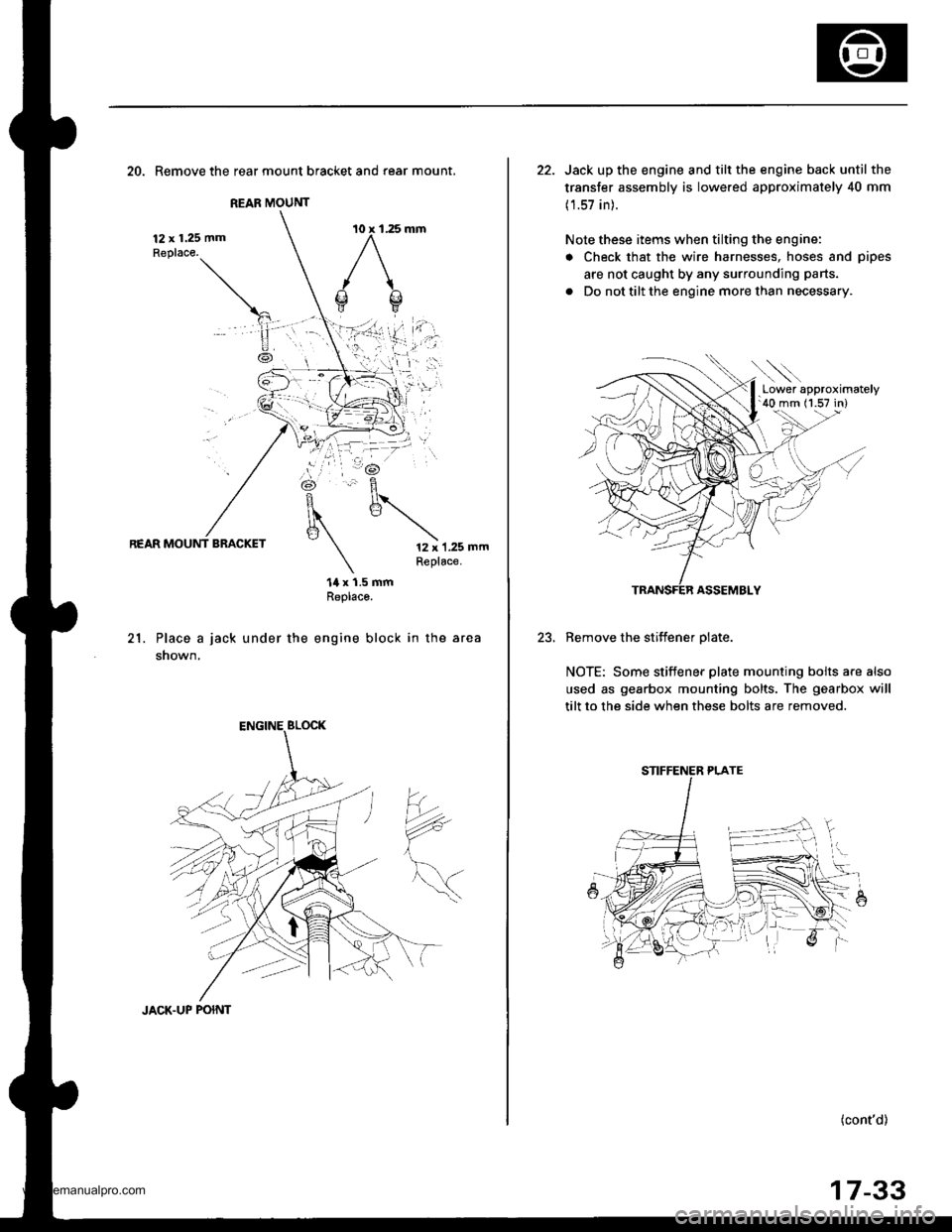
20. Remove the rear mount bracket and rear mount.
12 x 1.25 mmReplace.
REAR MOUNT BRACKET12 x 1.25 mmReplace.
21.
14 x 1.5 mmReplaco.
Place a jack under the engine block in the area
shown,
?*
JACK.UP POINT
17-33
22. Jack up the engine and tilt the engine back until the
transfer assembly is lowered approximately 40 mm
(1.57 in).
Note these items when tilting the engine:
. Check that the wire harnesses, hoses and pipes
are not caught by any surrounding parts.
. Do not tilt the engine more than necessary.
ASSEMBLY
Remove the stiffener olate.
NOTE: Some stiffener plate mounting bolts a.e also
used as gearbox mounting bolts. The gearbox will
tilt to the side when these bolts are removed.
(cont'd)
.Lower approximately'40 mm (1.57 in)
STIFFENER PLATE
www.emanualpro.com
Page 923 of 1395
Reassembly
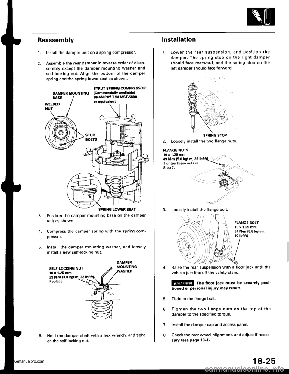
1.Install the damper unit on a spring compressor,
Assemble the rear damper in reverse order of disas-
sembly except the damper mounting washer and
self-locking nut. Align the bottom of the damper
spring and the spring lower seat as shown.
2.
DAMPER MOUNNNG
STRUT SPBING COMPRESSOR:(Commorcislly !v.ilablelBRANICKC T/N MST.s8OA
3.Position the damper mounting base on the damper
unit as shown.
Compress the damper spring with the spring com-
pressor.
Install the damper mounting washer, and loosely
install a new self-locking nut.
SELF.LOCKING NUT10 x 1.25 mm29 N.m (3.0
Replace.
Hold the damper shaft with a hex wrench, and tight-
en the self-locking nut.
1.
lnstallation
Lower the rear suspenston,
damper. The spring stop on
should face rearward, and the
left damper should face forward.
and position the
the right damper
sprang stop on the
SPRING STOP
2. Loosely install the two flange nuts.
FLANGE NUTS10 x 1.25 mm . .:{9 N.m 15.0 kgf.m, 36 lbtft}- :',,-rigf't"n if'"""_nrr. in ----.-*
qla^ 7Step 7.
3. Loosely install the flange bolt.
FLANGE EOLT10 x 1.25 mm54 N.m 15.5 kgt.m,40 tbI.ft)
6.
7.
8.
Raise the rear suspension with a floor jack until the
vehicle just lifts off the safety stand.
@ The floor iack must be securely posi-
iioned or personal iniury may result.
Tighten the flange bolt.
Tighten the two flange nuts on the top of the
damper to the specified torque.
Install the damper cap and access panel.
Check the rear wheel alignment. and adjust if neces-
sary (see page 18-4).
18-25
www.emanualpro.com
Page 1347 of 1395
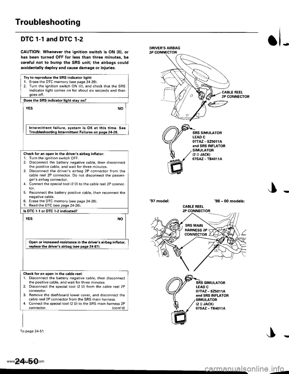
Troubleshooting
DTC 1-1 and DTC 1-2
CAUTION: Whenever the ignition switch is ON {ll}, or
has been turned OFF for less than three minutes, be
careful not to bump the SRS unit; the airbags could
accidentally deploy and cause damage o1 iniuries.
JDRIVEF'S AIRBAG2P CONNECTOR
CABLE REEL2P CONNECTOR
SRS SIMULATORLEAD C07TAZ - SZ5011Aand SRS INFLATORSIMULATORt2 0 JACKI07saz - TB40r1A
'97 modol:'98 - 00 models:
CABLE REEL2P CONNECTOR
SRS SIMULATORLEAD C07TAZ - SZ5011Aand SRS INFLATORSIMULATOR12 0 JACKI07sAz - TB4011A
J
24-50
Try to reproduce the SRS indicator light:1. Erase the DTC memory (see page 24-28).2. Turn the ignition switch ON (ll), and check that the SRSindicator light comes on tor about six seconds and thenooes off.
Does the SRS indicator liqht stav on?
YESNO
Intermiltent failure, svstem is OK at this time. SeeTrouble3hooting Intermittent Failures on page 24-28.
Check tor an open in the driver's airbag inflatori1. Turn the ignition switch OFF-2. Disconnect the battery negative cable, then disconnectthe positive cable, and wait for three minutes.3. Disconnect the driver's airbag 2P connector from thecable reel 2P connector- Do not disconnect the passenger's airbag connector.4. Connect the specialtool (2 O) to the cable reel 2P connector.5. Reconnect the batterv positive cable, then reconnect thenegative cable,6. Erase the DTC memory (see page 24-28).7. Read the DTC {see page 24-261.
ls DTC 1-1 or DTC 1-2 indicsted?
NOYES
Open or increased resistance in the driver's airbag inflato.;replacethe d.ive.'s airbag (s6e page 24-871.
Check foi an ooen in the cable reel:1. Disconnect the battery negative cable, then disconnectthe positive cable, and waat for three minutes.2. Disconnect the special tool (2 Oi from the cable reel 2P
3. Remove the dashboard lower cover, and disconnect thecable reel 2P connector from the SRS main harness.4. Connect the special tool (2 0) to the SBS main harness 2Pconnector, (cont'd)
To page 24'51
SRS MAINHARNESS 2PCONNECTOR
--
www.emanualpro.com
Page 1349 of 1395
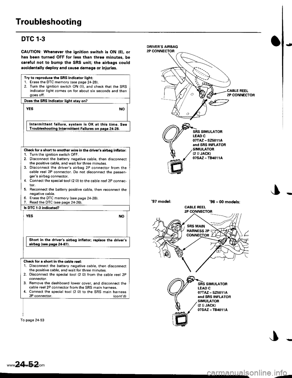
Troubleshooting
DTC 1-3
CAUTION: Whonovor the ignition switch is ON (ll), or
has been turnod OFF for less thsn three minutss. be
caroful not to bump the SRS unit; tha ailbags could
accidentally doploy and cau3o damage or iniuries.
J
ffi
SRS SIMULATORtfAD c0?TAZ - SZ5olrAand SRS INFLATOR
/SIMULATOR/ Q a JACKI
/' 07s,A-TB411A
,98 - 00 models:
CABLE REEL2P CONNECTOR
'97 model:
SRS SIMULATORLEAD C07TAZ - SZ50114and SnS INFLATORSIMULATOR{2 0 JACK}07sAz - TB{011A
Try to r.produce the SRS indicator light:1. Erase the DTC memory (see page 24-28).2. Turn the ignition switch ON (ll), and check that the SRSindicator light comes on for about six saconds and thengoes off.
Do.s the SRS indic.tor light stay on?
NOYES
Intermittenl failuro. sy3tom i3 OK at this time. SooTrouble3hooting Intormittenl Failure3 on prqo 24-28.
Chock for a short to enother wirG in the driver's sirbag inf,artor:1. Tlrn tho ignition switch OFF.2. Disconnect the battery negative cable, then disconnectthe positive cable, and wait for three minutes.3. Disconn€ct the driver's airbag 2P connector from thecablo re€l 2P connector, Do not disconnect the oassen-ger's airbag conn€ctor.4. Connect the specialtool (2 Olto the cable reel 2P connec-tor.5. Reconnect the baftery positive cable, then reconnect thenegative cable.6. Erase the DTC memory (see page 24-28).7. Read the DTC (see page 24-261.
b DTC 1-3 indicatod?
YESNO
Sho.t in the driv6r's airb.g intletor; replace the d v€r's.irb.g l3oo pag6 24€7).
Ch6ck lor a short in the cablc reol:'1. Disconnect the battery negative cable, then disconnectthe positive cable, and wait for three minutes.2. Disconnect the special tool {2 O) lrom the cable reel 2Pconneclor.3. Remove the dashboard lower cover, and disconnect thecable reel 2P connector from the SRS main harness.4. Connect the special tool (2 O) to the SRS main harness2P connector. {cont'd}
To pago 24-53
24-52
2P CONNECTOR
--
www.emanualpro.com
Page 1351 of 1395
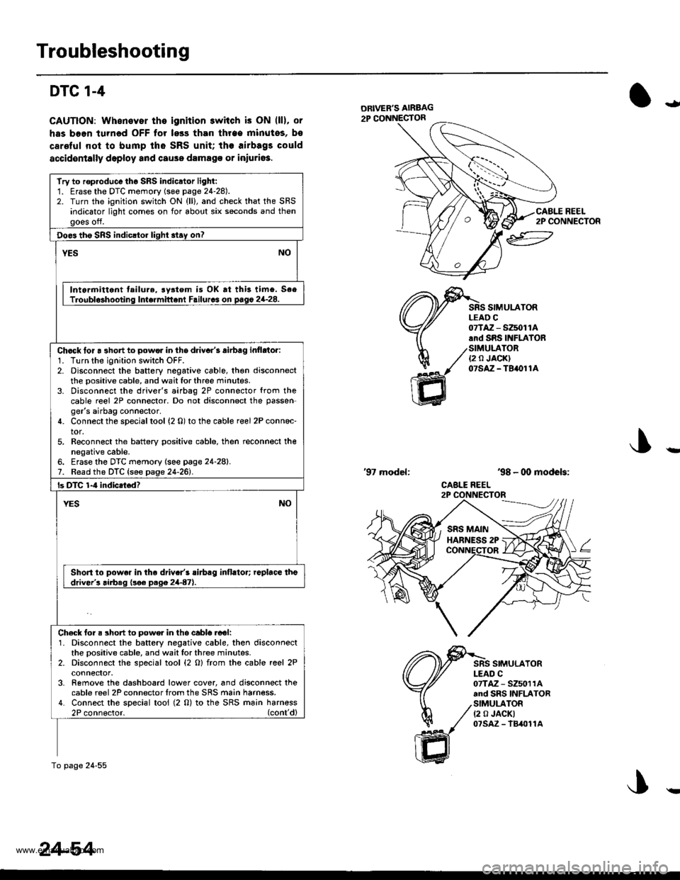
Troubleshooting
DTC 1-4
CAUTION: Whonover the ignition switch is ON (ll), or
has boen turned OFF for less than throe minutos, bs
carelul nol to bump tho SRS unit; the airbags could
accidentally deploy and cause damago or iniuri63.
ial
ltl
REEL2P CONNECTOR
SIMULATORLEAD C
ffi
07TAZ - SZ5011A.rd SRS INFIATOR
/SIMULATOR./ ea JA0KI
1( otstz-terore
'98 - 00 models:
CABLE REEL
'97 model:
SIMULATORI-EAD C07TAZ - SZ5011Aand SRS INFLATORSIMULATOR(2 0 JACKT07sAz - lB4011A
Try to rop.oduco tho SRS indicator light:1. Erase the DTC momory (soe page 24-28).2. Turn the ignition switch ON {ll}, and check that the SRSindicator light comes on for about six seconds and thengoes off.
Doe3 th6 SRS indicltor light 3tay on?
YESNO
Intormittent tailure, rystem is OK rt this timo. SeeTroubl$hooting Intermittent Failurcs on pago 2G28.
Chack lor a 3hort to powor in ths driyar's airbag inflrtor:1. Turn the ignition swilch OFF.2. Disconnect the battery negative cable, th€n disconnectthe positive cable, and wait for three minutes.3. Disconnect the driver's airbag 2P connector {rom thecable reel 2P connector. Do not disconnect the passen-ger's airbag connector.4. Connect the special tool (2 0) to the cable reel 2P conn6c-tor,5. Reconn€ct the battery positive cable. then reconnect thenegative cable.6. Erase the DTC memory (see page 24-28).7. Read the DTC {see page 24-261.
ls DTC 1-4 indicatod?
NOYES
Short to powe. in the driv.r's rirbrg inflator; replace theddver's airbeq (!o€ D.qa 2447).
Ch€ck for. short to powe. in tho cabl6.ool:1. Disconnect the battery negative cable, then disconnectthe oositive cable, and wait lor three minutes.2. Disconnect the special tool (2 O) from the cable reel 2Pconnefior,3- Remove the dashboard lower cover, and disconnect thecable reel 2P connector lrom the SRS main harness.4. Connect the special tool (2 0) to the SRS ma;n harn€ss2P connoctor. (cont'dl
To page 24-55
24-54
!
www.emanualpro.com
Page 1353 of 1395
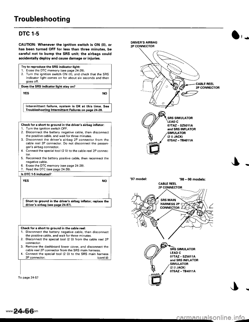
Troubleshooting
DTC l-s
CAUTION: Whenever tho igniiion switch is ON {ll), or
has been lurned OFF for loss lhan thrse minules, be
caretul not to bump the SRS unit; the airbags could
accidentally deploy and cause damage or iniuries.
O'-
DRIVER'S AIRBAG2P CONNECTOR
'97 model:
SRS SIMULATORLEAD C07TAZ - SZ50r1A.nd SRS INFLATORSIMULATOR{2 0 JACK)07sAz - TBaolrA
SRS SIMULATORLEAO C07TAZ - SZ5011Aand SRS INFLATORSIMULATORt2 0 JACKI07sAz - TB{01rA
ar
h/
ffi
'98 - 0O models:
CABLE REEL2P CONNECTOR
Try to reproduce the SRS indicator light:1. Erase the DTC memory (see page 24-28).2. Turn the ignition switch ON lll), and check that the SRSindicator light comes on for about six seconds and thengoes off.
Doos tho SRS indicator liqht stav on?
YESNO
Inte.mittent tailure,3y3tem is OK at this timo. 506Troubleshooling Intermittent Failures on Daq€ 24-28.
Check tor a short to ground in the driver's ai.bag intlator:1. Turn the ignition switch OFF.2. Disconnect the battery negative cable, then disconnectthe positive cable, and wa:l for three minutes.3. Disconnect the driver's airbag 2P connector from thecable reel 2P connector, Do not disconnect the passen,ger's airbag connector.4. Connect the special tool {2 O} to the cable reel 2P connec-tor.5. Reconnect the battery positive cable. then reconnect thenegative cable.6. Erase the DTC memory (see page 24 28).7. Read the DTC lsee page 24-261.
ls DTC 1-5 indicated?
YESNO
Short to ground in the driver's airbag inflator; replace thedriver's airbag (s6e page 24-871.
Chock for a short to ground in the cablo reel:1. Disconnect the battery negative cable, then disconnectthe positive cable, and wait for three minutes.2. Disconnect the special tool i2 O) from the cable reel 2P
3. Remove the dashboard lower cover, and disconnect thecable reel 2P connector from the SRS main harness.4. Connect the special tool {2 O) to the SRS main harness2P connector. (cont'd)
To page 24-57
24-56
CAALE REEL2P CONNECTOR
J..
.J
www.emanualpro.com