Page 1315 of 1395
Circuit Diagram
UNDER.DASHFUSE/RELAYBOX
NOTE: The SRS main harness uses all GRY('97 model) or GRN ('98 - 00 models) wires.
WHT/BLK -'- WHT
DRIVEB'SAIRBAGNFLATOR
A
#+
tt tll./ d I
GRY GRY(GRN) (GRN)
FRONTPASSENGER'SALRBAGINFLAlOR
tlGRY GFY(GFN) (GRN)
DRIVER'SSEAT EELTTENSIONER
FRONTPASSENGERSSEAT BELTTENSIONEF
GRN(BLU/PNK)
BLK
G401
24-18
PCM/ECM SERVICE MEMORY ERASECHECK S GNAL (MES)CONNECTOB CONNECTOR(2P)
DATA LINXCONNECTOR(Drc) (r6P)
Models)('98 - 00
IGNITION SWITCHUNDEF,HOOD FUSE/RELAY BOX
YEUGRN
+
PGM FImam relay
SFS INDICATOR CIRCUIT(ln lhe gauge assembly)
Shill loc* so enoid
BLU
GR\
GNY GRY
H
GFY GRYlcFNt (GlN)
??
I r-?LT BLU BRN BRN
tttr?F?F
VVV
SRS NDICATORL GHT {r.4W)
5 12 4 11 | 16 17 15 I 18 I
10 14 113
U
S8S UN T TERMINALS
3567I
101114151718
Terminal side of male terminals
-4
www.emanualpro.com
Page 1320 of 1395
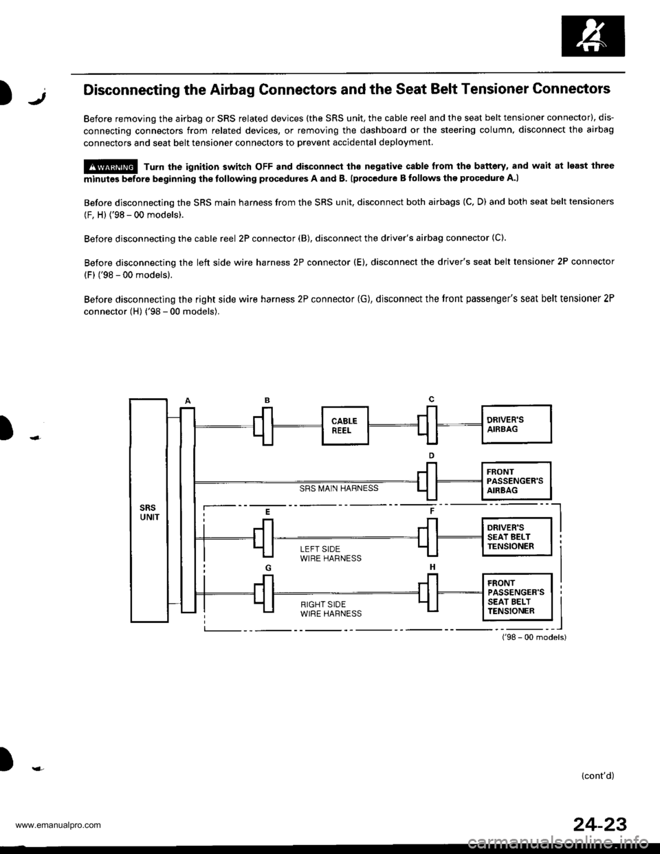
)1,Disconnecting the Airbag Gonnectors and the Seat Belt Tensioner Connectors
Before removing the airbag or SRS related devices (the SRS unit, the cable reel and the seat belt tensioner connector), dis-
connecting connectors from related devices, or removing the dashboard or the steering column, disconnect the airbag
connectors and seat belt tensioner connectors to Drevent accidental deployment
@ Turn the ignition switch oFF and disconnect ths nogative cable from the battery, and wait at least ihree
minutes before beginning the tollowing procedures A and B. lprocedure B follows the procedure A.l
Before disconnecting the SRS main harness from the SRS unit, disconnect both airbags (C, D) and both seat belt tensioners
(F, H) {'98 - 00 models).
Before disconnecting the cable reel 2P connector (B), disconnect the driver's airbag connector (C).
Before disconnecting the left side wire harness 2P connector (E). disconnect the driver's seat belt tensioner 2P connector
(F) ('98 - 00 models).
Before disconnecting the right side wire harness 2P connector (G), disconnect the tront passenger's seat belt tensioner 2P
connector (H) ('98 - 00 models).
SRS MA1N HARNESS
)
i--- E t ----l
i Jl Jl l*",r* I I
LEFT SIDEWIRE HARNESS
){cont'd)
24-23
www.emanualpro.com
Page 1321 of 1395
Precautions/Procedures
Disconneeting the Airbag Connectors and the Seat Belt Tensioner
Connectors (cont'd)
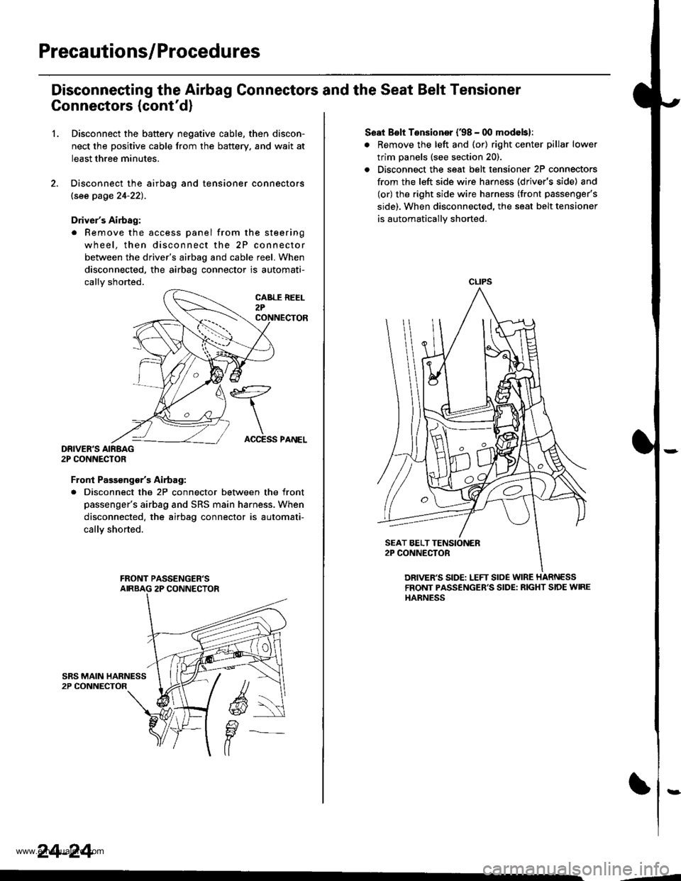
1.Disconnect the battery negative cable, then discon-
nect the positive cable from the battery. and wait at
least three minutes.
Disconnect the airbag and tensioner connectors
lsee page 24-22).
Driver's Airbag:
. Remove the access panel from the steering
wheel, then disconnect the 2P connector
between the driver's airbag and cable reel. When
disconnected, the airbag connector is automati-
callv shorted.
DRIVER'S AIRBAG2P CONNECTOR
Front Passsng€/sAirtag:
. Disconnect the 2P connector between the front
passenger's airbag and SRS main harness. When
disconnected. the airbag connector is automati-
callY shorted.
24-24
ACCESS PANEL
Seat Bslt Tensioner (38 - 00 modebl:
. Remove the left and (or) right center pillar lower
trim panels (see section 20).
. Disconnect the seat belt tensioner 2P connectors
from the left side wire harness (driver's side) and
(or) the right side wire harness (front passenger's
side). When disconnected. the seat belt tensioner
is automatically shorted.
CLIPS
DRIVER'S SIDE: LEFT SloE WIRE HARNESSFRONT PASSENGER'S SIDE: RIGHT SIDE WIREHARNESS
,--4
www.emanualpro.com
Page 1322 of 1395
)Steering-related Precautions
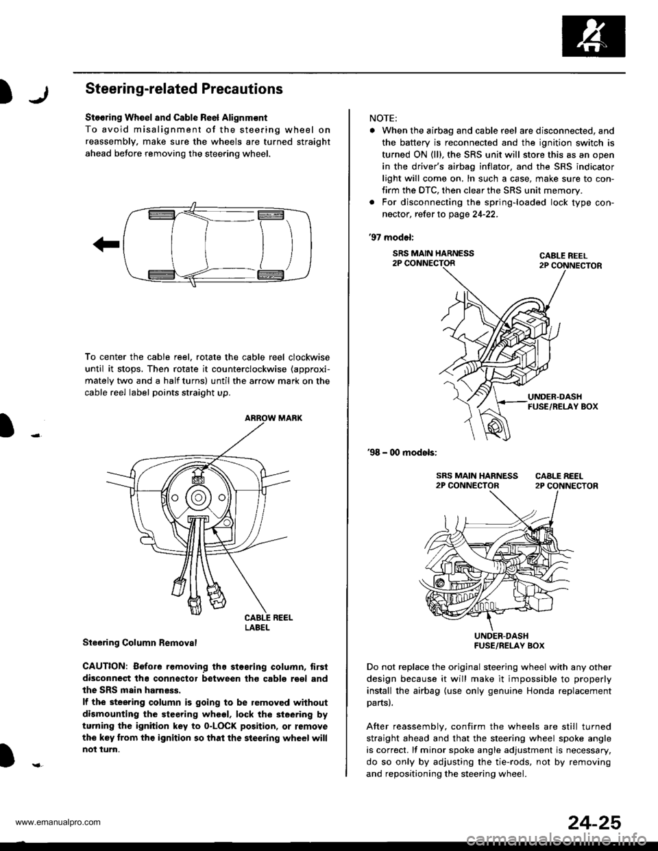
Stooring Wh€el and Csble Re6l Alignm€nt
To avoid misalignment of the steering wheel on
reassembly, make sure the wheels are turned straight
ahead beJore removing the steering wheel.
To center the cable reel, rotate the cable reel clockwise
until it stops, Then rotate it counterclockwise (approxi-
mately two and a half turns) until the arrow mark on the
cable reel label points straight up.
Steering Column Bemoval
CAUTION: Before removing the stosring column, tirsi
disconneqt tha connsctor between tho cabls roel and
the SRS main harness.
lf the steering column is going to be removed without
dismounting the steering wheel, lock the sieering by
turning the ignition key to o-LOCK position, or remove
the key trom the ignition so that the steering wheel will
not turn.
LABEL
NOTE:
. When the airbag and cable r6el are disconnected, and
the battery is reconnected and the ignition switch is
turned ON (ll), the SRS unit will store this as an open
in the driver's airbag inflator, and the SRS indicator
light will come on, In such a case, make sure to con-
firm the DTC, then clear the SRS unit memory.
. For disconnecting the spring-loaded lock type con-
nector, refer to page 24-22.
'97 model:
SRS MAIN HARNESS2P CONNECTORCABLE REEL2P CONNECTOR
'98 - 00 models:
UNDER-DASHFUSE/RELAY BOX
Do not replace the original steering wheel with any other
design because it will make it impossible to properly
install the airbag (use only genuine Honda replacement
partsl.
After reassemblv, confirm the wheels are still turned
straight ahead and that the steering wheel spoke angle
is correct. lf minor spoke angle adjustment is necessary,
do so only by adjusting the tie-rods, not by removing
and repositioning the steering whee .
24-25
www.emanualpro.com
Page 1323 of 1395
Troubleshooting
Self-diagnostic Procedures
The self-diagnostic function of the SRS system allows it to locate the causes of system problems and to store this informa-
tion in memory, For easier troubleshooting, this data can be retrieved via a data link circuit.
. When you turn the ignition switch ON (ll). the SRS indicator will come on. lf it goes off after six seconds, the system is
normal.
. lf there is 8n abnormality, the system locates and defines the problem. stores this information in memory, and turns
the SRS indicator light on. The data will remain in the memory even when the ignition switch is turned off or if the bat-
terv is disconnected.
. When you connect the SCS service connector to the service check connector (2P), and turn the ignition switch ON (ll),
the SRS indicator light will indicate the diagnostic trouble code (DTC) by the number of blinks.
. After reading and recording the DTC, proceed with the troubleshooting forthis code.
Precsutions
. Use only a digital multimeter to check the system. lf it's not a Honda multimeter. make sure its output is 10 mA (0.01 A)
or less when switched to the smallest value in the ohmmeter range. A tester with a higher output could damage the
airbag circuit or cause accidental airbag deployment and possible injury.
. Whenever the ignition switch isON (ll). or has been turned OFF for less than three minutes, be careful nottobumpthe
SRS unit; the airbags could accidentally deploy and cause damage or injuries.
. Before you remove the SRS main harness, disconnect the airbag and tensioner connectors (see page 24-23).
. Make sure the battery is sufficiently charged (see section 23). lf the battery is dead or low, measuring values won't be
correct.
. Do not touch a tester probe to the terminals in the SRS unit or harness connectors, and do not connect the terminals
with a jumper wire. Use only the backprobe set and the SCS service connector.
For backprobing spring-loaded lock type con nectors, .efet to page 24-22.
Reading the DTC
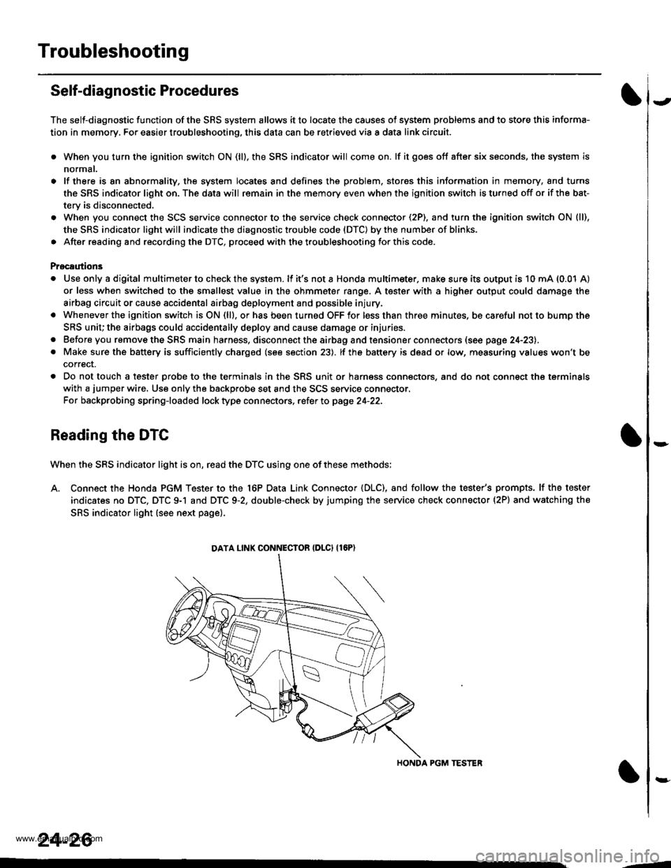
When the SRS indicator light is on, read the DTC using one of these methods;
A. Connect the Honda PGM Tester to the 16P Data Link Connector {DLC), and follow the tester's prompts. lf the tester
indicates no DTC, DTC 9-1 and DTC 9-2, double-check by jumping the service check connector (2P) and watching the
SRS indicator light (see next page).
HONDA PGM TESTER
DATA LINK CONNECIOR {DLCI {16P)
24-26
,1
www.emanualpro.com
Page 1324 of 1395
)
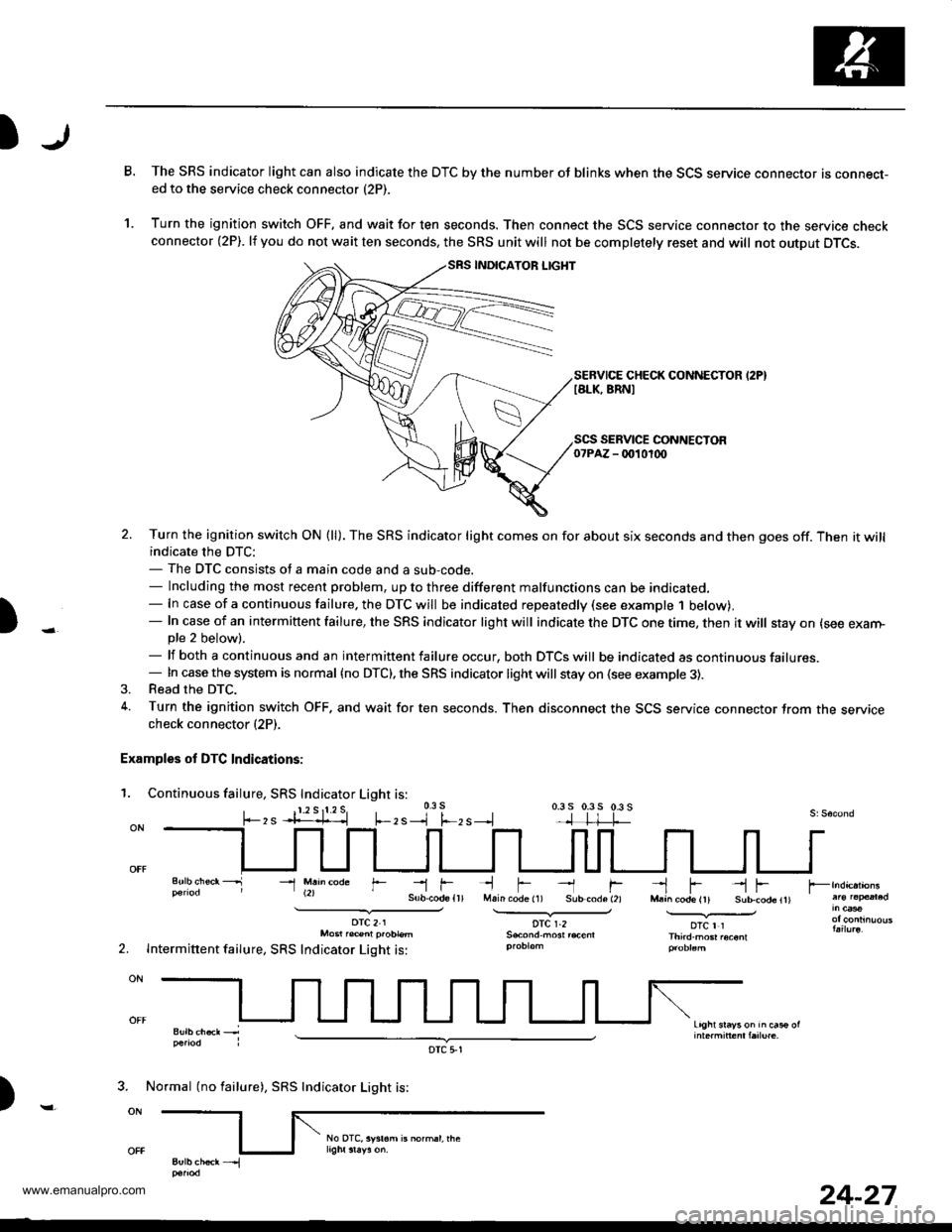
B.The SRS indicator light can also indicate the DTC by the number oJ blinks when the SCS service connector is connecr-ed to the service check connector (2P).
Turn the ignition switch OFF, and wait for ten seconds. Then connect the SCS service connector to the service checkconnector {2P). lf you do not wait ten seconds. the SRS unit will not be completely reset and will not output DTCS.
SEBVICE CHECK CONNECTOR I2PIIALK, BRNI
1.
)
SEBVICE CONNECTOR07PAZ - 0010100
2. Turn the ignition switch ON (ll). The SRS indicator light comes on for about six seconds and then goes off. Then it willindicate the DTC:- The DTC consists of a main code and a sub-code.- Including the most recent problem, up to three different malfunctions can be indicated.- In case of a continuous failure. the DTC will be indicated repeatedly (see example 1 below).- In case of an intermittent failure, the SRS indicator light will indicate the DTC one time, then it will stay on (see exarn-pte 2 below).- lf both a continuous and an intermittent failure occur, both DTCS will be indicated as continuous failures.- In case the system is normal {no DTC), the SRS indicator light will stay on (see example 3).3. Read the DTC.
4. Turn the ignition switch OFF. and wait for ten seconds. Then disconnect the SCS service connector Jrom the servicecheck connector (2P).
Examples of DTC Indications:
1. Continuous failure, SRS Indicator Light is:0.3 s
, s --l f.-, s --.l0.3 s 0.3 5 0.3 s
li-rMain code (1) Sub-code (2)
DTC r.2
--l fl-!
--1 M.h@de r--r f--l F --l FM.a^ code (rt Sub-cod6ltl.............v_otc I rThird.mGr .oconl
Light srayson in cas€ ol
2.
DTC21Mo6t r.@nl p.oblem
Intermittent failure, SRS Indicator Light is:
)
3. Normal (no failure), SRS Indicator Light is:
DTC 5,1
24-27
www.emanualpro.com
Page 1330 of 1395
SRS Indicator Light Wire Connections
SRS Indicator Light Power Circuit
DASHBOARD WIRE HARNESS
YEL
BLK
To UNDER-DASHFUSE/RELAY BOX <_
20P CONNECTOR
To GAUGEcsog + assEMBLy
SRS Indicator Light Control Circuit
SRS MAIN HARNESS
)-MAIN WIRE HARNESS
VAIVBIt
To UNDER-DASHFUSE/BELAY BOX2P CONNECTOR
c414MAIN WIRE HARNESS 3P CONNECTORTerminal side of msle t€rminals
c415MAIN wlRE HARNESS 24P CONNECTORTerminal aide of male terminals
c502DASHBOARD WIRE HARNESS 2OP CONNECTORWire side of lemslo terminsls
c503OASHBOARD WIRE HARNESS 24P CONNECTORWire side of female t€rminal3
c509DASHBOABD WIRE HARNESS 5P CONNECTORWire sid€ ot lemale te.minals
c801SRS MAIN HARNESS 2P CONNECTORwire side ol f.male terminals
c803SRS MAIN HARNESS 3P CONNECTORWire side ol female terminals
c806SRS MAIN HARNESS T8P CONNECTORWire side of lomrle terminals
)
24-33
www.emanualpro.com
Page 1332 of 1395
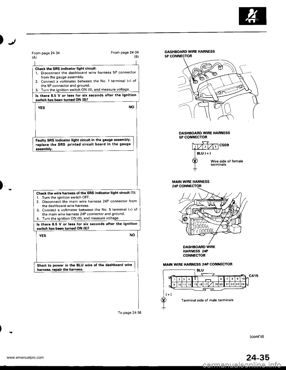
Chock th6 SRS indic.lor light circuit:1. Disconnect the dashboard wire harness 5P connector
from the gauge assembly.2. Connect a voltmeter between the No l terminal (+) o{
the 5P connector and grouncl.
3. Turn the ignition switch ON {ll), and measure voltage
ls thero 8.5 V or lats for 3ix second! aflsr the ignition
switch ha3 bo€n turnod ON (ll)7
YESNO
Fdulty SRS indicator light cilctlit in ths gauge sssomblY;
replaco tho SRS printod circuit board in the gauge
aasombly,
Chock th6 wire harn.$ of the SRS indicstor light circuh (11:
1. Turn the ignition switch OFF.2. Disconnect the main wire harness 24P connector from
the dashboard wire harness-3. Connect a voltmeter between the No 5 terminal (+) of
the ma;n wire harness 24P connecior and ground
4. Turn the ignition ON {ll), and measure voltage.
ls there 8,5 V or l€r3 tor six s€cond3 efter the ignilion
switch has bssn turnod ON llll?
YESNO
Short to powor in the BLU wire of tho dashbosrd wire
harne3s; Epait the harne3.s.
To page 24-36
Jt)
From page 24 34(A)From page 24-34(8)DASHBOARD WIRE HARNESS
5P CONNECTOR
DASHBOARD WIRE HARI{ESS5P CONI{ECTOR
c509
Wire side ol femaleterminals
)_
DASHBOARO WIREHARNESS 24PCONNECfOR
(cont'd)
MAIN WIRE HARNESS
MAIN WIRE HARI{ESS 2/tP COI{ ECTOR
Terminal side of male terminals
24-35
www.emanualpro.com