Page 1101 of 1395

Self-diagnosis Function
The heater control panel has a self-diagnosis function.
Running the Self-diagnosis Function'97 mod€l:
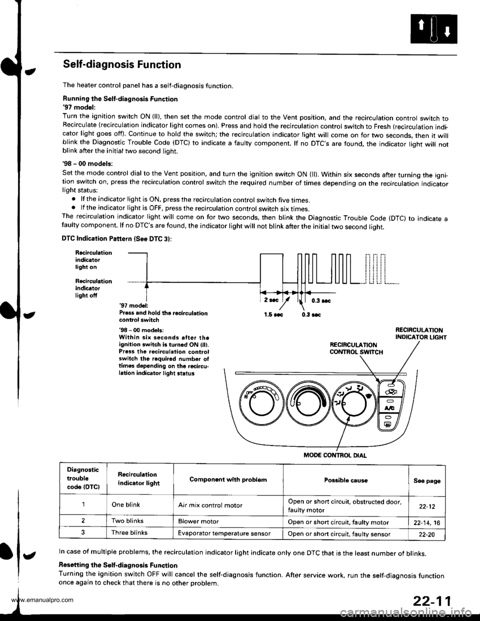
Turn the ignition switch ON {ll), then set the mode control dial to the Vent position, and the recirculation controt switch toRecirculate {recirculation indicator light comes on). Press and hold the recirculation control switch to Fresh (recirculation indi-cator light goes off). Continue to hold the switch; the recirculation indicator light will come on for two seconds. then it willblink the Diagnostic Trouble Code (DTC) to indicate a iaulty component. lf no DTC'S are found, the indicator liqht will notblink atter the initial two second light.
'98 - 00 models:
Set the mode control dial to the Vent position, and turn the ignition switch ON (ll). Within six seconds after turning the igni-tion switch on, press the recirculation control switch the required number of times depending on the recirculation indicatorlight status:
.lftheindicatorlightisON,presstherecirculationcontrol switch five times..lftheindicatorlightisOFF,presstherecirculationcontrol switch six I|mes.The recirculation indicator light will come on for two seconds, then blink the Diagnostic Trouble Code (DTC) to indicate afaulty component. lf no DTC'S are found, the indicator light will not blink after the initial two second liqht.
DTC Indicaiion Pattern {See DTC 3}:
Rocirculationindicatorlight on
Recirculrtionindicatorlighi off'97 model:P.ess and hold th6 recircul.tioncontrol switch'98 - 00 modek:Within six second3 atter theignition switch b turned ON (lll.Prass the rocirculation controlswitch the required number oltimes depending on the r6circu-lation indicator light striu3
,r*
/1.5 aaa 0.3 aac
RECIRCULANONINDICATOR LIGHT
In case of multiple problems, the recirculation indicator light indicate only one DTC that is the least number of blinks.
Resetiing the Solf.diagnosis Funqtion
Turning the ignition switch OFF will cancel the self-diagnosis function. After service work, run the self-diaqnosis functiononce again to check that there is no other Droblem.
MODE CONTROL OIAL
Diagnostic
trouble
code {DTCI
R6circulation
indicator lightComponent with problsmPossiblo causcSee page
'lOne blinkAir mix control molorOpen or short circuit, obstructed door,
faulty motor22-12
2Two blinksElower motorOpen or short circuit, faultv motor22-14,16
Three blinksEvaporator temperature sensorOpon or short circuit, faulty sensor22-20
t
www.emanualpro.com
Page 1301 of 1395

JFront Seat Belt RePlacement
SRS components are located in this area. Review the SRS
component locations, precautions, and procedures in this
section (24) before performing repairs or service ('98 - 00
models).
CAUTION: Check the front seat bslts for damago. and
replaco thom if necessary. Be careful not to damage
them during removal and in3tallation'
Front scat bolt:
1. Make sure you have the anti-theft code for the
radio, then write down the frequencies for the pre-
set buttons.
2. Disconnect the negative battery cable, and wait at
least three minutes before beginning work.
3. Slide the front seat forward fully.
4. Bemove (see section 20):
. Center pillar lower trim Pane
. Kick oanel
. Front side trim
5. '97 model: Remove the upper anchor cover and the
lower anchor caP.'98 - oO models: Remove the upper anchor cover
and pull the lower anchor cover back.
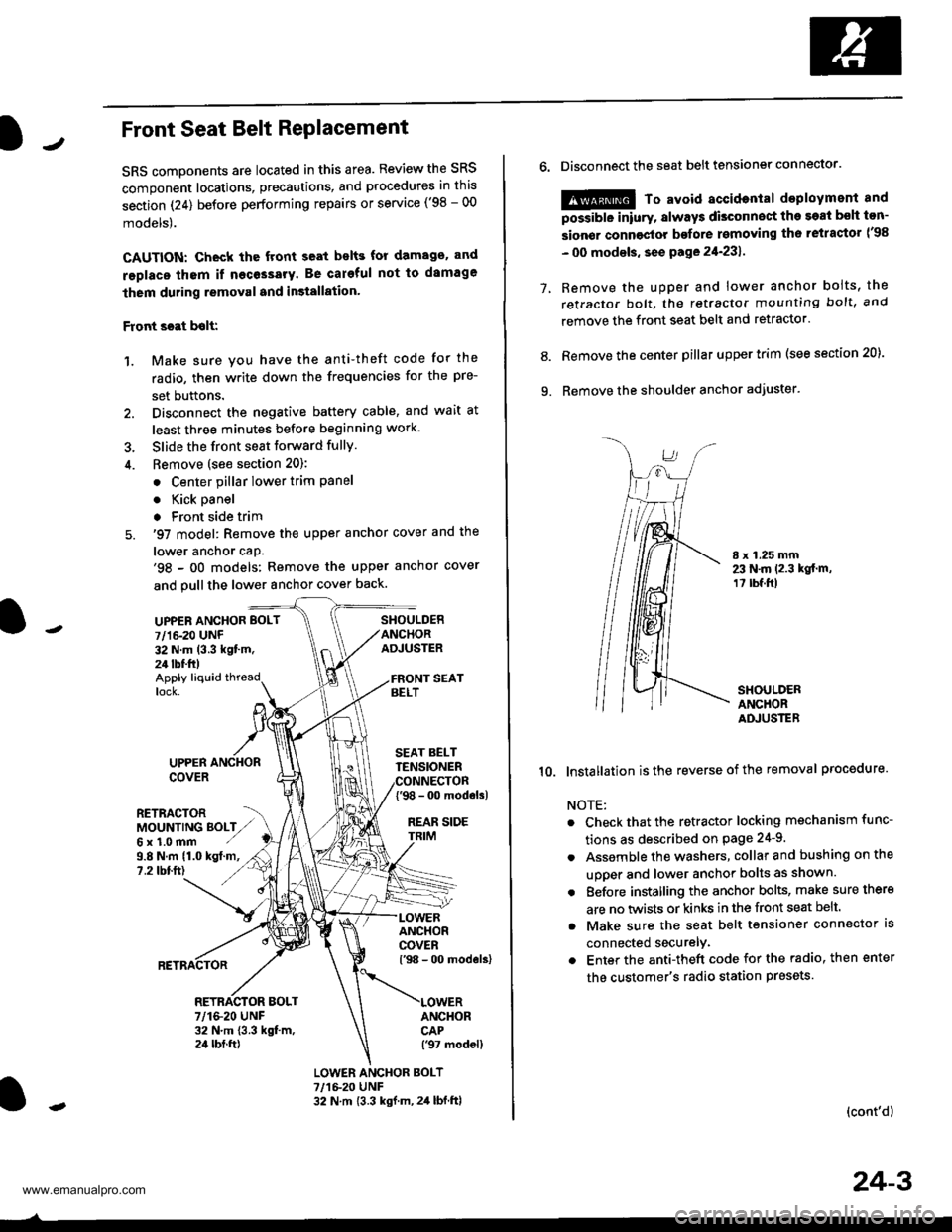
UPPEN ANCHOR BOLT
7/1&20 UNF32 N.m (3.3 kgt'm.24 tbf.ft)
SHOULDERANCHORADJUSTER
Apply liquid threadlock.
9.8 N.m (1.0 kgt.m,?.2 tbtft)
UPPERCOVER
RETRACTORMOUNTING BOLTZ,,Gx1.0mm ./
SEAT BELTTENSIONER
{'98 - 0o modols)
REAR SIDE
ANCHORCOVERl'98 - 00 models)
ANCHORCAP('97 modell
RETRACTOR BOLT7/1&20 UNF32 N.m 13.3 kgt m,24 tbt.ft)
LOWER ANCHOR BOLT?,/1&20 UNF32 N.m {3.3 kgf.m, 2,1 lbf.ftl
o.Disconnect the seat belt tensiongr connector.
@ To avoid accidontal deployment and
possibte inlury, always disconnect the soat bsh ton-
sion€r connoctor bofore rsmoving th6 retractor l'98
- 00 modsls, se€ pa ge 21-231 .
Remove the uDDer and lower anchor boits, the
retractor bolt, the retractor mounting bolt, and
remove the front seat belt and retractor.
Remove the center pillar upper trim (see section 20).
Remove the shoulder anchor adjuster.
7.
9.
8.
I x 1.25 mm23 N.m 12.3 kgt.m,1? tbf.ft)
SHOULDERANCHORADJUSTER
10. lnstallation isthe reverse of the removal procedure.
NOTE:
Check that the retractor locking mechanism func-
tions as described on Page 24-9.
Assemble the washers, collar and bushing on the
uooer and lower anchor bolts as shown.
Eefore installing the anchor bolts, make sure there
are no twists or kinks in the front seat belt.
Make sure the seat belt tensioner connector ls
connected securelv.
Enter the anti-theft code for the radio, then enter
the customer's radio station presets
(cont'd)
24-3
www.emanualpro.com
Page 1324 of 1395

)
B.The SRS indicator light can also indicate the DTC by the number oJ blinks when the SCS service connector is connecr-ed to the service check connector (2P).
Turn the ignition switch OFF, and wait for ten seconds. Then connect the SCS service connector to the service checkconnector {2P). lf you do not wait ten seconds. the SRS unit will not be completely reset and will not output DTCS.
SEBVICE CHECK CONNECTOR I2PIIALK, BRNI
1.
)
SEBVICE CONNECTOR07PAZ - 0010100
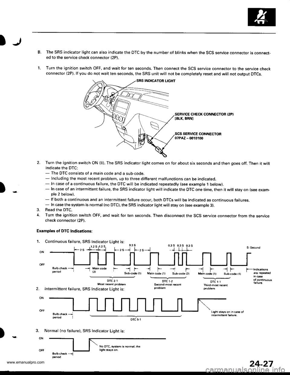
2. Turn the ignition switch ON (ll). The SRS indicator light comes on for about six seconds and then goes off. Then it willindicate the DTC:- The DTC consists of a main code and a sub-code.- Including the most recent problem, up to three different malfunctions can be indicated.- In case of a continuous failure. the DTC will be indicated repeatedly (see example 1 below).- In case of an intermittent failure, the SRS indicator light will indicate the DTC one time, then it will stay on (see exarn-pte 2 below).- lf both a continuous and an intermittent failure occur, both DTCS will be indicated as continuous failures.- In case the system is normal {no DTC), the SRS indicator light will stay on (see example 3).3. Read the DTC.
4. Turn the ignition switch OFF. and wait for ten seconds. Then disconnect the SCS service connector Jrom the servicecheck connector (2P).
Examples of DTC Indications:
1. Continuous failure, SRS Indicator Light is:0.3 s
, s --l f.-, s --.l0.3 s 0.3 5 0.3 s
li-rMain code (1) Sub-code (2)
DTC r.2
--l fl-!
--1 M.h@de r--r f--l F --l FM.a^ code (rt Sub-cod6ltl.............v_otc I rThird.mGr .oconl
Light srayson in cas€ ol
2.
DTC21Mo6t r.@nl p.oblem
Intermittent failure, SRS Indicator Light is:
)
3. Normal (no failure), SRS Indicator Light is:
DTC 5,1
24-27
www.emanualpro.com