Page 47 of 1395
Maintenance Schedule (for 1998 - 2000 Models)
oNormal Conditions
o
zo_u{:9
+:N
Foz9d
.E
Ed
EJ
€3
:
6
!
E
ooE
rl
!Li:
o2?
*F9r
i
E
B
i q =Y
h Ena q
sili:.E ; *;= - ^
i6: l.*:;=:--o
FEtr 5 S1
6!;: a3
;;;iB:
ti??
'66
EEoo
trtr
5A
.E
aor:
cj ct 6
E''i-;
3=?;
'r
p ^i ..i i
1 39:
r !!=
'Eoo P!i33 !
=;k E
I
.s
(5
!
l_
.j:
c>
E
E
oP
p!
!. ii
::
*c
:a
39l9=
eESl
::-G.
5< d9i=9'ti
E Ee Xe
+ i >= i
;ii5e:=F!-\
!;!a;
a; i 6 si E: P O
s=;sE
.!E
.!
.!
3
.9
.9;t
5>6-a
E
=
:E
-
a
!
aaaaaa
E
eE
aaaaaaa
aa
.9
aaaaoaaa
aaaa
aaaaaaa
aaaaa
aaaaaaa
aaa
EEE
sEg
a'6
I
2
a
3
E
,
.!
E
a
!
E.
!:
,9.9E
6a
p
E
!
d
!
E
.E
:
E.9
6
.F_
3
.s
rE
96
oq
€;
;.E F
--
3
p
,E
6
.9
,E.z
3
.9
E
z
t
o
!
6
E
3-8
www.emanualpro.com
Page 49 of 1395
Maintenance Schedule (for 1998 - 2000 Models)
OSevere Conditions
o
6
;
-E
.9
:.9)
.l:
E
=;
-9c
>ii
-i .:
-xi €
&,6 =
R3 !
!c 6.-j! .:*3: :t:4 3;:P:-eCFg:,.! o--iF Y e E
!€;3_
lP
IElo
IE
:
;.a
.9?s
3
!lE
a?.
6.s>
:
;
E
.>o
€
E
z
a
;l
+l.:l5l
il
:l
3li
.ql
FIEI
€lFI
ol9l
;l
:l:t,PI
o
zo_4
U;
*:R
F
z
;;;
o-
I
!
I
!
3
IE P5E 9
c, ci 6r3
9.:-6
:9
!|;>
oz-:Oo
Tl
t* -
JQ A
z*9
I
'6
i
E'� ^5} E:Y
; EsI EEgeY.:
sINI!;; 6 *^; * r; F;,^!
hEz!:i9
EE€; e1e= a q::6go-.!5.6
;;;iF3
o6 a
.F_ Z
EEoo
EE
=a
{ai
;i3
a--q
eqo? R
s= k;
'-<
:F
ln
c ci.ii
-:oo IIs33 Eii q... "
=ik F
I
'3
(,
'
:
;
f-p
c>
E
E
.9 it
oE
:+
E!
!o
ib
.i:
o-
s3=l|il
t 3=EeES t€ii;t
!: ir:
€ !,3€;E E3 ig
EE;bFj=-;H:26anii 6:.s FEE.ESe
-ii d:1
9;.: 6:
l;;"3
H iq Hrac;a:
E
E
E
-
6
!
aaaaa
E
E
..i=
IE
-
aaa
aaaoaaa
o
.9
->
aaaaaaa
aaao
aaaaoaoa
aaoaa
aaaaaoa
aaa
:
=
j
E
n
E
.=
t
.E
I
!
.9.9
!
.g
a
!
a
E
.9
6
E€:
69:
3-10
www.emanualpro.com
Page 51 of 1395

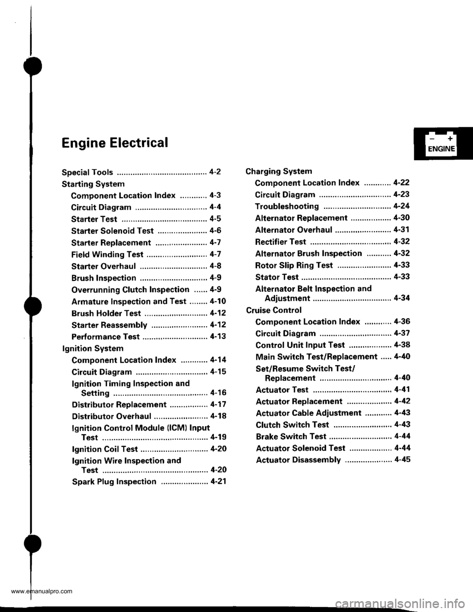
Engine Electrical
Speciaf Tools ............. 4-2
Starting System
Component Location Index ............ 4-3
Circuit Diagram ................................ 4-4
Starter Test ........... 4-5
Starter Solenoid Test ...................... 4'5
Starter Replacement ....................... 4-7
Field Winding Test ........................... 4-7
Starter Overhaul ............................,. 4-8
Brush Inspection ...........................,., 4-9
Overrunning Glutch Inspection ...... 4-9
Armature lnspection and Test ........4-10
Brush Holder Test ............................ 4-12
Starter Reassemb|y ......................... 4-1 2
Perf ormance Test ............................. 4- 1 3
lgnition System
Component Location Index ............ 4-14
Circuit Diagram ................................ 4-15
lgnition Timing Inspection and
Setting .......................................... 4-16
Distributor Replacement ........,........ 4-17
Distributor Overhaul .............,,......... 4-18
lgnition Control Module (lCM) Input
Test ..............................,................ 4-19
fgnition Coil Test .............................. 4-2O
lgnition Wire Inspection and
Test ............................................... 4-20
Spark Plug Inspection ..................... 4-21
-+
ENGINE
Charging System
Component Location Index ............ 4-22
Circuit Diagram ....................,........... 4-23
Troubleshooting .............................. 4-24
Alternator Replacement ..........,....... 4-30
Alternator Overhaul .......,,................ 4-31
Rectifier Test .........4-32
Alternator Brush Inspection ........... 4-32
Rotor Slip Ring Test ........................ 4-33
Stator Test ............. 4-33
Alternator Belt Inspection and
Adiustment ........4-34
Gruise Control
Component Location Index .,,,........ 4-36
Circuit Diagram ................................ 4-37
Control Unit Input Test ................... 4-38
Main Switch Test/Replacement ..... 4-40
Set/Resume Switch Test/
Replacement .......................,........ 4'40
Actuator Test ....,,., 4-41
Actuator Replacement ...............,.... 4-42
Actuator Cable Adiustment ............ 4-43
Clutch Switch Test .......................... 4-43
Brake Switch Test .................. .......... 4-44
Actuator Solenoid Test .............. ...,. 4-44
Actuator Disassembly ..................... 4-45
www.emanualpro.com
Page 61 of 1395
I
NOT GOOD
5. Check the mica depth. lf necessary, undercut the
mica with a hacksaw blade to achieve proper depth.
lf the service limit cannot be maintained, reDlace
the armature.
MICA DEPTI{
Commutator Mica Depth
Standard (Nsw): 0.5 - 0.8 mm 10.02 - 0.03 inl
Servico Limit: 0.2 mm (0.008 in)
Check for continuity between the segments of the
commutator. lf an open circuit exists between any
segments. replace the armature.
6.
COMMUTATOR
4-11
7. Place the armature on an armature tester. Hold a
hacksaw blade on the armature core.
lf the blade is attracted to the core or vibrates while
the core is turned. the armature is shorted. Replace
the armature.
8. With an ohmmeter, check that no continuity exists
between the commutator and armature coil core,
and between the commutator and armature shaft. lf
there is continuity. replace the armature,
cotL coRE
www.emanualpro.com
Page 89 of 1395

Disconnest the lilP connector from the control unit.
Csvity WireTest condition
R€conn€ct tho 14P connGctor to the control unit.
Test: Desired resultPossible cause it result is not obtained
BRNAr'VHTUnder all conditionsCheck for resistance to groundl
There should be 80 - 120 o.
Faulty actuator solenoid
Poor ground (G202)
An open in the wire1BRNUnder all conditionsCheck for resistance to groundl
There should be 40 - 60 0.
11BRN/BLKUnder all conditionsCheck for resistance to ground:
There should be 70 - 110 O.
2GRY
lgnition switch ON (ll),
main switch ON and
brake pedal depressed,
then released
Check for voltage to ground:
There should be 0 V with the pedal
depressed and battery voltage with
the pedal released.
. Faulty brake switch. An open in the wire
BLKUnder all conditionsCheck for continuity to ground:
There should be continuity.
. Poor ground (G401). An open in the wire
5GRNMHT
Brake pedal depressed,
then released
Check for voltage to ground:
There should be battery voltage with
the pedal depressed, and 0 V with
the pedal released.
Blown No.52 1'15 Alfuse in the
under-hood fuse/relay box
Faulty brake switch
An open in the wire
LT GRN/
RED
Set button pushedCheck for voltage to ground:
There should be battery voltage.Blown No. 52 {'15 A} fuse in the
under-hood fuse/relay box
Faulty horn relay
Faulty sevresume switch
Faulty cable reel
An open in the wire7LT GRN/
BLK
Resume button pushed
10RED/BLU
lgnition switch ON lll)Attach to ground:
Cruise indicator light in the gauge
assembly should come on.
Elown bulbBlown No. 25 (7.5 A) tuse in theunder-dash fuse/relay box
Faulty dimming circuit in the gauge
assembly
An open in the wire
ELU^r'r'HT
lgnitjon switch ON {ll}and main switch ON;
raise the front of the
vehicle, block one wheel
and rotate the other
wheel slowly.
Check for voltage between the
ELUA/VHT @ and BLK O terminalsl
There should be 0 - 5 V or more-0 - 5 V or more repeatedly.
Faulty vehicle speed sensor (VSS)
An open in the wire
r3LT GRN
lgnition switch ON {ll}and main switch ONCheck for voltage to ground:
There should be battery voltage.
Blown No. 14 (7.5 A) fuse in theunder-dash fuse/relay box
Faulty main switch
An open in the wire
l4PNK
A'/T: Shift lever in E, EotE
lvl/T: Clutch pedal
releaseo
Check for continuity to ground:
There should be continuity.NOTE: There should be no continu-
ity when the shift lever is in otherpositions or when the clutch pedal is
oepresseo.
Faulty A/f gear position switch 1A,/TlFaulty or misadjusted clutch switch
fi{/r)Poor ground (G101)
An open in the wire
BLU
Start tho engine. turnthe main switch ON, anddrive the vehicle over 25
mph (40 km/h)with the
crurse control set
Check for voltage to ground:
There should be approx.5 V
. Faulty cruise control unit. Shod to ground
*: '98 - 00 models with Automatic Transmission.
4-39
www.emanualpro.com
Page 90 of 1395

Cruise Control
1.
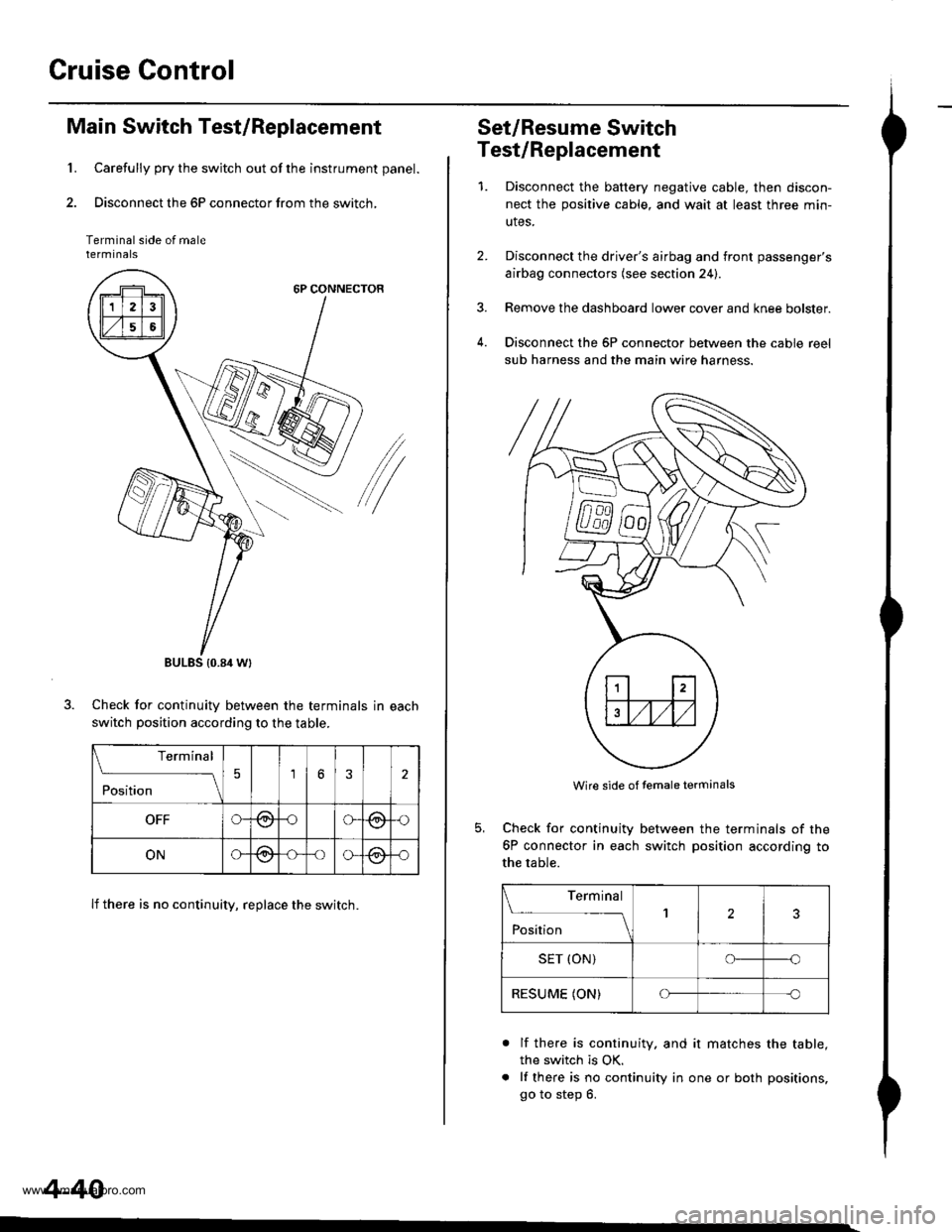
Main Switch Test/Replacement
Carefully pry the switch out of the instrument panel.
Disconnect the 6P connector from the switch,
Terminal side of malerermtnats
6P CONNECTOR
/
Check for continuitv between the terminals in each
switch position according to the table.
lf there is no continuity, replace the switch.
BULES {0.84 Wt
Terminal
;;;
-_\56
OFFG-@oG(9,{)
ONG@-oo-@-o
4-40
Set/Resume Switch
Test/Replacement
1.Disconnect the baftery negative cable, then discon-
nect the positive cable, and wait at least three min-
utes.
Disconnect the driver's airbag and front passenger's
airbag connectors (see section 24).
Remove the dashboard lower cover and knee bolster.
Disconnect the 6P connector between the cable reel
sub harness and the main wire harness.
4.
Wire side of temale terminals
Check for continuity
6P connector in each
the table.
between the terminals of the
switch position according to
Terminal
;;;
--_l2
SET (ON)o--o
RESUME (ON)Cf-c
a
lf there is continuity. and it matches the table,
the switch is OK.
lf there is no continuity in one or both positions,
go to step 6.
www.emanualpro.com
Page 99 of 1395
6. Disconnect the engine control module (ECM)/power-
train control module (PCM) connectors from the ECM/
PCM.
7. Disconnect the main wire harness connector.
Remove the grommet and wire harness clamps, then
pull out the EcM/Pclvl connectors.
6x1.0mm11 N.m 11.1 kgl.m,8lbf.ftl
CONNECTOR
GROMMET
L Disconnect the engine wire harness connectors on
the left side of the engine compartment.
ENGINE WIREHARNESS CONNECTORS
(cont'd)
5-3
www.emanualpro.com
Page 123 of 1395

Timing Belt
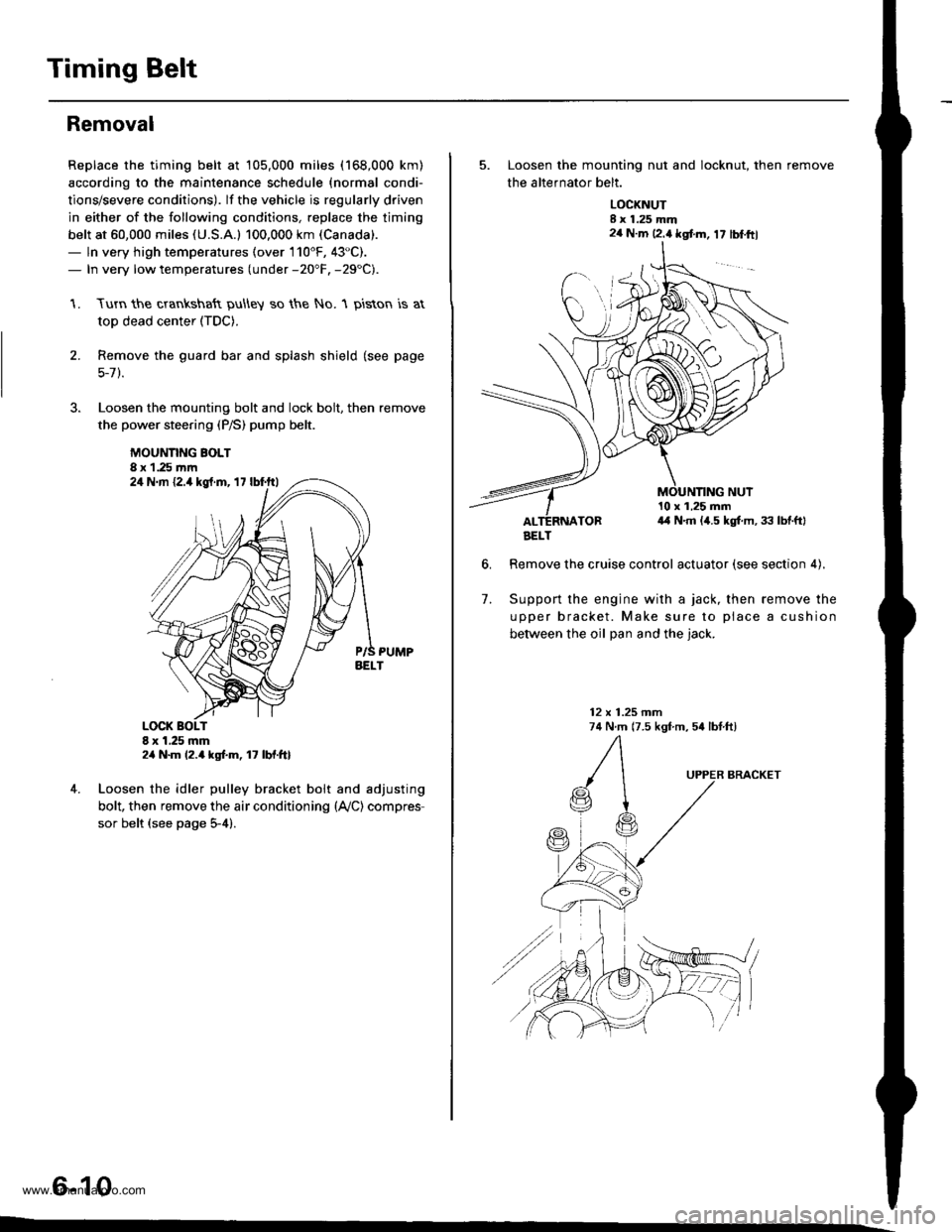
Removal
Replace the timing belt at 105,000 miles (168,000 km)
according to the maintenance schedule {normal condi-
tions/severe conditions). lf the vehicle is regularly driven
in either of the following conditions, replace the timing
belt at 60,000 miles (U.S.A.l 100.000 km (Canada).
- ln very high temperatures (over 110'F, 43"C).- In very low temperatures (under -20"F. -29"C).
Turn the crankshaft pu\ley so the No. 1 piston is at
top dead center (TDC).
Remove the guard bar and splash shield (see page
5-7 ).
Loosen the mounting bolt and lock bolt. then remove
the power steering (P/S) pump belt.
MOUNNNG BOLT8 x 1.25 rnm
1.
2.
,l
4. Loosen the idler pulley bracket bolt and adjusting
bolt, then remove the air conditioning (lVC) compres
sor belt (see page 5-4).
6-10
24 N.m {2.4 kgt.m, 17 lbf.ftl
24 N.m 12.4 kgf.m, lt lbf.ftl
5. Loosen the mounting nut and locknut, then remove
the altefnator belt.
LOCKNUTI x 1.25 mm2a N.m 12.4 kgt m, 17 lblftl
6.
10 x 1,25 mm4,1 N.m (,1.5 kgt m, 33 lbtftl
Remove the cruise control actuator (see section 4).
Support the engine with a jack, then remove the
upper bracket. Make sure to place a cushion
between the oil Dan and the iack.
12 x 1.25 mm74 N.m (7.5 kgf m, 54 lbtftl
7.
BRACKET
AELT
www.emanualpro.com