Page 681 of 1395
Transfer Assembly
Removal
@ Make sure the lifts, iacks, and safety
stands are placed properly (see section 11.
1. Raise the front of the vehicle, and make sure it is
supported securely.
2. Set the parking brake, and block both rear wheels
securelv.
3 Drain the automatic transmission fluid (ATF).
Reinstall the drain plug with a new sealing washer'
DRAIN PLUG'18 x'1.5 rnm49 N.m 15.0 kgf.m, 36 lbl.ftl
4. Remove the guard bar and the splash shield.
GUARD 8AR
14-165
5.Disconnect the primary heated oxygen sensor
{Primary HO2S) connector.
Remove exhaust pipe A.
SELF-LOCKINGNUTBeplace.
7.
SEI-F.LOCKINGNUTReplace.
NUTReplace
Remove the shift cable cover.
Remove the snap pin and control pin, then separate
the shift cable from the control lever. Do not bend
the shift cable excessively.
(cont'd)
www.emanualpro.com
Page 686 of 1395
Transmission
Removal (cont'd)
8. Disconnect the mainshaft sp€ed sensor, the shift
control solenoid valve, and the linear solenoid con-
necrors,
Remove the drain plug. and drain the automatic
transmission fluid {ATF). Reinstall the drain plug
with a new sealing washer.
DRAIN18 x 1.5 mm4e N.m rs.o ksr.m. 36 rbrft) ;:i:$: *o"*."
SENSOR CONNECTOR
14-170
OAMPER FORKReplace.
10. Remove the guard bar and the splash shield.
Remove the cotter pins and castle nuts, then sepa-
rate the ball joints from the lower arms (see section
18).
Remove the right damper fork bolt, then separateright damper fork and damper.
11.
12.
SELF.LOCKINGNUTReplace.
CASII.E NUT
DAMPER FORKBOLT
DAMPER PINCH BOLT
www.emanualpro.com
Page 800 of 1395

Real-time 4WD-Dual Pump System
Troubleshooting (Automatic Transmissionl
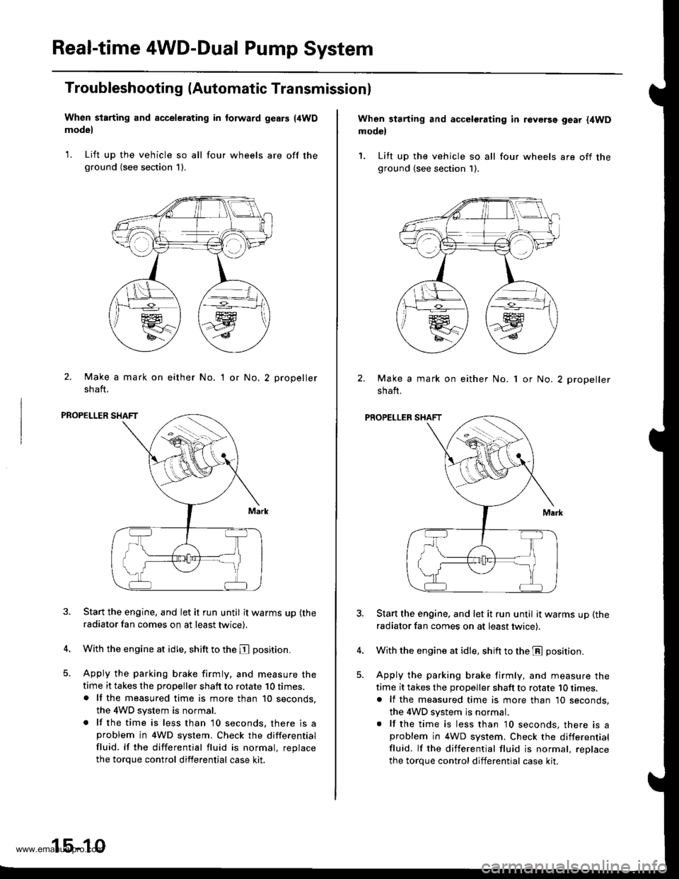
When starting and accelerating in forward gesrs {4WDmodel
1. Lift up the vehicle so all four wheels are off theground (see section 1).
2. Make a mark on either No.
shaft.
'I or No.2 propeller
PROPELLER SHAFT
Start the engine, and let it run until it warms up (the
radiator fan comes on at least twice).
With the engine at idle. shift to the E position.
Apply the parking brake firmly. and measure thetime it takes the propeller shaft to rotate 10 times.. lf the measured time is more than 10 seconds,
the 4WD system is normal.
. lf the time is less than 10 seconds, there is aproblem in 4WD system. Check the differential
fluid. lf the differential fluid is normal, replace
the torque control differential case kit.
15-10
When starting and accelerating in revGrsg gear {4WDmodel
1. Lift up the vehicle so all four wheels are off theground (see section 1).
Make a mark on either No.
shaft.
1 or No. 2 propeller
PROPELLER SHAFT
Start the engine. and let it run until it warms up (the
radiator fan comes on at least twicei.
With the engine at idle, shift to the E position.
Apply the parking brake firmly, and measure the
time it takes the proDeller shaft to rotate 10 times,. lf the measured time is more than 10 seconds,
the 4WD system js normal.. lf the time is less than 10 seconds, there is aproblem in 4WD system. Check the differential
fluid. lf the differential fluid is normal, reolace
the torque control differential case kit.
www.emanualpro.com
Page 802 of 1395

Real-time 4WD-Dual Pump System
Troubleshooting (Automatic Transmission/Manual Transmission)
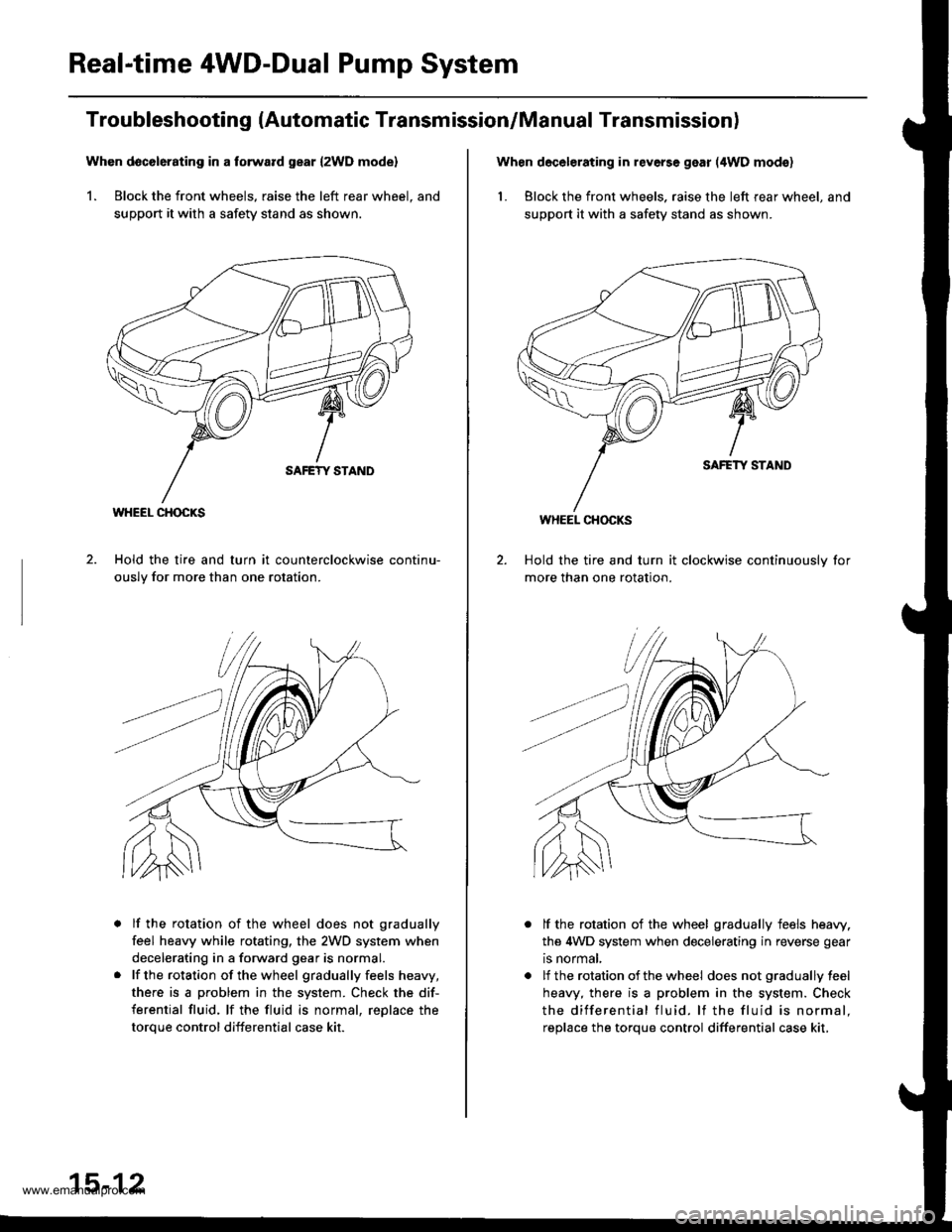
Whon d6c6l6rating in a torward gear {2WD mode}
1. Block the front wheels, raise the left rear wheel. and
support it with a safety stand as shown.
Hold the tire and turn it counterclockwise continu-
ouslv for more than one rotation.
lf the rotation of the wheel does not gradually
feel heavy while rotating, the 2WD system when
decelerating in a forward gear is normal.
lf the rotation of the wheel gradually feels heavy,
there is a problem in the system. Check the dif-
ferential fluid, lf the fluid is normal, reDlace the
toroue control differential case kit.
WHEEL CHOCKS
15-12
When decelerating in reverse gear (4WD mod€)
1. Block the front wheels. raise the left rear wheel, and
suppo( it with a safety stand as shown.
Hold the tire and turn it clockwise continuouslv for
more than one rotation.
lf the rotation of the wheel gradually feels heaw.
the 4WD system when decelerating in reverse gear
is normal,
lf the rotation of the wheel does not gradually feel
heavy, there is a problem in the system. Check
the differential fluid. lf the fluid is normal.
reolace the torque control differential case kit,
WHEEL CHOCKS
www.emanualpro.com
Page 860 of 1395

Rack Guide Adjustment
1.
6.
7.
5.
4.
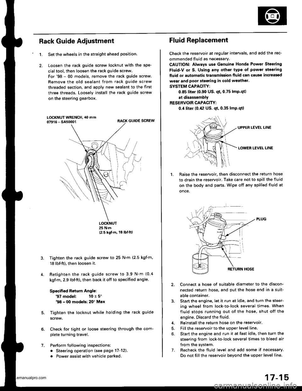
Set the wheels in the straight ahead position.
Loosen the rack guide screw locknut with the spe-
cialtool, then loosen the rack guide screw.
For'98 - 00 models, remove the rack guide screw.
Remove the old sealant from rack guide screw
threaded section, and apply new sealant to the first
three threads. Loosely install the rack guide screw
on the steering gearbox.
RACK GUIDE SCREW
LOCKNUT25 N.m
12.5 kgt m, 18lbtftl
Tighten the rack guide screw to 25 N.m (2.5 kgf'm,
18 lbf.ft), then loosen it.
Retighten the rack guide screw to 3.9 N'm (0.4
kgf.m, 2.9 lbf.ft), then back it off to specified angle.
Specified Return Anglo:
37 model: 10 r 5"'98 - 00 modeb: 20' Max
Tighten the locknut while holding the rack guide
screw.
Check for tight or loose steering through the com-
plete turning travel.
Perform following inspections:
. Steering operation (see page 17-12).
. Power assist with vehicle parked
Fluid Replacement
Check the reseryoir at regular intervals, and add the rec-
ommended fluid as necessary.
CAUTION: Always use Gsnuine Honda Power Steering
Fluid-V or S. Using any other type of power steering
tluid or automatic transmission fluid can cause increassd
wear and poor steering in cold w3athel.
SYSTEM CAPACITY:
0.85 liter {0.90 US. qt. 0.75 lmp.qtl
at disasssmbly
RESERVOIR CAPACITY:
0.,1 liter (0.42 US. gt, 0.35 lmp.qi)
UPPEN LEVEL LINE
LOWER LEVEL LINE
1.Raise the reservoir. then disconnect the return hose
to drain the reservoir. Take care not to spill the fluid
on the body and parts. Wipe off any spilled fluid at
once.
2, Connect a hose of suitable diameter to the discon-
nected return hose, and put the hose end in a suit-
able container.
3. Stan the engine. let it run at idle, and turn the steer-
ing wheel from lock-to-lock several times. When
fluid stops running out of the hose, shut off the
engine. Discard the fluid.
4. Beinstallthe return hose on the reservoar.
5. Fill the reservoir to the upper level line,
6. Start the engine and run it at fast idle. then turn the
steering from lock-to-lock several times to bleed air
from the system.
7. Recheck the fluid level and add some if necessary.
Do not fill the reservoir beyond the upper level line.
www.emanualpro.com