Page 246 of 1395
S)stern Dessr\ptron
ENGINEWIREHARNESS
c1z2
(PCM.AI
System Connectors lDash and Floor] -'97 Model {cont'd)
MAIN WIREHARNESS
//l
tao,
{PCM.D}
11-44
www.emanualpro.com
Page 248 of 1395
System Description
System Connectors lEngine Gompartment] -'98 Model
MAIN WIREHARNESS
UNDER.HOODFUSE/RELAYBOX
ENGINEw|REHARNESS
*2: USA
11-46
www.emanualpro.com
Page 250 of 1395
System Description
System Connectors lEngine Compartmentl -'98 Model (cont'd)
MAIN WIRE
ENGINEWIREHARNESS
www.emanualpro.com
Page 252 of 1395
System Description
System Gonnectors lEngine Compartment] -'99 - 00 Models
MAIN WIREHAENESS
UNDER.HOOOFUSE/RELAYBOX
ENGINEWIREHARNESS
www.emanualpro.com
Page 254 of 1395
System Description
System Gonnectors [Engine Compartment] -'99 - 00 Models {cont'dl
MAIN WIREHARNESS
11-52
www.emanualpro.com
Page 258 of 1395
System Description
System Connectors lDash and Floorl -'98 - 00 Models (cont'd]
c510DASHBOARD WIREHARNESS
MAIN WIEEHARNESS
'4: '99 - 00 models
1 1-56
www.emanualpro.com
Page 260 of 1395
System Description
ENGINEWIREHARNESS
System Conneetors lDash and Floorl -'98 - 00 Models (cont'dl
DASHBOARDWIRE HARNESSMAIN WIB€HARNESS
c,47(ECM/PCM.A}
c121(ECM/PCM-8)
n
lno,
(PCM.D}
www.emanualpro.com
Page 364 of 1395

ldle Gontrol System
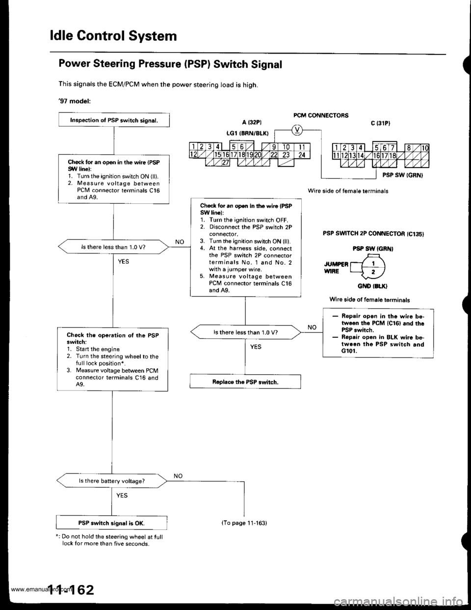
Power Steering Pressure (PSP) Switch Signal
This signals the ECM/PCM when the power steering load is high.
'97 model:
*: Do not hold the steering wheel at tulllock for more than five seconds,
Wire side of female terminals
PSP SWTTCH 2P CONNECTOR 1C135)
PSP SW (GRN)
JUMPER T_7 1 \vnRE t--f r)
GND IBLK}
Wire 3id6 of female terminals
Inspection ot PSP switch signal.
Check for an open in the wire {PSPSYV line):1. Turn the ignition switch ON (ll).2. Measure voltage betweenPCN4 connector terminals C16and A9.
Check tor an open in lhe wire (PSPSW linel:1. Turn the ignition switch OFF.2. Disconnect the PSP switch 2Pconnecror,3. Turn the ignition switch ON (ll).4. At the harness side, connectthe PSP switch 2P connectorterminals No. 1 and No. 2with a jumper wire.5, Measute voltage betweenPCM connector terminals C16and A9.
ls there less than 1.0 V?
- Ropsir open in the wi.e be-twoon the PCM lcl6l and thePSP switch.- Ropdir open in BLK wire be-tween the PSP switch andG101.
ls there less than 1.0 V?Check the operation oI lhe PSPswitch:1. Stan the engine2. Turn the steering wheelto thefull lock position*.
3. Measure voltage between PCMconnector terminals C16 andA9.
ls there battery voltage?
PSP switch signal is OK.(To page 11-163)
www.emanualpro.com