Page 469 of 1395
Countershaft Assembly
Clearance Inspection (cont'dl
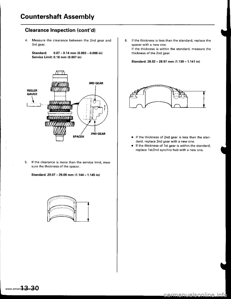
4. Measure the clearance between the 2nd qear and
3rd gear.
Standard: 0.07 - 0.1,1 mm (0.003 - 0.006 inl
Service Limit:0.18 mm (0.007 inl
FEET.ERGAUGE
!t .-]
lf the clearance is more than the service limit. mea-
sure the thickness of the spacer.
Standard: 29.07 - 29.09 mm (l.14il - 1.145 inl
13-30
6. lf the thickness is less than the standard, reDlace the
spacer wrln a new one.
lf the thickness is within the standard, measure the
thickness of the 2nd gear.
Standald: 28.92 - 28.97 mm (1.139 - 1.141 in)
lf the thickness of 2nd gear is less than the stan-
dard, replace 2nd gear with a new one.
lf the thickness of lst gear is within the standard,
replace 1sv2nd synchro hub with a new one.
www.emanualpro.com
Page 472 of 1395
Reassembly
Note these items during reassembly:
. Press the 3rd, 4th, and sth gear on the countershaft
without lubrication.
. When installing the 3rd, 4th. and sth gears, suppon
the shaft on steel blocks and install the gears using a
press.
. Refer to page 13-28 for reassembly sequence.
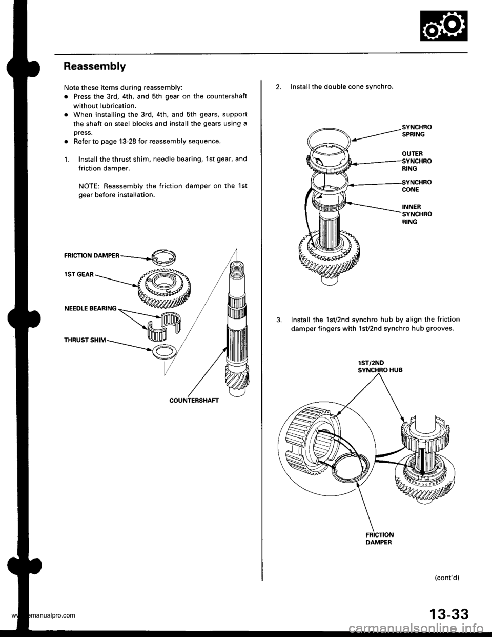
1. Install the thrust shim, needle bearing, 1st gear, and
friction damper.
NOTE: Reassembly the friction damper on the lst
gear before installation.
rnrcrroru orn,leen ----.-4O)
lST GEAR
NEEDLE BEARING
THRUST SHIM
2. Install the double cone synchro.
3. Install the 1sv2nd synchro hub by align the friction
damper fingers with 1svznd synchro hub grooves.
(cont'd)
OUTER
lST/2ND
13-33
www.emanualpro.com
Page 475 of 1395
Synchro Sleeve, Synchro Hub
Inspection
1.Inspect gear teeth on all synchro hubs and synchro
sleeves for rounded off corners, which indicate
Install each synchro hub in its mating synchro
sleeve, and check for freedom of movement.
NOTE: lf replacement is required, always replace
the synchro sleeve and synchro hub as a set.
SYNCHROSLEEVE
SYNCHBOHUB
13-36
LONGER ?EETH
Installation
When assembling the synchro sleeve and synchro hub,
be sure to match the three sets of longer teeth ('120
degrees apart) on the synchro sleeve with the three sets
of deeper grooves in the synchro hub. Do not installthe
synchro sleeve with its longer teeth in the lsv2nd syn-
chro hub slots because it will damage the spring ring.
SYNCHRO
SYNCHBOSI.EEVE
www.emanualpro.com
Page 476 of 1395

Synchro Ring, Gear
Inspection
Inspect the synchro ring and gear.
Ar lnspect the inside of the synchro ring for wear.
B: lnspect the synchro sleeve teeth and matching
teeth on the synchro ring for wear (rounded of0.
CCGOOO WORN
Cr Inspect the synchro sleeve teeth and matching
teeth on the gear tor wear (rounded off).
,,
u (-l
GOOO WORN
D: Inspect the gear hub thrust surface for wear.
E: Inspect the cone surface lor wear and roughness.
F: Inspect the teeth on all gears for uneven wear,
scoring, galling, and cracks.
2. Coat the cone surface of the gear with oil, and place
the synchro ring on the matching gear. Rotate the
synchro ring, making sure that it does not slip.
Measure the clearance between the synchro ring
and gear allthe way around.
NOTE: Hold the synchro ring against the gear even-
ly while measuring the clearance.
Synchro Ring-to-Gear Clearance
Standard: 0.85 - 1.10 mm (0.033 - 0.0,lil in)
Service Limit: 0.,1 mm 10.02 inl
Double Cone Synchro-lo-Goar Clearance
Standard:
@: {Outer Synchro Ring to Synchto Conel
0.5 - 1.0 mm (0.02 - 0.04 in)
€): {synchro cone to Geal)
0.5 - 1.0 mm (0.02 - 0.0i1inl
@: louter Synchro Ring to Gearl
0.95 - 1.68 mm (0.037 - 0.056 inl
Service Limit:
@: 0.3 mm (0.01 inl
@: 0.3 mm {0.01 in}
@: 0.6 mm {0.02 in)
lf the clearance is less than the service limit, replace
the synchro ring and synchro cone.
SYNCHRO SPRING
SYNCHRO
1.
OUTER SYNCHRO RING
13-37
www.emanualpro.com
Page 484 of 1395
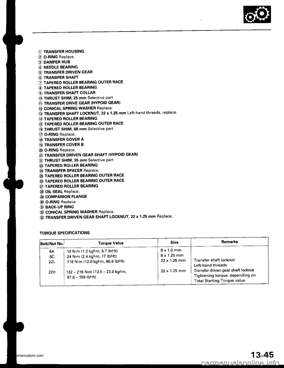
O TRANSFER HOUSING
@ O-RING Replace.
O DAMPER HUB
G) NEEDLE BEARING
G) TRANSFER DRIVEN GEAR
G) TRANSFER SHAFT
O TAPERED ROLLER BEARING OUTER RACE
@ TAPERED ROLLER BEARING
€) TRANSFER SHAFT COLLAR
@ THRUST SHIM, 25 mm selective part
6D TRANSFER DRIVE GEAR (HYPOID GEAR)
@ CONICAL SPRING WASHER RePlace
GD TRANSFER SHAFT LOCKNUT.22 x 1.25 mm Left-hand threads, replace'
E) TAPERED ROLLER BEARING
@ TAPERED ROLLER BEARING OUTER RACE
@ THRUST sHlM. 68 mm selective part
O o.RlNG Replace.
@ TRANSFER COVER A
GD TRANSFER COVER B
@ O-RING Replace.
€) TRANSFER DRIVEN GEAR SHAFT (HYPOID GEAR}
@ THRUST SHIM, 35 mm Selective Part
@ TAPERED ROLLER BEARING
@ TRANSFEB SPACEB RepIace.
@ TAPERED ROLLER BEARING OUTER RACE
@ TAPERED ROLLER BEARING OUTER RACE
@) TAPERED ROLLER BEARING
@ olL SEAL Replace.
@ COMPANION FLANGE
@ O-RING Replace.
@ BACK-UP RING
@ coNtcAL SPRING WASHEB Replace.
(o TRANSFER DRIVEN GEAR SHAFT LOCKNUT,22 x 1.25 mm Replace.
TOROUE SPECIFICATIONS
Boh/Nut No.Torque ValueSizeRemarks
6A
8C
22L
22H
12 N.m (1.2 kgf.m.8.7 lbf.ft)
24 N.m {2.4 kgf.m, 17 lbf'ft)
118 N.m (12.0 kgf.m, 86.8 lbf'ftl
132 - 216 N.m (13.5 - 22.0 kgf'm,
97.6 - 159 lbf.ft)
6x1.0mm
8 x 1.25 mm
22 x 1 ,25 mm
22 x 1 .25 mm
Transfer shaft locknut:
Lett-hand threads
Transfer driven gear shaft locknut
Tightening torque: dePending on
Total Starting Torque vaiue
13-45
www.emanualpro.com
Page 489 of 1395
Transfer Assembly
Transfer Shaft Disassembly/
Reassembly
1. Support the transfer driven gear on steel blocks,
then press the transfer shaft out of damper hub,
Align the damper hub grooves and transfer drivengear teeth, and reassemble the damper hub. needle
bearing, and transfer driven gear.
Install the transfer shaft using a press.
13-50
us Ing
Transfer Gover A Bearing Outer
Race Replacement
NOTE: Coat all parts with MTF during reassembly.
1. Bemove the tapered roller bearing outer race from
transfer cover A by heating the cover to almost212"F (100oC) using a heat gun. Do not heat thecover over 212"F (100'C),
2. Install the 68 mm thrust shim in transfer cover A.
TRANSFER COVER A
ATTACXMCNT,52x68mft07746 - tD,t0500
Install the tapered roller bearing outer race
the special tools and a press.
BEARING OUTER RACE
BEARING OUTER RACE
www.emanualpro.com
Page 503 of 1395

Mainshaft Thrust Clearance
Adjustment
l. Remove the 78 mm shim
the transmission housing.
4.
and oil guide plate from
Install the 3rd/4th synchro hub, spacer collar, sth
synchro hub, spacer, and ball bearing on the main-
shaft. then install the above assembly in the trans-
mission housing.
lnstallthe washer on the mainshaft.
Measure distance @ between the end of the trans-
mission housing and washer,
NOTE:
. Use a straight edge and vernier caliper.
. Measure at three locations and average the read-
Ing.
END otTRANSMISSION
MAINSHAFT
WASHER
3RD/4TH SYNCHRO HUB
SPACER COLLAR
sTH SYNCHRO HUB
SPACER
78 mm SHIM
13-64
BALL BEARING
5, Measure distance @ between the end of the clutch
housing and bearing inner race.
NOTE:
. Use a straight edge and depth gauge.
. Measure at three locations and avorage the read-
Ings.
END ot CLUTCH HOUSING
BEARING
Select the proper 78 mm shim from the chan by
using the formula below.
Shim S€lection Formula:
From the measurements you made in steps 4 and 5:-1. Add distance @ (step 5) to distance @ (step 4).
-2. From this number. subtract 0.93 (which is the
midpoint of the flex range of the clutch housing
bearing spring washer).
-3. Take this number and compare it to the avail-
able shim sizes in the chart.
(For example)
A: 2.39 2.61
+ Bi O.22 - 0.93
= 2.61= 1.68
Try the 1.68 mm (0.0661 in) shim.
www.emanualpro.com
Page 523 of 1395
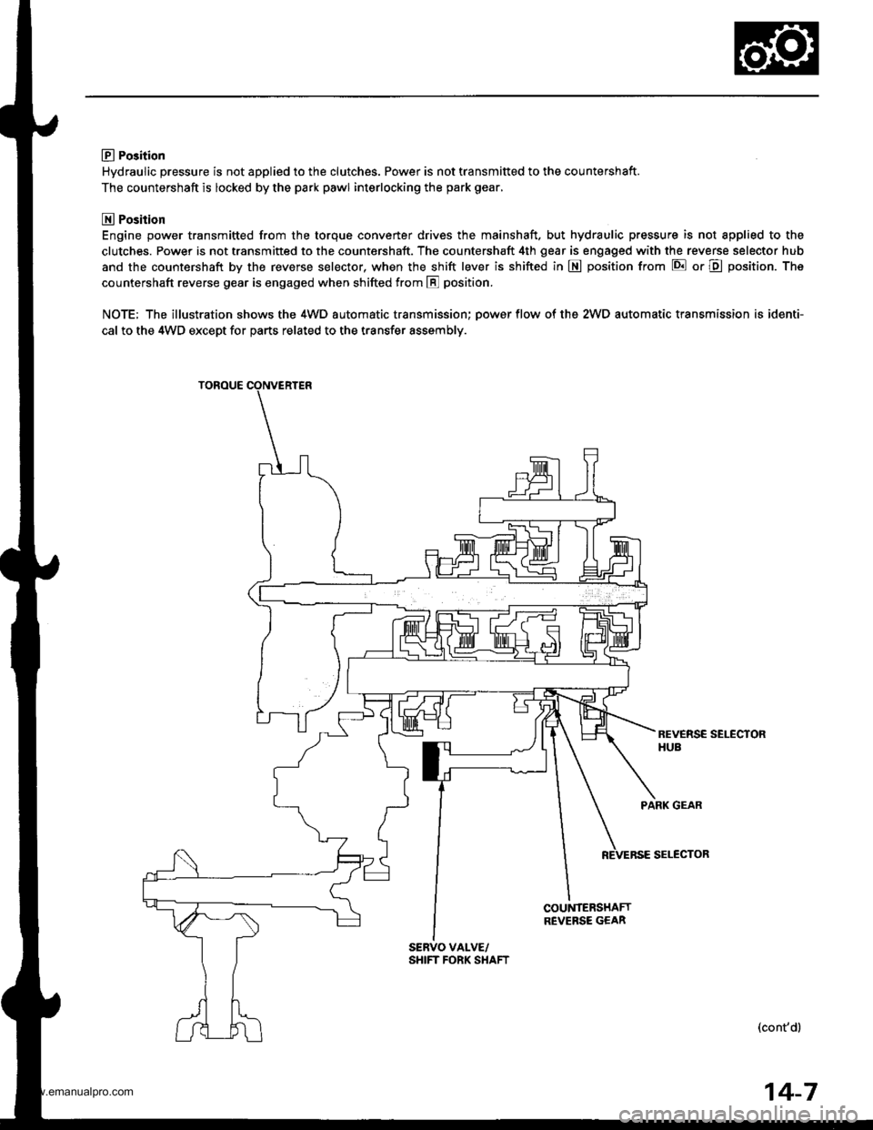
E Po3ition
Hydraulic pressure is not applied to the clutches. Power is not transmitted to the countershaft.
The countershaft is locked by the park pawl interlocking the park gear,
E Position
Engine power transmitted from the torque converter drives the mainshaft. but hydraulic pressure is not applied to the
clutches. Power is not transmitted to the countershaft. The countershaft 4th gear is engaged with the reverse selector hub
and the countershaft by the reverse selector, when the shift lever is shifted in E position from E or E position. The
countershaft reverse gear is engaged when shifted from E position.
NOTE; The illustration shows the 4WD automatic transmission; oower flow of the 2WD automatic transmission is identi-
cal to the 4WD exceDt for oarts related to the transfer assemblv.
PARK GEAR
SELECTOR
(cont'd)
COUNTERSHAFTREVEBSE GEAR
14-7
www.emanualpro.com