1998 HONDA CR-V troubleshoot
[x] Cancel search: troubleshootPage 1313 of 1395
Gomponent/Wiring Locations Index -'98 - 00 models
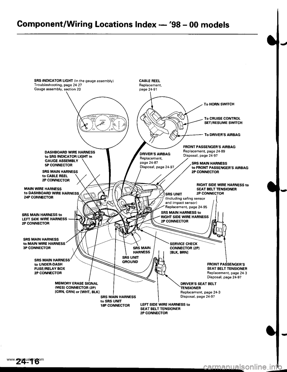
SRS INDICAIOR LIcHT (ln the gauge assembty)Troubleshooting, page 24 27Gauge assembly. section 23
DASHBOARD WIRE HARNESSto SRS INDICATOR LIGHf inGAUGE ASSEMBLY5P CONNECTOR
FRONT PASSENGER'S AIRBAGReplacement, page 24-89Disposal, page 24 97
CABLE REELReplacement,page 24-91
To HORN SWITCH
To CRUISE CONTROLSET/RESUME SWTCH
To DRIVER'S AIRBAG
ro CABLE REEL2P CONNECTOR
MAIN VYIRE HARNESSto DASHBOARD WIRE HARNESS
SRS MAIN HARNESS
ORIVER'S AIRBAGReplacement,page 24-87Disposal, page 24-97
SRS UNIT
SRS MAIN HARNESSto FROI{T PASSENGER,S AIRBAG2P CONiIECTOR
RIGHT SIDE WIRE HARNESS toSEAI BELTTENSIONER2P CONNECTOR24P CONNECTOR
SRS MAIN
SRS MAIN HARNESS toLEFT SIDE WIRE HARNESS2P CONNECTOR
SRS MAIN HARNESSto MAIN WIRE HARNESS3P CONNECTOB
(lncluding safing sensorand impact sensor)Replacement, page 24-95
SRS MAIN HARNESS toRIGHT SIDE WIRE HARNESS2P CONNECTOR
SERVICE CHECKCONNECTOR I2PIIBLK BRNI
to UNDER-DASHFUSE/RELAY BOX2P CONNECTORSEAT BELT TENSIONERReplacement, page 24 3Disposal, page 24-97
ORIVER'S SEAT BELTMEMORY ERASE SIGNAL(MES) CONNECTOR I2PIIGRN, GRNI or IWHT, BLKIReplacement, page 24-3Disposal, page 24-97
LEFT SIDE WIRE HARNESS toSEAT BELTTENSIONER2P CONNECTOR
24-16
.4
www.emanualpro.com
Page 1317 of 1395
Precautions/Procedures
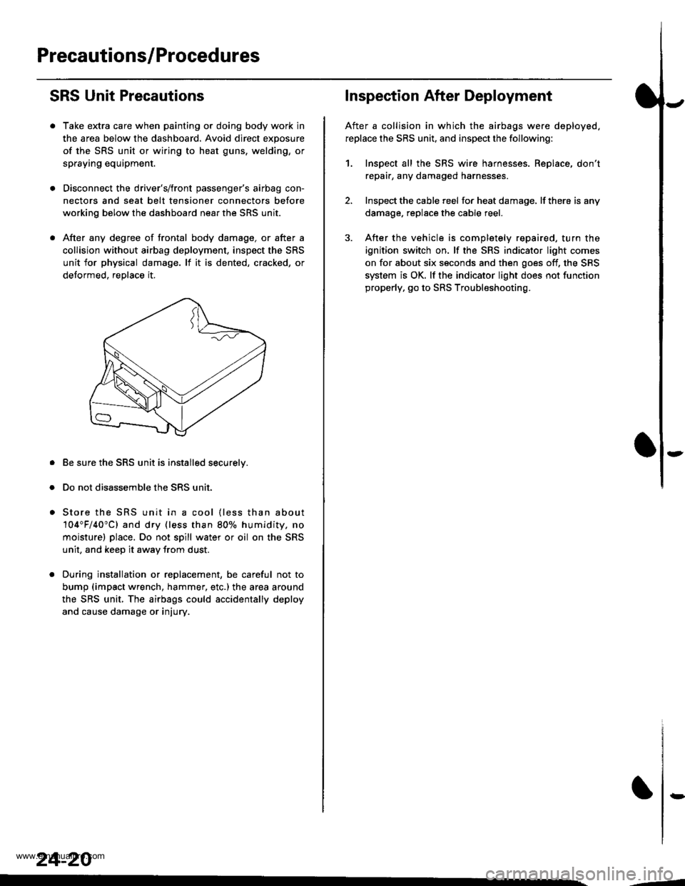
SRS Unit Precautions
Take extra care when painting or doing body work in
the area below the dashboard. Avoid direct exposure
of the SRS unit or wiring to heat guns, welding, or
spraying equipment.
Disconnect the driver's/front passenger's airbag con-
nectors and seat belt tensioner connectors before
working below the dashboard near the SRS unit.
After any degree of frontal body damage, or after a
collision without airbag deployment, inspect the SRS
unit for physical damage. lf it is dented, cracked, or
detormed, reolace it,
Be sure the SRS unit is installed securelv.
Do not disassemble the SRS unit.
Store the SRS unit in a cool {less than about
104"F/40"C) and dry {less than 80o/o humidity. no
moisture) place. Do not spill water or oil on the SRS
unit, and keep it awav from dust.
During installation or replacement, be careful not to
bump (impact wrench, hammer, etc.) the area a[ound
the SRS unit, The airbags could accidentally deploy
and cause damage or injury.
24-20
,..4
Inspection After Deployment
After a collision in which the airbags were deployed.
replace the SRS unit, and inspect the following:
1. Inspect all the SRS wire harnesses. Replace, don't
repair, any damaged harnesses
2. Inspect the cable reel for heat damage, lf there is any
damage. replace the cable reel.
3. After the vehicle is completely repaired, turn the
ignition switch on. lf the SRS indicator light comes
on for about six seconds and then goes off, the SRS
system is OK. lf the indicator light does not function
properly, go to SRS Troubleshooting.
rD
www.emanualpro.com
Page 1323 of 1395
Troubleshooting
Self-diagnostic Procedures
The self-diagnostic function of the SRS system allows it to locate the causes of system problems and to store this informa-
tion in memory, For easier troubleshooting, this data can be retrieved via a data link circuit.
. When you turn the ignition switch ON (ll). the SRS indicator will come on. lf it goes off after six seconds, the system is
normal.
. lf there is 8n abnormality, the system locates and defines the problem. stores this information in memory, and turns
the SRS indicator light on. The data will remain in the memory even when the ignition switch is turned off or if the bat-
terv is disconnected.
. When you connect the SCS service connector to the service check connector (2P), and turn the ignition switch ON (ll),
the SRS indicator light will indicate the diagnostic trouble code (DTC) by the number of blinks.
. After reading and recording the DTC, proceed with the troubleshooting forthis code.
Precsutions
. Use only a digital multimeter to check the system. lf it's not a Honda multimeter. make sure its output is 10 mA (0.01 A)
or less when switched to the smallest value in the ohmmeter range. A tester with a higher output could damage the
airbag circuit or cause accidental airbag deployment and possible injury.
. Whenever the ignition switch isON (ll). or has been turned OFF for less than three minutes, be careful nottobumpthe
SRS unit; the airbags could accidentally deploy and cause damage or injuries.
. Before you remove the SRS main harness, disconnect the airbag and tensioner connectors (see page 24-23).
. Make sure the battery is sufficiently charged (see section 23). lf the battery is dead or low, measuring values won't be
correct.
. Do not touch a tester probe to the terminals in the SRS unit or harness connectors, and do not connect the terminals
with a jumper wire. Use only the backprobe set and the SCS service connector.
For backprobing spring-loaded lock type con nectors, .efet to page 24-22.
Reading the DTC
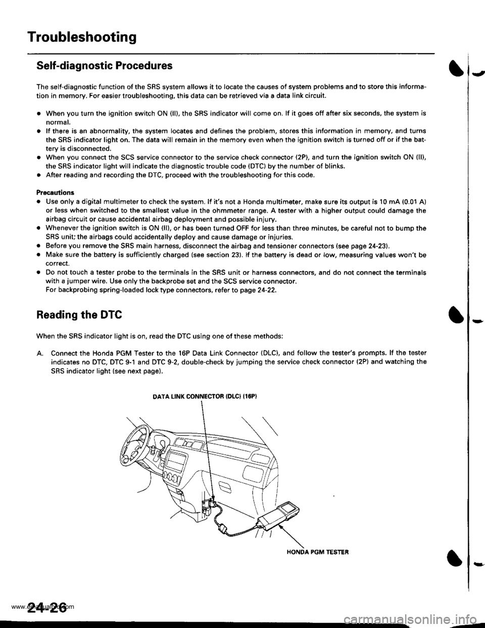
When the SRS indicator light is on, read the DTC using one of these methods;
A. Connect the Honda PGM Tester to the 16P Data Link Connector {DLC), and follow the tester's prompts. lf the tester
indicates no DTC, DTC 9-1 and DTC 9-2, double-check by jumping the service check connector (2P) and watching the
SRS indicator light (see next page).
HONDA PGM TESTER
DATA LINK CONNECIOR {DLCI {16P)
24-26
,1
www.emanualpro.com
Page 1325 of 1395
Troubleshooting
Erasing the DTC Memory
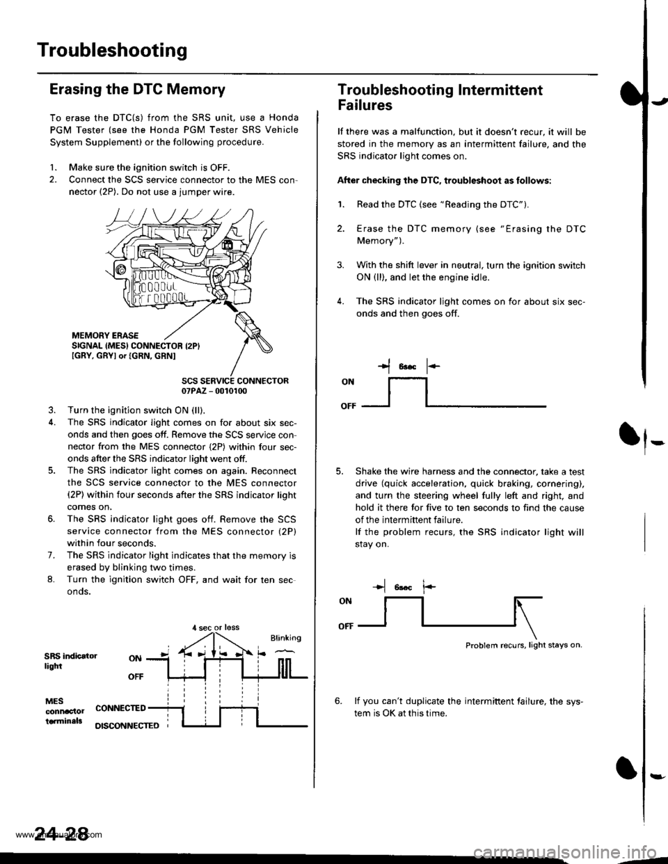
To erase the DTC{S) from the SRS unit, use a Honda
PGM Tester (see the Honda PGM Tester SRS Vehicle
System Supplement) or the following procedure.
1. Make sure the ignition switch is OFF.
2. Connect the SCS service connector to the MES con,
nector (2P). Do not use a jumper wire.
MEMORY ERASESIGNAL (MES} CONNECTOR I2PIIGRY, GRYI or IGRN, GRNI
SCS SERVICE CONNECTOR07PAZ - 0010100
3. Turn the ignition switch ON (ll),
4. The SRS indicator light comes on for about six sec-
onds and then goes off. Remove the SCS servjce con
nector from the MES connector {2P) within four sec-
onds after the SRS indicator light went otf.
5. The SRS indicator light comes on again. Reconnect
the SCS service connector to the MES connector(2P) within four seconds after the SRS indicator lioht
comes on,
6. The SRS indicator light goes otf. Remove the SCS
service connector from the MES connector (2P)
within four seconds.
7. The SRS indicator light indicates that the memory is
erased by blinking two times.
L Turn the ignition switch OFF, and wait for ten sec
onos.
SRS indicatorliqtfi
MESconnac'lolterminals
OFF
CONNECTED
OISCONNECTEO
24-28
,l sec or less
3.
Troubleshooting Intermittent
Failures
lf there was a malfunction. but it doesn't recur, it will be
stored in the memory as an intermittent failure, and the
SRS indicator light comes on.
After checking the DTC, troubleshoot as follows:
1. Read the DTC (see "Reading the DTC").
4.
Erase the DTC memory (see "Erasing the DTC
Memory").
With the shift lever in neutral, turn the ignition switch
ON (ll), and let the engine idle.
The SRS indicator ljght comes on for about six sec-
onds and then goes off.
t*F
ON
lt--- _l
Shake the wire harness and the connector, take a test
drive (quick acceleration, quick braking, cornering),
and turn the steering wheel fully left and right, and
hold it there for five to ten seconds to find the cause
of the intermittent failure.
lf the problem recurs, the SRS indicator light will
stay on.
-+t 6!.c l.-
Problem recurs, light stays on.
6. lf you can't duplicate the intermiftent tailure, the sys-
tem is OK at this time.
:-
-4
www.emanualpro.com
Page 1326 of 1395
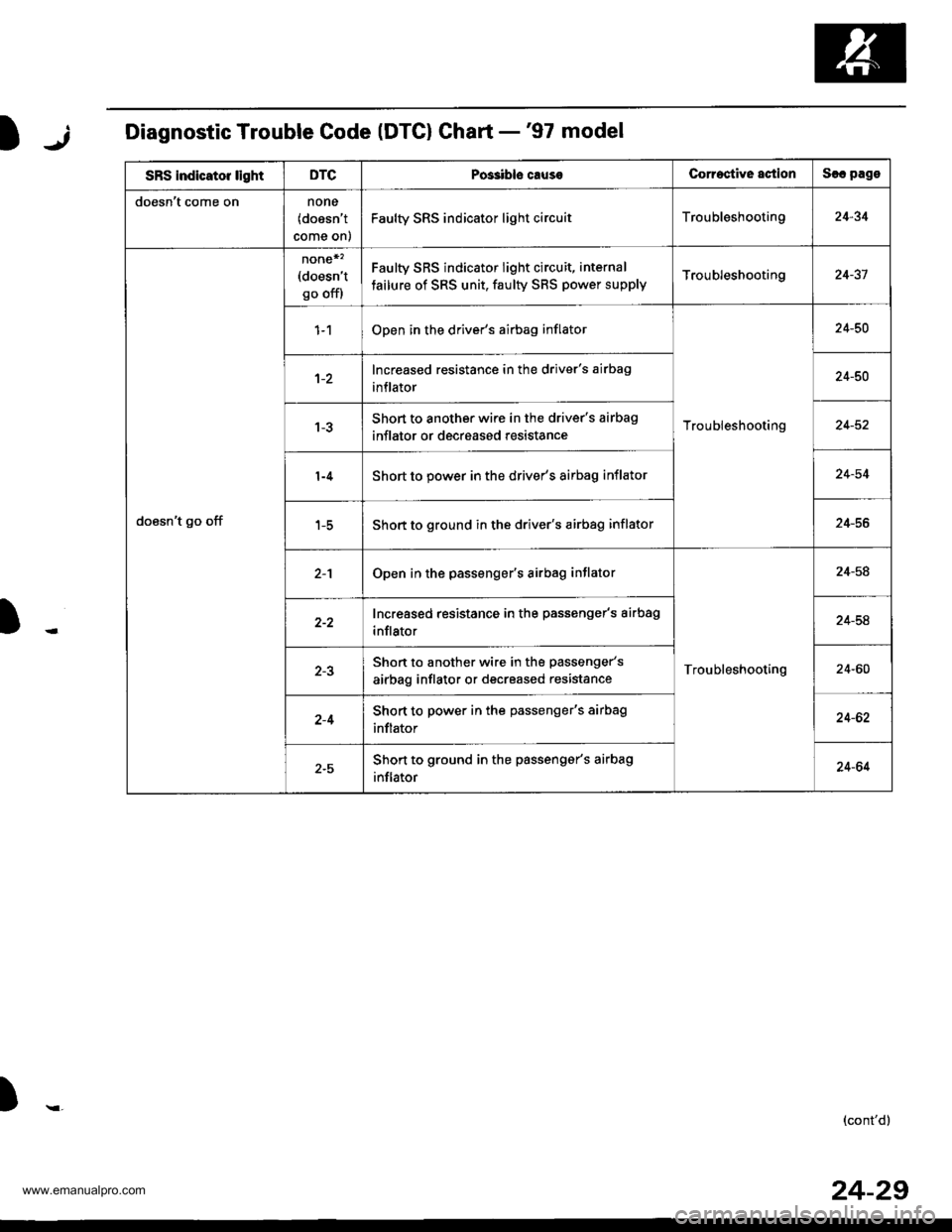
jIDiagnostic Trouble Code (DTG) Ghart -'97 model
SRS indicator lightDTCPos3ibls causeCorroctive actionSlc pago
doesn't come onnone(doesn't
come on)
Faulty SRS indicator light circuitTroubleshooting24-34
doesn't go off
none*'�(doesn't
go off)
Faulty SRS indicator light circuit, internal
tailure of SRS unit, faulty SBS power supplyTroubleshooting24-37
Open in the driver's airbag inflator
Troubleshooting
24-50
Increased resistance in the driver's airbag
inflator24-50
Short to another wire in the driver's airbag
inflator or decreased resistance24-52
Short to power in the driver's airbag inflator24-54
Short to ground in the driver's airbag inflator24-56
Open in the passenger's airbag inflator
Troubleshooting
24-58
Increased resistance in the passenger's airbag
inflator24-54
Shon to another wire in the passenger's
airbag inflator or decreased resistance24-60
2-4Short to power in the passenger's airbag
inflator24-62
2-5Shon to ground in the passengar's airbag
inflator24-64
)r,(cont'd)
24-29
www.emanualpro.com
Page 1327 of 1395
Troubleshooting
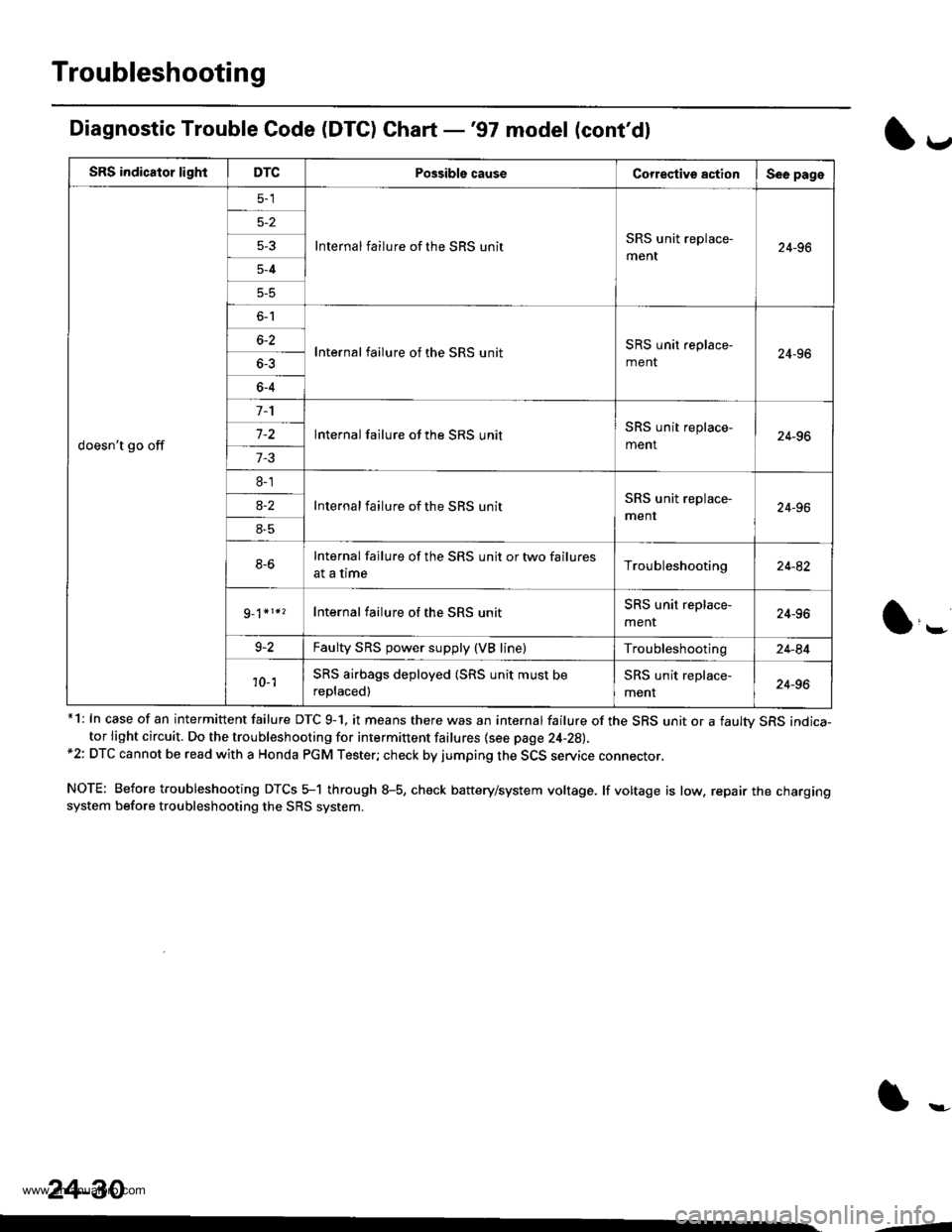
Diagnostic Trouble Code (DTC) Chart -'97 model (cont'dl
*1: In case of an intermittent failure DTC 9-1, it means there was an internal failure of the SRS unit or a faultv SRS indica-tor light circuit. Do the troubleshooting for intermittent failures {see page 24-28),*2: DTC cannot be read with a Honda PGM Tester; check by jumping the SCS service connector.
NOTE: Before troubleshooting DTCS 5-1 through 8-5, check battery/system voltage. lf voltage is low. repair the chargingsystem before troubleshooting the SRS system.
l*
SRS indicator lightDTCPossible causeCorrestive actionSee page
doesn't go off
Internal failure of the SRS unitSRS unit replace-
ment24-965-3
5-4
5-5
o-l
Internal failure of the SRS unitSRS unit replace-
ment24-966-2
6-4
lnternal failure of the SRS unitSRS unit replace-
ment24-967-2
7-3
8-1
Internal failure of the SBS unitSRS unit replace-
menr24-96a-2
8-5
8-6Internal failure of the SRS unit or two failures
at a timeTroubleshooting24-82
Internal failure of the SRS unitSRS unit replace-
menr24-96
9-2Faulty SRS power supply (VB line)Troubleshooting24-84
'10- 1SRS airbags deployed (SRS unit must be
replaced)
SRS unit replace-
ment24-96
24-30
--
www.emanualpro.com
Page 1328 of 1395
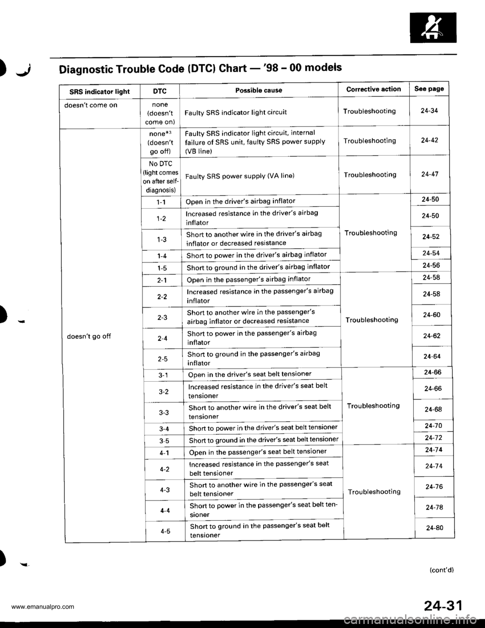
);Diagnostic Trouble Code (DTCI Chart -'98 - 00 models
SRS indicator lightDTCPossibls causeCorrectiva agtionSee page
doesn t come onnone
(doesn't
come on)
Faulty SRS indicator light circuitTroubleshooting24-34
doesn't go off
none*3
{doesn'tgo off)
No DTC
(light comes
on after self-
diagnosis)
Faulty SRS indicator light circuit. internal
failure of SRS unit, faulty SRS power supply
(VB line)
Troubleshooting24-42
Faulty SRS power supply (VA line)Troubleshooting24-47
1-1Open in the driver's airbag inflator
Troubleshooting
24-50
lncreased resistance in the driver's airbag
inflator24-50
1-3Short to another wire in the driver's airbag
inflator or decreased reslstance24-52
1-4Short to power in the driver's airbag inflator24-54
1-5Short to ground in the driver's airbag inflator24-56
2-1Open in the passenger's airbag inflator
Troubleshooting
24-54
Increased resistance in the passenger's airbag
inflator24-58
Shon to another wire in the passenger's
airbag inflator or decreased resistance24-60
2,4Short to power in the passenger's airbag
inflator24-62
Short to ground in the passenger's arrbag
inflator24-64
3-1Open in the driver's seat belt tensioner
Troubleshooting
24-66
3-2lncreased resistance in the driver's seat belt
tensroner24-66
Shon to another wire in the driver's seat belt
tensroner24-64
3-4Short to power in the driver's seat belt tensioner24-10
Short to ground in the driver's seat belt tensloner24-7 2
4-1Open in the passenger's seat belt tensioner
Troubleshooting
24-14
Increased resistance in the passenger's seat
belt tensioner24-7 4
4-3Short to another wire in the passenger's seat
belt tensioner24-7 6
4-4
4-5
Short to power in the passenger's seat belt ten-
sroner24-74
Shon to ground in the passenger's seat belt
tensroner24-AO
)-(cont'd)
24-31
www.emanualpro.com
Page 1329 of 1395
Troubleshooting
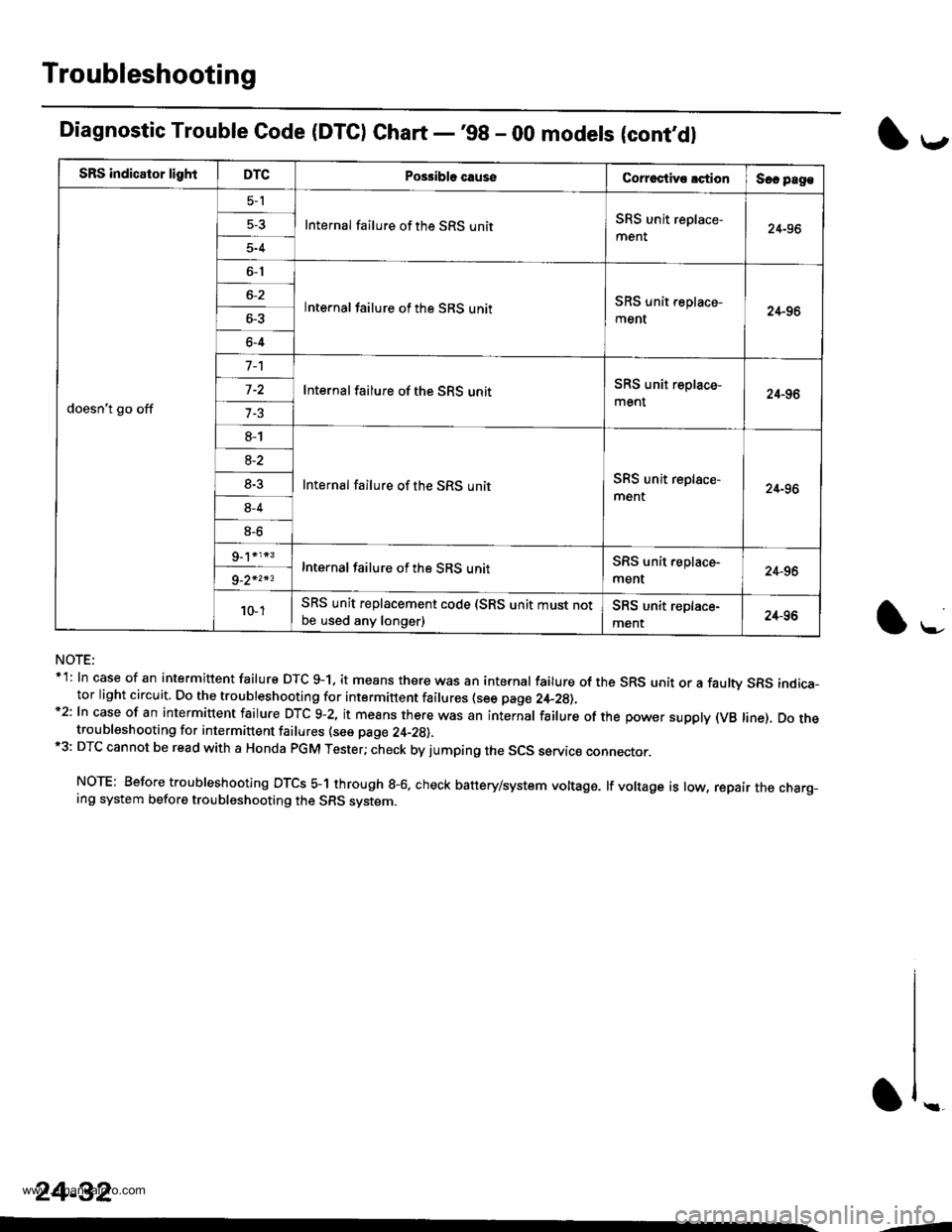
SRS indicator lightDTCPo$ibla causeCorroctive lctionSec pag€
doesn't go off
5-l
Internal failure of the SRS unitSRS unit replace-
ment24-96
5-4
6-1
lnternal failure of the SRS unitSRS unit replace-
ment24-966-3
6-4
Internal failure of the SRS unitSRS unit replace-
ment24-96
8-1
Internal failure of the SRS unitSRS unit replace-
ment24-96
8-2
8-3
8-4
8-6
Internal failure of the SRS unitSRS unit.eplace-
ment24-969_2*2*3
10- 1SRS unit replacement code (SRS unit must notbe used any longer)SRS unit replace-
ment24-96
Diagnostic Trouble Code (DTC) Chart -'98 - 00 modets (cont,dl
NOTE:*1: In case of an intermittent failure DTC g-1, it means there was an internal failure of the SRS unit or a faulw SRS indica-tor light circuit. Do the troubleshooting for intermittent failures (see page 2,+_2g),*2: In case of an intermiuent fairure DTc 9-2, it means there was an internar fairure of the power suppry (vB rine). Do thetroubleshooting for intermittent failures (see page 24-29).*3: DTC cannot be read with a Honda PGM Tester; check by jumping the SCS servic€ connector.
NOTE: Before troubleshooting DTCS 5-1 through g-6. check battery/system voltage. lf voltage is low, repair the charg_ing system before troubleshooting the SRS system.
l*-
1,.-
\f ..
24-32
--
www.emanualpro.com