1998 HONDA CR-V light
[x] Cancel search: lightPage 933 of 1395
Front Brake Pads
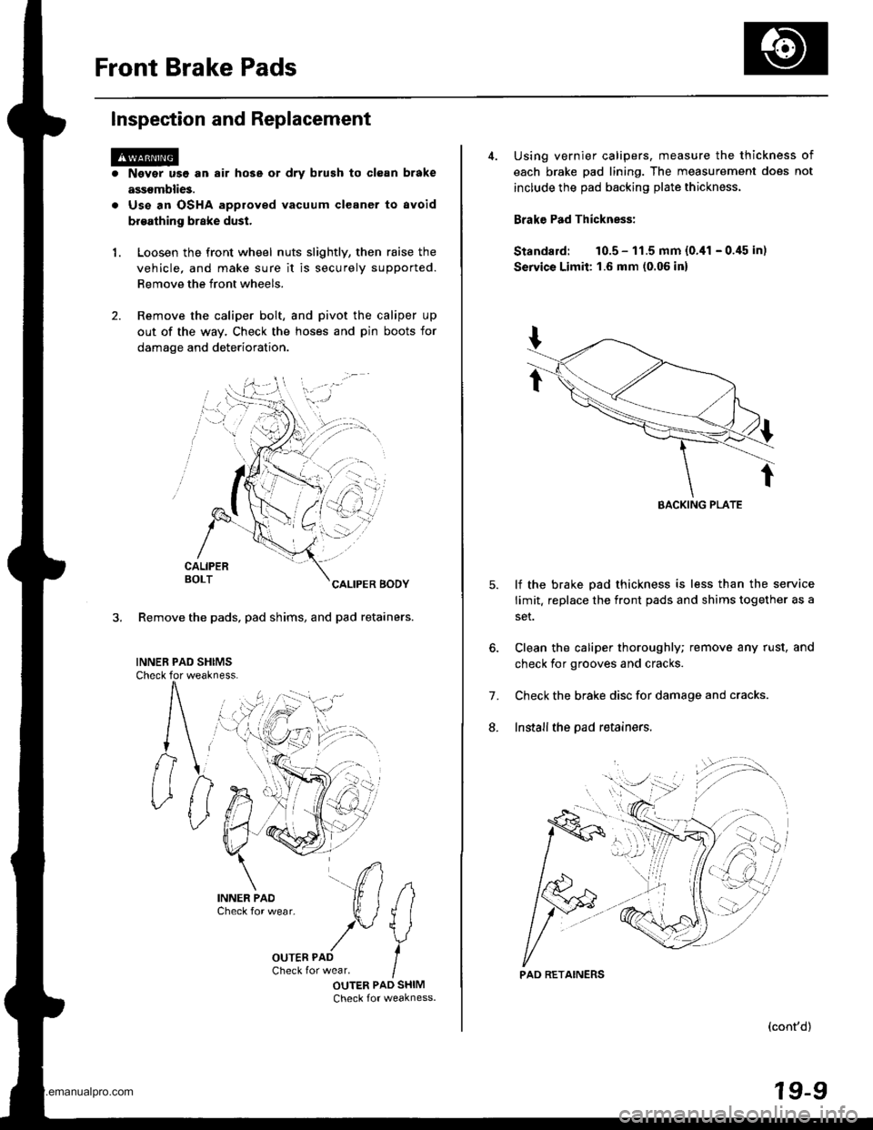
Inspection and Replacement
1.
Nsvgr u9e an air hose or dry brush to clean brake
assemblies.
Use an OSHA approved vacuum cleaner to avoid
broathing brake dust.
Loosen the front wheel nuts slightly, then raise the
vehicle, and make sure it is securely supported.
Remove the front wheels.
Remove the caliper bolt, and pivot the caliper up
out of the way. Check the hoses and pin boots for
damage and deterioration.
CALIPERBOLTCALIPER BODY
3. Remove the pads, pad shims, and pad retainers.
INNEB PAD SHIMSCheck for weakness.
#
IOUTER PAD SHIMCheck for weakness.
i)n.
4. Using vernier calipers, measure the thickness of
each brake pad lining. The measurement does not
include the pad backing plate thickness.
Brake Pad Thickness:
Standard: 10.5 - 11.5 mm {0.,11 - 0.45 in)
Servics Limit: 1.6 mm (0.06 in)
lf the brake pad thickness is less than the service
limit. replace the front pads and shims together as a
set.
Clean the caliper thoroughly; remove any rust, and
check for grooves and cracks.
Check the brake disc for damage and cracks.
Install the pad retainers.
7.
L
(cont'd)
19-9
EACKING PLATE
'.'..i
PAD RETAINERS
www.emanualpro.com
Page 935 of 1395
Front Brake Disc
Disc Runout Inspection
l.Loosen the front wheel nuts slightly, then raise the
vehicle, and make sure it is securely supported.
Remove the front wheels.
Remove the brake pads {see page 19-9).
Inspect the disc surface for damage and cracks.
Clean the disc thoroughly, and remove all .ust.
Use wheel nuts and suitable plain washers to hold
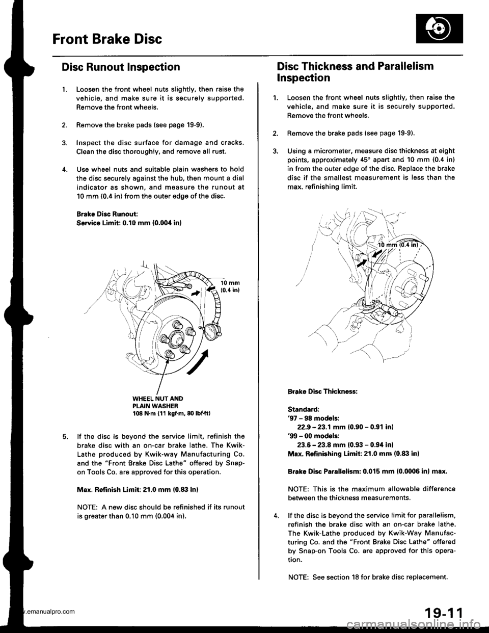
the disc securely against the hub, then mount a dial
indicator as shown, and maasure the runout at
10 mm (0.4 in) from the outer edge of the disc.
Brake Di3c Runout:
Service Limit: 0.10 mm {0.00,0 in)
WHEEL NUT ANDPLAIN WASHER108 N.m {11 kg{ m, 80 lbf.ft)
lf the disc is beyond the service limit, refinish the
brake disc with an on-car brake lathe. The Kwik-
Lathe produced by Kwik-way Manufacturing Co.
and the "Front Brake Disc Lathe" offered by Snap-
on Tools Co. are approved for this operation.
M8x. Rofinish Limit: 21.0 mm l0.8il in)
NOTE: A new disc should bs refinished if its runout
is greater than 0.10 mm (0.004 in).
Disc Thickness and Parallelism
Inspection
1.Loosen the front wheel nuts slightly, then raise the
vehicle, and make sure it is securely supported.
Remove the front wheels.
Remove the brake pads (see page 19-9).
Using a micromater, measure disc thickness at eight
points, approximately 45'apan and 10 mm (0.4 in)
in from the outer edge of the disc. Replace the brake
disc if the smallest measurement is less than the
max. refinishing limit.
Brake Disc Thickness:
Standard:'97 - 98 modsls:
22.9 -23.1mm {0.90 - 0.91 inl'99 - 00 mod€ls:
23.6 - 23.8 mm {0.93 - 0.94 in}
Max. Refinishing Limit:21.0 mm (o.txl in)
Brake Disc Parallelism: 0.015 mm {0.0006 in} max.
NOTE: This is the maximum allowable difference
between the thickness measurements,
lf the disc is beyond the service limit for parallelism,
refinish the brake disc with an on-car brake lathe.
The Kwik-Lathe produced by Kwik-Way Manufac-
turing Co. and the "Front Brake Disc Lathe" offered
by Snap-on Tools Co. are approved for this opera-
tron.
NOTE: See section 18 for brake disc replacement.
19-1 1
www.emanualpro.com
Page 939 of 1395

6.
7.
8.
lf the clearance between the gauge body and
adjusting nut is 0.4 mm (0.02 in), the pushrod-to-
piston clearance is 0 mm. However. if the clearance
between the gauge body and adjusting nut is 0 mm,
the pushrod-to-piston clearance is 0.4 mm (0.02 in)
or more. Therefore it must be adjusted and
recheck€d.
lf clearance is incorrect, loosen the star locknut, and
turn the adjuster in or out to adjust.
. Adjust the clearance while the specified vacuum
is applied to the booster.
. Hold the clevis while adjusting.
Tighten the star locknut securely.
Remove the special tool.
0 - 0.4 mm (0 - 0.02 inl
Adjust the pushrod length as shown if the
is removed,
booster
11610.5 mm{4.6 t 0.02 inl
PUSHRODLOCKNUT1.5N.m 11.5 kgf.m. '11 lbtfl)
Install the master cylinder (see page 19-13).
9.
STAR LOCKNUT22 N.m12.2 kgt m. 16 lbtftl
10.
(Check valve is built-in)
Brake Booster Inspection
FunctionalTest
1. With the engine stopped, press the brake pedal sev-
eral times to deplete the vacuum reservoir. thenpress the pedal hard, and hold it for 15 seconds. lf
the pedal sinks, either the master cylinder is
bypassing internally, or the brake system (master
cylinder, lines, modulator, proportioning valve. or
caliper) is leaking.
2. Start the engine with the pedal pressed. lf the pedal
sinks slightly. the vacuum booster is operating nor-
mally. lf the pedal height does not vary, the booster
or check valve is faultv.
3. With the engine running, press the brake pedal light-
ly. Apply just enough pressure to hold back auto-
matic transmission creep. lf the brake pedal sinks
more than 10 mm (3/8 in.) in three minutes, the mas-
ter cylinder is faulty. A slight change in pedal height
when the Ay'C compressor cycles on and off is nor-
mal. (The Ay'C compressor load changes the vacuum
available to the booster.)
Leak Test
1.Press the brake pedal with the engine running, then
stop the engine. lf the pedal height does not vary
while pressed for 30 seconds, the vacuum booster is
OK. lf the pedal rises, the booster is faulty.
With the engine stopped, press the brake pedal sev-
eral times using normal pressure. When the pedal is
first pressed. it should be low, On consecutive appli-
cations, the pedal height should gradually rise. lf thepedal position does not vary. check the booster
check valve.
Boostor Chock Valve Test
1. Disconnect the brake booster vacuum hose at the
booster.
2. Start the engine, and let it idle. There should be vac-
uum. lf no vacuum is available, the check valve is
not working properly. Replace the brake booster
vacuum hose and check valve. and retest.
ERAKE BOOSTERVACUUM HOSE
www.emanualpro.com
Page 940 of 1395
Rear Drum Brakes
Never use an air hose or dry brush to clgan brake assemblies,
Use an OSHA approved vacuum cleaner to avoid breathing brake dust.
Contaminated brake linings or drums reduce stopping ability.
Block the front wheels betore iacking up lhe rear ot the vehicle,
Block the front wheels, loosen the rear wheel nuts slightly, then raise the
poned. Remove the rear wheels.
2. Release the parking brake, and remove the rear brake drum.
I N.m {0.9rbr.ft)kgl.m,5.5
\\
\
196
@
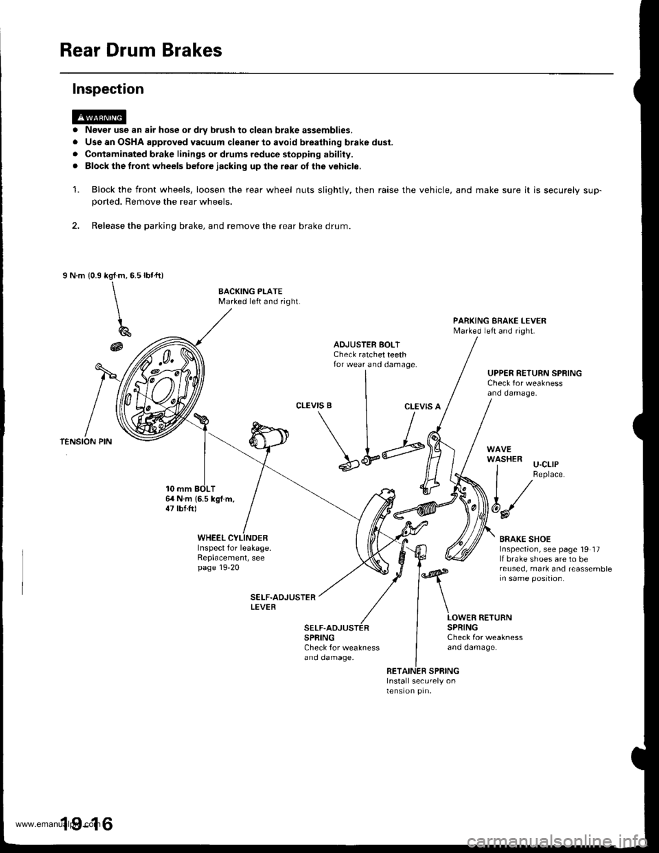
Inspection
a
a
rl
a
1.vehicle, and make sure it is securely sup-
BACKING PLATEMarked left and right.
PARKING EBAKE I-EVERMarked left and right.
ADJUSTER BOLTCheck ratchet teethfor wear and damage.UPPER RETURN SPRINGCheck for weaknessand damage.
CLEVIS BCLEVIS A
64 N.m 16.5 kgl.m,47 lbt.ftl
\L;
SPRINGCheck for weaknessano oamage.
'l-'-' u-cllP
I Replace.
t/
6d/
BRAKE SHOEInspection, see page 19 17lf brake shoes are to bereused, mark and reassemblein same position.
WHEELInspect for leakage.Replacement, seepage 19-20
LOWER RETURNSPRINGCheck for weaknessano oamage.
RETAINER SPRINGInstall securely onlensron prn.
19-16
www.emanualpro.com
Page 948 of 1395

Anti-lock Brake System (ABSI,'97 - 00 Models
Special Tools ............. 19-26
Component Locations ......................... 19-27
Anti-lock Brake System (ABS)
Features/Construction ............. ......, 19-2A
Circuit Diagram ......... 19-32
ABS Control Unit Terminal
Arrangement ......... 19-34
Troubleshooting Precautions ............. 19-36
Diagnostic Trouble Gode (DTC)
Diagnostic Trouble Code (DTC)
Indication (SCS Model ................ 19-38
DTG Erasure (MES Mode) ............... 19-39
Troubleshooting lndex .................... 19-40
Troubleshooting
ABS Indicator Light Does Not
Come On ............ 19-41
ABS Indicator Light Does Not
Go Off (No DTC) ........................... 19-43
DTC 1r - 18:
Wheel Sensor .... 19-45
DTC 31 - 38:
Solenoid ............. 19-47
DTC 51 - 53:
ABS Pump Motor ......................... 19-49
DTC 54:
Main Relay ......... 19-52
DTC 61:
lgnition Voltage ........................... 19-54
DTC 81:
Central Processing Unit (CPU) .... 19-55
Modulator Unit
Removal/lnstallation ....................... 19-56
ABS Control Unit
Replacement ..,...... 19-57
Pulsers/Wheel Sensors
Inspection .............. 19-57
Wheel Sensor Replacement ............ 19-58
www.emanualpro.com
Page 952 of 1395

ABS Control
The ABS control unit detects the wheel speed based on the wheel sensor signal it received, then it calculates the vehicle
speed based on the detected wheel speed. The control unit detects the vehicle speed during deceleration based on the
rate of deceleration.
The ABS control unit calculates the slip rate of each wheel, and it transmits the control signal to the modulator unit
solenoid valve when the slip rate is high
The pressure reduction control has three modes: pressure reducing, pressure retaining, and pressure intensi{ying modes.
Self-diagnosis Function
The ABS control unit is equipped with a main cPU and a sub cPU, that check each other for problems.
The CPUs check the circuit of the system.
When the CPUS detect failure, they shift to the "system down mode" or the "control inhibition mode".
The self-diagnosis can be classitied into these four categories:
O: Initial diagnosis
O: Except ABS control
O; During ABS control
@: During warning
On-board Diagnosis Function
The ABS system can be diagnosed with the Honda PGM Tester.
The ALB Checker cannot be used with this system. For air bleeding. and checking wheel sensor signals, use the Honda
PGIM Tester. See the Honda PGM Tester user's manuals for specific operating instructions.
(cont'd)
19-29
ABS CONTROL I-INIT
MODEABSINDICATOR LIGHTMAIN
RE LAY
SOLENOID
VALVERestan conditionDTC
SYSTEM
DOWNONNo
operatron
Drive
inhibitionOperation*rlgnition
switchOFF - oN (ll)Memory
CONTROL
INHIBITIONONNo
operaton
Drive
inhibitionOperationAutomaticlVemory
*1: Except CPU failure
www.emanualpro.com
Page 1005 of 1395
Doors
(cont'd)
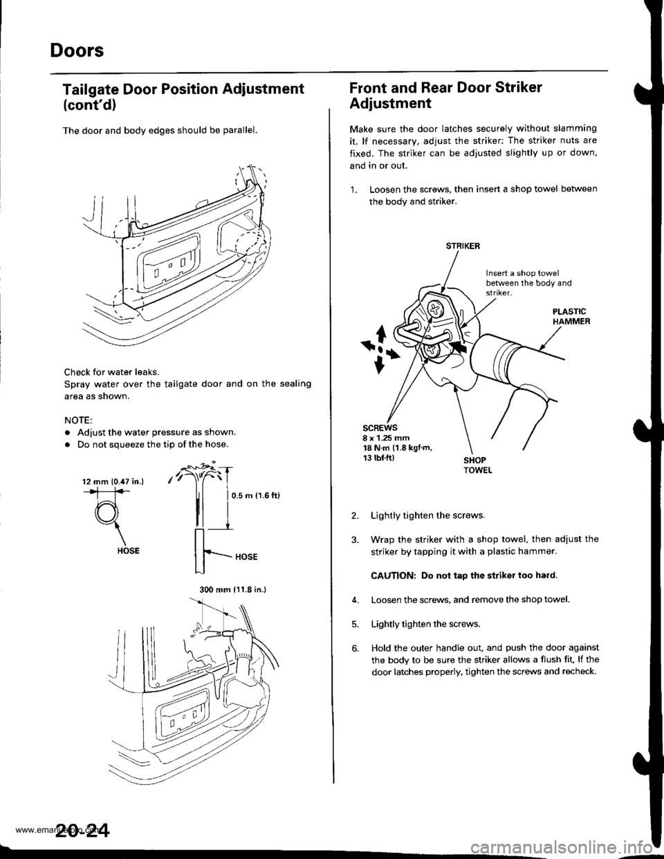
The door and body edges should be parallel.
Check for water leaks.
Spray water over the tailgate door and on the sealing
area as shown.
NOTE:
. Adjust the water pressure as shown.
. Do not squeeze the tip ofthe hose.
Tailgate Door Position Adiustment
-€*4
,'r)"C
II
0.5 m {1.6 ft}
20-24
l2 mm (0.47 in.).*1:]*
d3"1
HOSE
300 mm {11.8 in.l
Front and Rear Door Striker
Adjustment
Make sure the door latches securely without slamming
it, lf necessary, adjust the striker: The striker nuts are
fixed. The striker can be adjusted slightly up or down,
and in or out.
1. Loosen the screws, then insert a shop towel between
the body and striker.
Insert a shop towelbetween the body and
scREws8 x 1 .25 mm18 N.m (1.8 kgt.m,13 rbf.ft)
2.
J.
Lightly tighten the screws.
Wrap the striker with a shop towel, then adjust the
striker by tapping it with a plastic hammer.
CAUTION: Do not tap the striksr loo hard.
Loosen the screws. and remove the shop towel.
Lightly tighten the screws.
Hold the outer handle out, and push the door against
the body to be sure the striker allows a flush fit, lf the
door latches properly. tighten the screws and recheck.
4.
5.
6.
STRIKER
www.emanualpro.com
Page 1006 of 1395
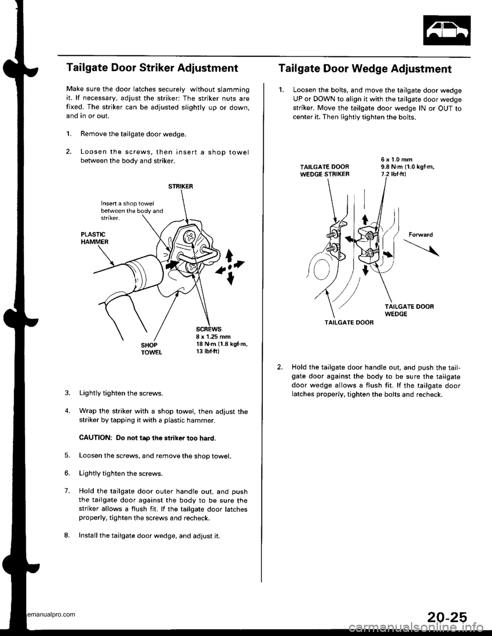
Tailgate Door Striker Adjustment
Make sure the door latches securely without slamming
it. lf necessary, adjust the striker: The striker nuts are
fixed. The striker can be adjusted slightly up or down,
and in or out.
1. Remove the tailgate door wedge.
2. Loosen the screws, then insert a shop towel
between the body and striker.
8 x 1.25 mm18 N.m (1.8 kgf.m,r 3 tbf.ft)
1.
4.
Lightly tighten the screws.
Wrap the striker with a shop towel, then adjust the
striker by tapping it with a plastic hammer.
CAUTION: Do not tap the striker too hard.
Loosen lhe screws, and remove the shop towel.
Lightly tighten the screws.
Hold the tailgate door outer handle out, and push
the tailgate door against the body to be sure thestriker allows a flush fit. lf the tailgate door latchesproperly, tighten the screws and recheck.
Install the tailgate door wedge, and adjust it.
STRIKER
Insen a shoptowelbetween the body and
Tailgate Door Wedge Adjustment
1. Loosen the bolts, and move the tailgate door wedge
UP or DOWN to align it with the tailgate door wedge
striker. Move the tailgate door wedge lN or OUT to
center it. Then lightly tighten the bolts.
TAILGATE OOOR
Hold the tailgate door handle out, and push the tail-gate door against the body to be sure the tailgate
door wedge allows a flush fit. lf the tailgate door
latches properly, tighten the bolts and recheck.
Forward
20-25
www.emanualpro.com