Page 874 of 1395

8.
9.
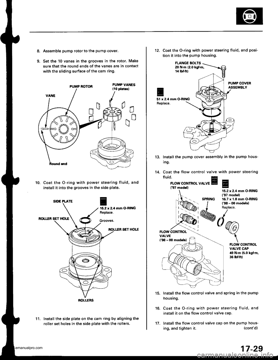
Asssmble pump rotor to the pump cover,
Set the 10 vanes in the grooves in the rotor, Make
sure that the round ends of the vanes are in contact
with the sliding surface of the cam ring.
PUMP ROTOR
Coat the O-ring with power steering fluid, and
install it into the grooves in the side plate.
ftm GRING
ROL1IR SET HOI,E
SET HOTT
Install the side plate on the cam ring by aligning the
roller set holes in the side Dlate with the rollers.
10.
I
15.2 x 2-1Replace.
Gfooves.
SII'E PLATE
BOLI-ERS
11.
17.
ing, and tighten it.
12. Coat the O-ring with power steering fluid,
tion it into the pump housing.
and posi-
FLANGE BOI-TS20 N.m (2.0 kgt m,14 tbf.ft)
51 x 2.4 mm O-RINGReplace.
13.
14.
lnstall the
ing.
Coat the
fluid.
pump cover assembly in the pump hous-
tlow control valve with power steering
FLOW CONTROL VALVE137 modol)
FLOW CONTBOLVALVEl'98 - 0O modeltl
'15.
16.
Install the flow control valve and spring in the pump
housing.
Coat the O-ring with power steering fluid, and
install it on the flow control valve cap.
Install the flow control valve cap on the pump hous-
Eg
SPRING
15.2 x 2.4 mm O.RING('97 modell16.7 x'1.8 mm O-RING
FLOW CONTROLVALVE CAP49 N.m (5.0 kgl.m,36 tbf.ft)
(cont'd)
17-29
www.emanualpro.com
Page 875 of 1395
Power Steering Pump
Reassembly (cont'dl
'18. Coat the O-ring wjth power steering fluid, andinstall it into the grooves in the inlet joint.
FLANGE BOLTS11 N.m 11.1 kgf.m,8 rbf.ft)
'13 x '1.9
Replace.r
E
19.
20.
Install the inlet joint on the pump housing.
Install the pulley as shown below. then loosely
install the pulley nut. Hold the steering pump in avise with soft jaws. Be careful not to damage thepump housing with the jaws of the vise.
17-30
21. Hold the pulley with the speciat toot, and tighten thepulley nut.
Check that the pump turns smoothly by turning thepulley by hand.
www.emanualpro.com
Page 877 of 1395

Power Steering Gearbox
AN'USTABLE HOSE CLAMP
Removal (cont'dl
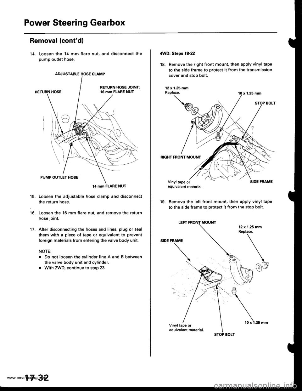
14. Loosen the 14 mm flare
pump outlet hose.
nut, and disconnect the
14 mm FLARE NUT
15. Loosen the adjustable hose clamp and disconnect
the return hose,
16. Loosen the 16 mm flare nut, and remove the return
hose joint.
17. After disconnecting the hoses and lines, plug or seal
them with a piece of tape or equivalent to prevent
foreign maisrials from entering the valve body unit.
NOTE:
. Do not loosen the cylinder line A and B between
the valve body unit and cylinder.
. With 2WD, continue to step 23.
17 -32
STOP BOLT
10 x 1.25 mm
4WD: Stepr 18-22
18. Removethe right tront mount, then apply vinyl tape
to the side frame to protect it from the transmission
cover and stop bolt.
12 x 1.25 fiiAReplace.
RIGHT FRONT MOUNT
x 1,25 mm
SIDE FRAME
'19. Remove the left front mount, then apply vinyl tape
to the side frame to protect it from the stop bolt.
Vinyltape orequivalgnt material.
Vinyltap€ orequival€nt m6terial.
www.emanualpro.com
Page 897 of 1395
Power Steering Gearbox
Installation (cont'd)
8, Install the left front mount. Tighten the mountingbolts in order: A and B.
LEFT FRONT MOUNT
B-12 x 1,25 mm59Nm(6.0 kgtm,,€ lbl.ftlReplaca.
9. Instsll the right front mount, Tighten the mountingbolts in order: A and B.
B-12 x 1.25 mm59 N.m16.0 ks[.m, ,|:| lbf.ftlReplace.
A-10 x 1.25 mm4,1 N.mla.s kgt m, 33 lbf.ft)
A-10 x 1.25 mma,a N.m
10. Remove the vinyl type from the side frame (both
sides).
17-52
11. Installthe return hose joint by tightening the 16 mmflare nut.
AD.'USTAB[T HOSE CLAMP(For installationreter to page 17,23)
RETURN HOSE JOINT:16 mm FLARE NUT28 N.m12.9 kg{.m.21 lbt{t)
14 mm FLARE NUT37 N.m(3.8 ksf.m, 27 lbl'frl
't2.
13.
Connect the return hose securely. and tighten theadjustable hose clamp.
Connect the pump outlet hose, and tighten the l4mm flare nut.
NOTE: Make sure that there is no interferencebetween the fluid lines, the rear beam or any otherparts.
www.emanualpro.com
Page 931 of 1395

Bleeding
CAUNON:
. Do not spill brake tluid on the vehicle. it may damage
the paint; if brake fluid does contaqt th€ paint, wash
it otf immodiately with water.
. Maks sure no dirt oy other forsign matter is allowsd
to contaminate the brake fluid.
NOTE:
. Do not reuse the drained fluid.
. Always use Genuine Honda DOT 3 Brake Fluid. Using
a non-Honda brake fluid can cause corrosion and
decrease the life of the svstem.
. The reservoir on the master cylinder must be at the
MAX (upper) level mark at the start of bleeding pro-
cedure and checked after bleeding each brake caliper
and wheel cylinder. Add fluid as required.
1, Make sure the brake fluid level in the reservoir is at
the MAX (uDDer) level line.
MAX {UPPER) LEVELLINE
RESERVOIR
MASTER CYLINDER
2.
3.
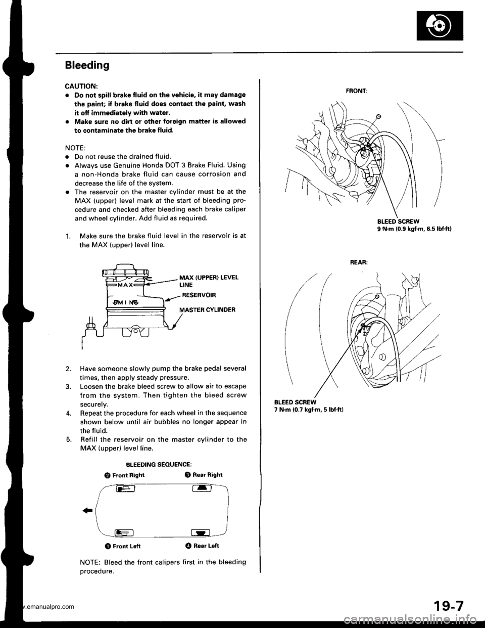
Have someone slowly pump the brake pedal several
times, then apply steady pressu.e.
Loosen the brake bleed screw to allow air to escape
from the system. Then tighten the bleed screw
securely.
Repeat the procedure for each wheel in the sequence
shown below until air bubbles no longer appear in
the tluid.
Refill the reservoir on the master cvlinder to the
MAX (upper) level line.
ALEEDING SEOUENCE:
O Front RightGt Rear Right
O Front LeflO Rear Left
NOTE: Bleed the front calipers first in the bleeding
procedure.
4.
FRONT:
BLEEO SCREW7 N.m (0.? kgf.m, 5 lbf.ftl
19-7
www.emanualpro.com
Page 948 of 1395

Anti-lock Brake System (ABSI,'97 - 00 Models
Special Tools ............. 19-26
Component Locations ......................... 19-27
Anti-lock Brake System (ABS)
Features/Construction ............. ......, 19-2A
Circuit Diagram ......... 19-32
ABS Control Unit Terminal
Arrangement ......... 19-34
Troubleshooting Precautions ............. 19-36
Diagnostic Trouble Gode (DTC)
Diagnostic Trouble Code (DTC)
Indication (SCS Model ................ 19-38
DTG Erasure (MES Mode) ............... 19-39
Troubleshooting lndex .................... 19-40
Troubleshooting
ABS Indicator Light Does Not
Come On ............ 19-41
ABS Indicator Light Does Not
Go Off (No DTC) ........................... 19-43
DTC 1r - 18:
Wheel Sensor .... 19-45
DTC 31 - 38:
Solenoid ............. 19-47
DTC 51 - 53:
ABS Pump Motor ......................... 19-49
DTC 54:
Main Relay ......... 19-52
DTC 61:
lgnition Voltage ........................... 19-54
DTC 81:
Central Processing Unit (CPU) .... 19-55
Modulator Unit
Removal/lnstallation ....................... 19-56
ABS Control Unit
Replacement ..,...... 19-57
Pulsers/Wheel Sensors
Inspection .............. 19-57
Wheel Sensor Replacement ............ 19-58
www.emanualpro.com
Page 950 of 1395
Component Locations
NOTE: The illustrations show the '97 - 98 models. The '99 - 00 models are similar.
ABS CONTROL UNITRIGHT-REAR WHEEL SENSOR
UNDER.HOOD ABSFUSE/RELAY BOX
RIGHT.FRONT WHEELSENSOR CONNECTOR
RIGHT-FRONTWHEEL SENSORRIGHT-REAB WHEELSENSOR CONNECTOR
MODULATOR UNIT
LEFT.FRONT WHEEL SENSOB
UNDER.DASH FUSE,/RELAY 8OX
UNDER.HOOO FUSE/RELAY AOX
IGl I(, AI FUSE
ABS +B 120 Al FUSEPUMP MOTOR ('II AI FUSE
HOBN/STOP I15 AI FUSE
UNDER.HOOD ABS FUSE/RELAY BOX
LEFT.FRONT WHEELSENSOE CONNECTOR
GAUGE ASSEMBLY
ABS INDICATOR
UNDER-DASH FUSE/NELAY BOX
METER {7.5 AI FUSE
MOTOR RELAY
19-27
SERVICE CHECK CONNECTOR {2PI
D!
trtrtr
[r D!
ABS {7.5 AI FUSEMTR CHECK 17.5 AI FUSE
www.emanualpro.com
Page 953 of 1395

Anti-lock Brake System (ABS)
Features/Gonstruction (cont'd)
ABS Modulator
The ABS modulator consists of the inlet solenoid valve, outlet solenoid valve, reservoir, pump, pump motor and thedampjng chamber.
The modulator reduces the caliper fluid pressure directly. lt is a circulating-type modulator because the brake fluid circulatesthrough the caliper, reservoir and the master cylinder.The hydraulic control has three modes: pressure reduction, pressure retaining and pressure intensifying modes.The hydraulic circuit is the independent four channel-type, one channel for each wheel.
SOLENOID VALVE
t-
Pressure intensifying mode: Inlet valve open, outlet valve closed,
Pressure retaining mode:
Pressure reduction mode:
Motor operation mode:
Master cylinder fluid is pumped out to the caliper.Inlet valve closed, outlet valve closed.
Caliper fluid is retained by the inlet valve and outlet valve.Inlet valve closed, outlet valve ooen
Caliper fluid flows through the outlet valve to the reservoir.When starting the pressure reduction mode. the pump motor is ON.When stopping ABS operation, the pump motor is OFF.The reservoir fluid is pumped out by the pump, through the damping chamber, to the mastercylinder.
PUMP MOTOR
19-30
www.emanualpro.com