Page 540 of 1395

Description
Hydraulic Control
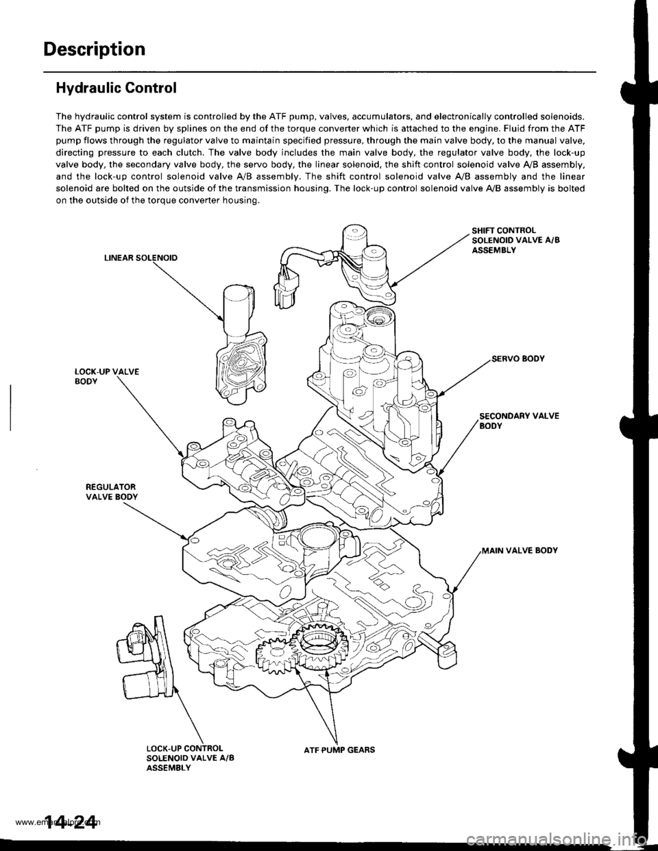
The hydraulic control system is controlled by the ATF pump, valves, accumulators, and electronically controlled solenoids.
The ATF pump is driven by splines on the end of the torque converter which is aftached to the engine. Fluid from the ATF
pump flows through the regulator valve to maintain specified pressure, through the main valve body, to the manual valve,
directing pressure to each clutch. The valve body includes the main valve body, the regulator valve body, the lock-up
valve body, the secondary valve body, the servo body, the linear solenoid, the shift control solenoid valve Ay'B assembly,
and the lock-up control solenoid valve A/B assembly. The shift control solenoid valve A,/B assembly and the linear
solenoid are bolted on the outside of the transmission housing. The lock-up control solenoid valve A,/B assembly is bolted
on the outside of the torque converter housing.
LINEAR
SHIFT CONTROLSOLENOID VALVE A/BASSEMBLY
SECONDARY VALVEBODY
REGULATORVALVE BOOY
VALVE BODY
SOLENOID VALVE A/BASSEMELY
N
ATF PUMP GEARS
14-24
www.emanualpro.com
Page 542 of 1395
Description
Hydraulic Control (cont'd)
Regulator Valve Body
The regulator valve body is located on the main valve body. The regulator valve body consists of the regulator vatve, thetorque converter check valve. the cooler relief valve, and the lock-up control valve.
Lock-up Valve Body
The lock-up valve body, with lock-up shift valve and lock-up timing valve, is located on the regulator valve body.
LOCK.UP SHIFT
NMING VALVE
COOLER RELIEF VALVE
VALVE
14-26
www.emanualpro.com
Page 545 of 1395

Hydraulic Flow
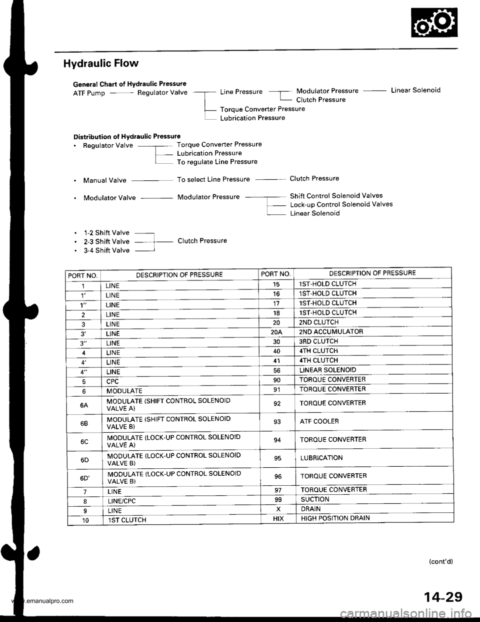
General Chart of Hydraulic Pressure
ATF pump - Regulator Valve -a LinePressure 5 Modulator Pressure - Linear Solenoid
| - Clutch Pressure
L- Toroue Converter Pressure
L LUbrication Pressure
Distribution ol Hydraulic Pressure
. Regulator Valve -"- Torque Converter Pressure
L- Lubrication PressureI To regulate Line Pressure
. Manual Valve To select Line Pressure - Clutch Pressure
. Modulator Valve Modulator Pressure -- ---- Shift Control Solenoid Valves
f- Lock-up Control Solenoid valves
L Linear Solenoid
. 1-2 Shift Valve ---
. 2-3 Shift Valve -- t- Clutch Pressure
. 3-4 Shift Valve I
PORT NO,DESCRIPTION OF PRESSUREPORT NO,DESCRIPTION OF PRESSURE
1LINE15lST-HOLD CLUTCH
LIN E1ST-HOLD CLUTCH
't'LINE171ST-HOLD CLUTCH
2LINE181ST-HOLD CLUTCH
3LINE202ND CLUTCH
3'�LINE20A2ND ACCUMULATOR
3"LINE303RD CLUTCH
LINE404TH CLUTCH
LINE414TH CLUTCH
LINELINEAR SOLENOID
590TOROUE CONVERTER
MODULATE91TOROUE CONVERTER
6AMODULATE (SHIFT CONTROL SOLENOIOVALVE A)92TOROUE CONVERTER
MODULATE (SHIFT CONTROL SOLENOID
VALVE B)93ATF COOLER
IVODULATE (LOCK.UP CONTROL SOLENOID
VALVE A)94TOROUE CONVERTER
MODUTATE (LOCK-UP CONTROL SOLENOID
VALVE B)95LUBRICATION
6D'MODULATE (LOCK-UP CONTROL SOLENOID
VALVE B)TOROUE CONVERTER
7LIN E97TOROUE CONVERTER
8LINE/CPC99SUCTION
ILINExDRAIN
101ST CLUTCHHIXHIGH POSITION DRAIN
{cont'd)
14-29
www.emanualpro.com
Page 546 of 1395
Description
Hydraulic Flow (cont'dl
lll Position
As the engine turns, the ATF pump starts to operate. Automatic transmission fluid (ATF) is drawn from (99) and dis-charged into (1). Then, ATF flowing from the ATF pump becomes line pressure ('l). Line pressure (1) js regulated by theregulator valve. Torque converter inlet pressure {92) enters (94) of the torque conveTter through the lock-up shift valve anddischarges into (90) The torque converter check valve prevents torque converter pressure from rising. Under this condi-tion, hydraulic pressure is not applied to the clutches.
NOTE;
. When used. "|eft" o. "right" indicates direction on the hvdraulic circutt.. The hydraulic circuit shows the '97 - 98 models {7 positions}; the '99 - 00 models (6 positions) is similar.
'lF'.j.l
14-30
www.emanualpro.com
Page 555 of 1395

Lock-up System
TOROUE CONVERTER
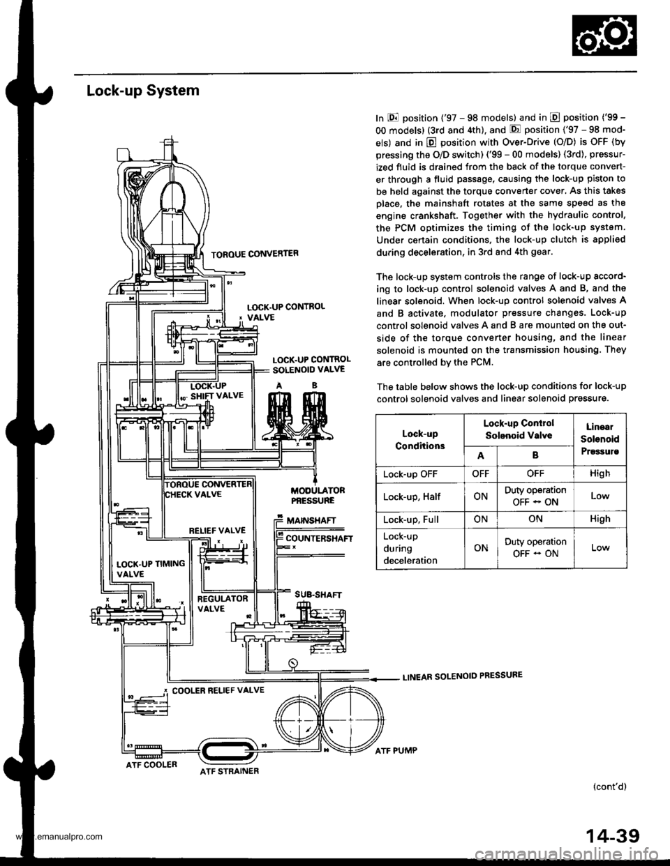
In E position ('97 - 98 models) and in E position ('99 -
OO models) (3rd and 4th), and E position ('97 - 98 mod-
els) and in E position with Over-Drive (O/D) is OFF (by
pressing the O/D switch) ('99 - 00 models) (3rd), pressur-
ized fluid is drained from the back of the torque convert-
er through a fluid passage, causing the lock-up piston to
be held against the torque converter cover, As this takes
Dlace, the mainshaft rotates at the same speed as th8
engine crankshaft. Together with the hydraulic control,
the PCM optimizes the timing of the lock-up system.
Under certain condltions. the lock-up clutch is appli€d
during deceleration, in 3rd and 4th gear.
The lock-up system controls the range of lock-up sccord-
ing to lock-up control solenoid valves A and B, and ths
linear solenoid. When lock-up control solenoid valves A
and B activate. modulator pressure changes. Lock-up
control solenoid valves A and B are mounted on the out-
side of the torque converter housing, and the linear
solenoid is mounted on the transmission housing. They
are controlled bv the PCM.
The table below shows the lock-up conditions for lock-up
control solenoid valves and linear solenoid pressure.
LINEAR SOLENOID PRESSURE
(cont'd)
LOCK.UP CONTROL' VALVE
LOCK.UP CONTROLSOLENOID VALVE
AB
MODULATORPf,ESSURE
MAINSHAFT
COUNTERSHAFT
SUB.SHAFT
Lock-up
Conditions
Lock-up Conirol
Solenoid valveLinaal
Solenoid
PrgssulsAB
Lock-up OFFOFFOFFHigh
Lock-up, HalfONDuty operation
OFF - ONLow
Lock-up, FullONONHigh
Lock-up
during
deceleration
ONDuty operation
OFF - ON
RELIEF VALVE
LOCK'UP TIMINGVALVE
COOLER RELIEF VALVE
ATF COOLERATF STRAINER
ATF PUMP
14-39
www.emanualpro.com
Page 556 of 1395
Description
Lock-up System (cont'dl
Lock-up Clutch
L Ooeration (clutch on)
With the lock-up clutch on, the fluid in the chamber between the torque convener cover and the lock-uD oiston is drainedoff, and the converter fluid exerts pressure through the piston against the torque converter cover, As a result, the conven-er turbine is locked to the converter cover. This bipasses the converter, placing the vehicle in direct drive.
LOCK,UP PISTON
The power flows by way of:
Engine
+
Drive plate
Torque converter cover
I
Lock-up piston
t
Damper spring
{
Turbine
Mainshaft
IOROUECOVER
Operation (clutch off)
With the lock-up clutch off, the fluid flows in the reverse of "clutch on." As a result, the lock-up piston moves away fromthe converter cover, and the torque converter lock-up is released.
Engine
I
Drive plate
{
Torque converter cover
{
Pump
I
Turbine
{
Mainshaft
TOROUECOVER
To ATF cooler{(1\\n1INLET
t
Jtl
ort
MAIf{SHAFT
MAII{SHAFT
14-40
www.emanualpro.com
Page 557 of 1395
TOROUE CONVERTER
No Lock-up
. Lock-up Control Solenoid Valve A: OFF
. Lock-up Control Solenoid Valve B: OFF
. Linear Solenoid Pressure: High
The pressurized fluid regulated by the modulator works
on both ends of the lock-up shift valve. Under this condi-
tion, the pressures working on both ends of the lock-up
shift valve are equal. and the lock-up shift valve is
moved to the right side by the tension of the valve
spring. Fluid trom the ATF pump will flow through the
left side of the lock-up clutch to the torque converter; the
lock-up clutch is OFF.
NOTE: When us€d, "|eft" and "right" indicates direction
on the hydraulic circuit.
+ LINEAR SOLENOID PRESSURE
(cont'd)
LOCK.UP CONTROLSOI-ENOID VALVE
MOOULATORPRESSURE
MAINSHAFT
COUNTERSHAFTRELIEF VALVE
LOCK-UP TIMINGVALVE
i COOLER RELIEF VALVE
ATF STRAINERATF COOLER
ATF PUMP
14-41
www.emanualpro.com
Page 558 of 1395

Description
Lock-up System (cont'dl
a
a
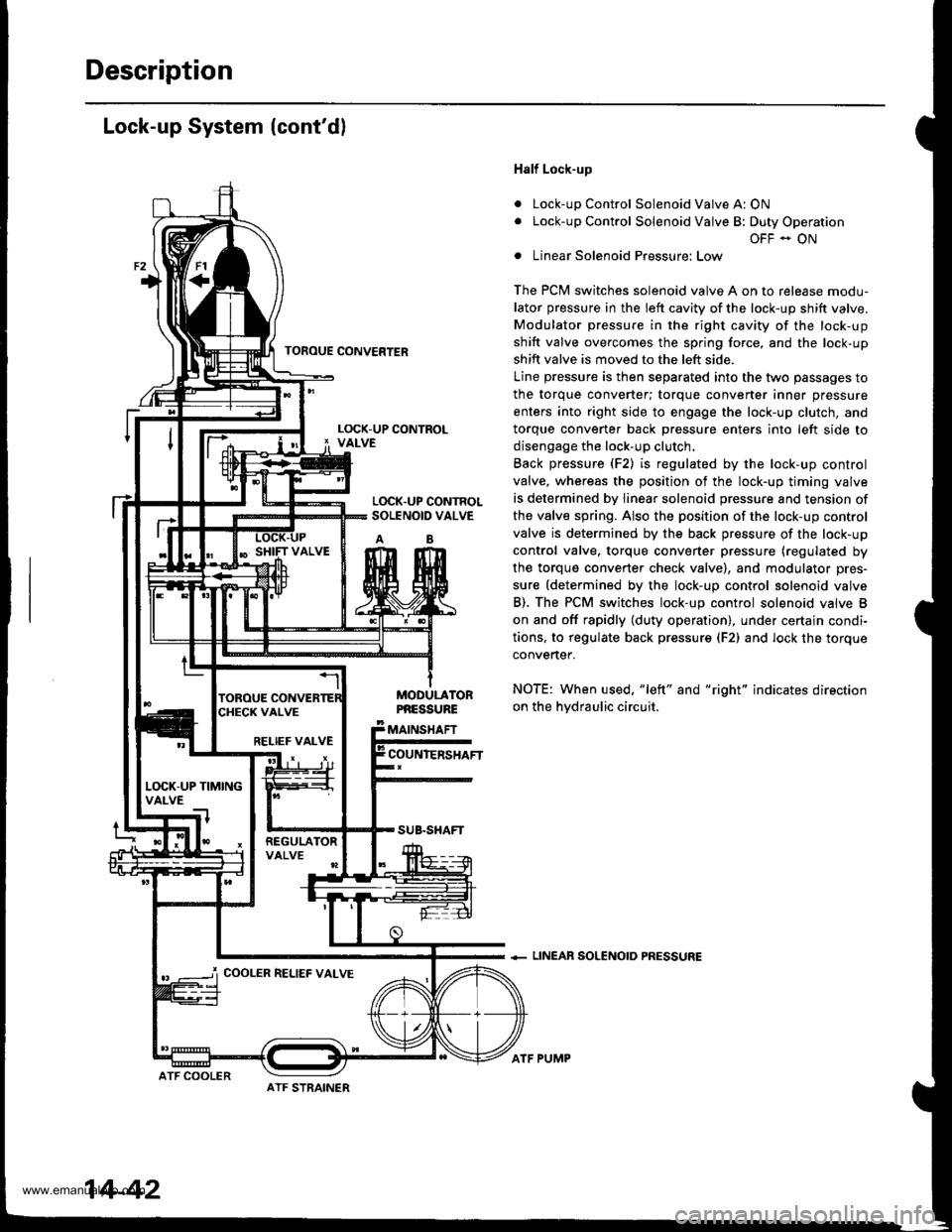
Half Lock-up
Lock-up Control Solenoid Valve A: ON
Lock-up Control Solenoid Valve B: Duty Operation
OFF - ON
Linear Solenoid Pressure: Low
The PCM switches solenoid valve A on to release modu-
lator pressure in the left cavity of the lock-up shift valve.
Modulator pressure in the right cavity of the lock-up
shift valve overcomes the spring force, and the lock-up
shift valve is moved to the left side.
Line pressure is then separated into the two passages to
the torque converter; torque converter inner pressure
enters into right side to engage the lock-up clutch, and
torque convener back Dressure enters into left side to
disengage the lock-up clutch.
Back pressure (F2) is regulated by the lock-up control
valve, whereas the position of the lock-up timing valve
is determined by linear solenoid pressure and tension of
the valve spring. Also the position of the lock-up control
valve is determined by the back pressure of the lock-up
control valve. torque converter pressure (regulated by
the torque converter check valve), and modulator pres-
sure (determined by the lock-up control solenoid valve
B). The PCM switches lock-up control solenoid valve B
on and off rapidly (duty operation), under certajn condi-
tions, to regulate back pressur€ (F2) and lock the torque
convertef.
NOTE: When used, "left" and "right" indicates direction
on the hvdraulic circuit.
+ LINEAR SOLENOID PRESSURE
TOFOUE CONVERTER
L(rcK.UP CONTROLSOLENOID VALVE
AB
MODULATORPNESSURE
MAINSHAFT
COUNIERSHAFTRELIEF VALVE
L(rcK-UP TIMINGVALVE
COOLER RELIEF VALVE
ATF STRAINER
14-42
ATF COOLER
ATF PUMP
www.emanualpro.com