Page 957 of 1395

ABS Control Unit Terminal Arrangement
ABS CONTROL UNIT 26P CONNECTOR
Wire side of female terminals
TeiminalnumbelWiiecolorTerminal3ignTeiminalnamglDescription
Voltrge
tdminalsCondhions(lgnition Switch ON llll)Output voltago
1GRNn/VHTPCOM(Primary
common)
Power source for the solenoidvalve and pump motor.1-GNDON6
ONOV
OFFAC:3-6V
2BLI(WHTSCOM(Secondary
common)
Power source for the solenoid2-GNDOFF
lConnect the SCS seNice] connector IApprox.3 V
BLVBLU(lgnition 2)Detects ignition switch 2signal. (System activate signal)3-GNDBattery Voltage
4BLUA/ELRRO(Rear-right 0)Detocts right-rear wheelsensor srgnat.When the wheel isturned at 1 turn/second.
53 mV or above ondigitaltester (ACrange) {Beference)150 mvtrp or aboveon oscilloscope
GRYRLO(Rear-left 0)Detects left-rear wheel sensorsrgnat.6-19
8GRNFRO(Fronr-right 0)Detects right-front wheelsensor signal.8-21StopsApprox.2.5 VSTOP
{Stop)Detects bfake switch signal.(Prevents unnecessary ABS operation)9-GNDBrake pedal pressed.Battery Voltage
Brake Dedal released.OV
10BRN^/VHTFLO(Front-left 0)
Detects left-front wheel sensorsrgnal.
10-23
When the wheel isturned at 1 turn/second.
53 mV or above ondigitaltester lACrange) (Reference)
150 mvpp or aboveon oscilloscope
StopsADprox. 2.5 V
YELRL-oUT(Rearleft outlet)
Drives left-rear outlet solenoid12.GNDONONOV
OFFAC:3-6V
13RED^/vHTRR.IN(Rear-right
inlet)
Drives right-rear inlet solenoid13.GNDOFF
lConnect the SCS service\ connector IApprox. 3 V
14WHT/GRNB1(Baftery 1)Power source for the solenoidvalve and pump motor.14.GND
Every timeBattery Voltage82(Battery 2)Power source for the solenoidvalve and pump motor.15-GND
16BLKGND2(Ground 2)Ground for the ABS controlunit.16-GNDBelow 0.3 V
't7GRN/YELRR1(Rear-right 1)Detects right-rear wheelsensor signal.'t7 -4
When the wheel is turnedat l turn/second,
53 mV or aboveon digitaltester(AC range)(Reference) 150mVp-p or aboveon oscilloscope
19LT BLURL1(Rearieft 1)Detects left-rear wheel sensorsignal.19-6
GRN/BLKFR1(Front-right 1)Detects right-front wheelsensor srgnat.21-8
23GBN/ORNFL1{Front-left 1}Detects left-front wheel sensorsagnal.23-10StopsApprox. 2.5 V
REDRLI N(Rear-left inlet)
Drives left-rear inlet solenoid
25,GND
ON
=
-9ONOV
AC:3-6V
OFF
/Connect the SCS service] conneclor IApprox. 3 V
26BLKGND3(Gtound 3)Ground tor the ABS controluntI.26-GNDBelow 0.3 V
19-34
www.emanualpro.com
Page 958 of 1395

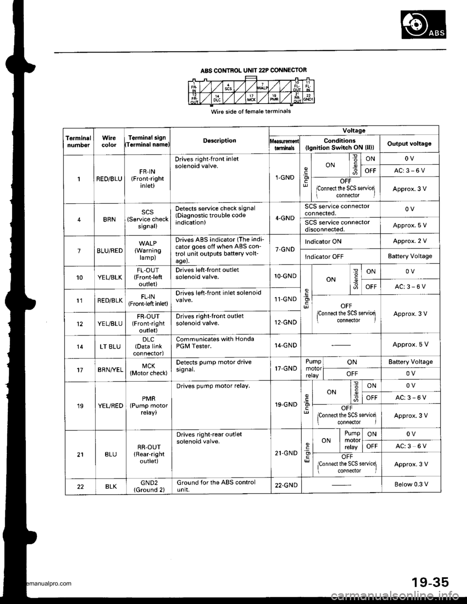
ABS CONTROL UNIT 22P CONNECIOR
Wire side ol lemale terminals
TerminalnumDerWirecolorTerminal 3i9nTerminal nameDescription
Voltage
Conditions(lgnition Switch ON (ll)lOutput voltagetominals
1RED/BLUFR-IN(Front-right
inlet)
Drives right-front inletsolenoid valve.
1-GND.9otur
ONIONOV
OFFAC:3-6V
OFF
lconnect the SCS servicel
connedor lApprox.3 V
BRN(Service checksignal)
Detects service check signal(Diagnostic trouble codeindication)4.GND
SCS service connectorconnected.OV
SCS service connectordisconnected.Approx. S V
7BLU/RED(Warning
ramp)
Drives ABS indicator {The indi-
cator goes off when ABS con-
trol unit outputs battery volt-age).
7.GND
lndicator ONApprox. 2 V
lndicator OFFBattery Voltage
10YEUBLKFL-OUT(Frontieft
outlet)
Drives left-front outletsolenoid valve.1O-GNDON
=
I
ONOV
OFFAC:3-6V
l'lRED/BLKFL-IN(Front-left inlet)
Drives left-front inlet solenoid11-GNDOFF
lconnect the SCS servicq connector lApprox.3 V
YEUBLUFR-OUT(Front-right
outlet)
Drives right-front outletsolenoid valve.12-GND
14LT BLU(Data linkconnectod
Communicates with HondaPGM Tester.14-GNDApprox. 5 V
17BRN/YELMCK(Motor check)
Detects PumP motor drivesignal.17-GNDPumpmotorrelay
ONBattery Vollage
OFFOV
19YEUREDPMR(Pump motorreray,
Drives pump motor relay.
19.GNDcl)
ON6IONOV
OFFAC:3-6V
OFFponnecl the SCS service]
connector IApprox.3 V
BLURR-OUT(Rear-right
outlet)
Drives right-rear outletsolenoid valve.
21.GND'a)
ONPumpmororrcray
ONOV
OFFAC:3 6V
OFF
lconnect the SCS service] connector lApprox.3 V
BLKGND2(Ground 2)Ground for the ABS controlunit.22.GNDBelow 0.3 V
19-35
www.emanualpro.com
Page 968 of 1395

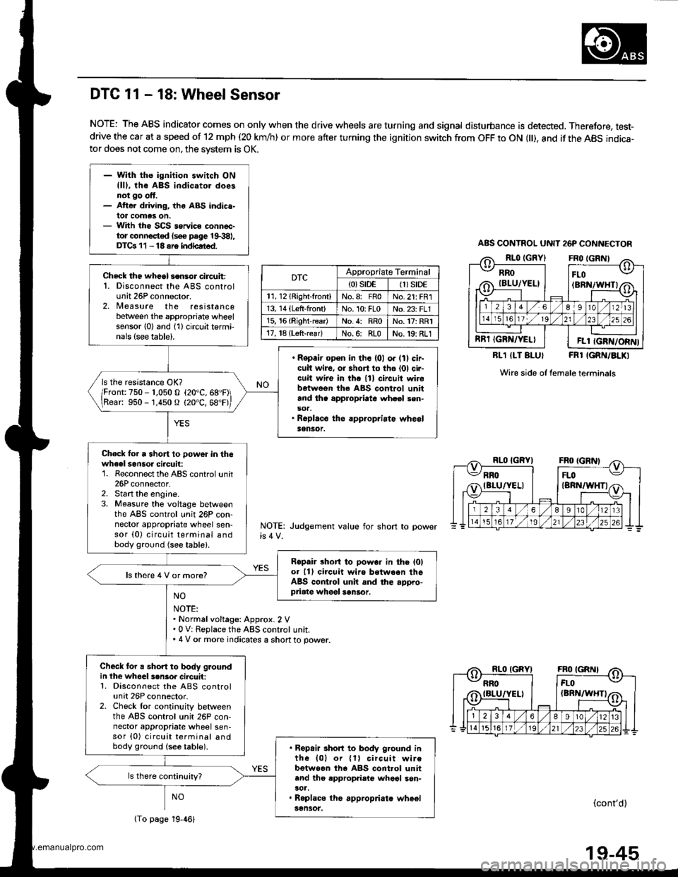
- With ths ignition switch ONllll, the ABS indicatol doesnot go ott.- Atte. driving, the ABS indica-lot comas on.- With the SCS service connec-tor connocted (s€€ page 19.381,DTGr 11 - 18 sre indbated.
Check the whcol sensor circuit:1. Disconnect the ABS controlunit 26P connector.2, Nleasure the resistancebetween the appropriate wheelsensor l0) and 1'l) circuit termi-nals {see table).
. Ropair op€n in th. {01 o. lll cir-cuit wire, oa short to the (01 cir-cuit wire in the lll circuit wirobetweon the ABS control unitand th. appropriate whasl sen-sot.. Roplace the rpp.opriatc whe6lSensor.
ls the resistance OK?
/Fronr:750 - r,050 o (20"C,68"F\
\Rear: 950 -'1,450 O (20"C, 68'F,
Chock lor a short 10 power in thewheel sensoa ciacuil:1. Reconnect the ABS control unit26P connector.2. Start the engine.3. Measure the voltage betlveenthe ABS control unit 26P con-nector appropriate wheel sen-sor (0) circuit terminal andbody ground (see table).
Ropair lhort to pow.r in the l0lot 11) circuit wiro between theABS control unit and the appro-priate whool sen6or.
ls there 4 V or more?
Check for a short to body groundin the whoal s.n3or cilcuit:1. Disconnect the ABS controlunit 26P connector.2. Check lor cont;nuity betweenthe ABS control unit 26P con-nector appropriate wheel sen-sor {0) circuit terminal andbody ground {se6 table).. Ropair short to body g.ound inth6 {01 or {1} circuit wirebotweon th6 ABS cont.ol unitand tho appropriato wheol son-aot.. Roplace tho appropriate wheelsensot.
DTC 11 - 18: Wheel Sensor
NOTE: The ABS indicator comes on only when the drive wheels are turning and signal disturbance is detected, Therefore, test-drive the car at a speed of 12 mph (20 km/h) or more after turning the ignition switch from OFF to ON l), and if the ABS indica-tor does not come on, the svstem is OK.
RLl (LT BLUI FRl IGRN/BLKI
Wire side of female terminals
NOTE: Judgement value for short
NO
NOTE:. Normalvoltage: Approx. 2 V.0 V: Replace the ABS control unit.. 4 V or more indicates a shon to power.
NO(cont'dl
ABS CONTNOL UNIT 26P CONNECTOR
RROIBLU/YEL}
RRT IGRN/YELI
FLO(BRN/WHTI
FLl IGFN/ORN}
DTCAppropriate Terminal
{0}srDE(1)S|DE
11, l2lRight-front)No.8: FnoNo.21: FR1
13, 14 (Left-front)No. 10rFLoNo. 23: FLl
15, 16 (RightreadNo.4: RRoNo.17: RR1
17, l8 (Lsft-rear)No.6: RLoNo.19: RL1
(To page 19-46)
19-45
www.emanualpro.com
Page 980 of 1395
ABS Control Unit
Pulsers/Wheel
Sensors
Replacement
Remove the passenger's side kick panel.
Disconnect the ABS control unit connectors.
Remove the ABS control unit.
Install the ABS control unit in the reverse order ofremovat.
ABS CONTROL UNIT
CONNECTORS
L
Inspection
1.Check the front and rear pulser for chipped or dam-
aged teeth.
Measure the air gap between the wheel sensor andpulser all the way around while rotating the pulser.
lf the gap exceeds 1.0 mm (0.04 in), check for a bentsusDension arm.
Standard: o.il - 1.0 mm 10.02 - 0.04 inl
Front/Rear
Remove the rear brake drum to insDect the rear wheolsensor air gap,
0.4 - 1.0 mm(0.02 - 0.04 inl
19-57
www.emanualpro.com
Page 982 of 1395

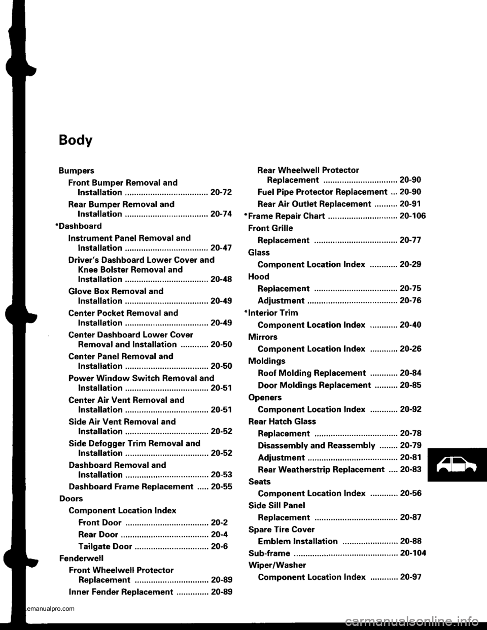
Body
Bumpers
Front Bumper Removal and
fnstaflation .........20-72
Rear Bumper Removal and
fnstaflation .........20-74
'Dashboard
lnstrument Panel Removal and
lnstallation .........20-47
Driver's Dashboard Lower Cover and
Knee Bolster Removal and
Installation .........20-48
Glove Box Removal and
lnstallation .........20-49
Center Pocket Removal and
lnstallation .........20-49
Center Dashboard Lower Cover
Removal and lnstallation ............ 20-50
Center Panel Removal and
lnstallation .........20-50
Power Window Switch Removal and
lnstallation .........20-51
Center Air Vent Removal and
lnstallation .........20-51
Side Air Vent Removal and
fnstallation .........20-52
Side Defogger Trim Removal and
fnstallation .........20-52
Dashboard Removal and
lnstallation .........20-53
Dashboard Frame Replacement ..... 20-55
Doors
Component Location Index
Front Door ,,...,,,,20-2
Rear Door ...........20-4
Tailgate Door ................................ 20-6
Fenderwell
Front Wheelwell Protector
Replacement .....20-89
Inner Fender Replacement .,.....,.,.... 20-89
Rear Wheelwell Protectol
Replacement .....20-90
Fuel Pipe Protector Replacement ... 20-90
Rear Air Outlet Replacement .......... 20-91
*Frame Repair Chart .............................. 20-106
Front Grille
Repf acement .........20-77
Glass
Component Location Index ............ 20-29
Hood
Replacement ......,,,20-75
Adjustment ............20-76
*lnterior Trim
Component Location Index ............ 20-40
Mirrors
Component Location Index .........,,, 20-26
Moldings
Roof Molding Replacement ............ 20-84
Door Moldings Replacement .......... 20-85
Openers
Component Location Index ............ 20-92
Rear Hatch Glass
Replacement .........20-74
Disassembly and Reassembly ........ 20-79
Adiustment ............20-81
Rear Weatherstrip Replacement .... 20-83
Seats
Component Location Index ............ 20-56
Side Sill Panel
Repfacement .........20-87
Spare Tire Cover
Emblem Installation ........................ 20-88
Sub-frame ..................20-104
Wiper/Washer
Component Location lndex ,,,,,....... 20-97
www.emanualpro.com
Page 984 of 1395
GLASS RUNCHANNEL
REAR LOWERCHANNEL
\fi\ \\
t\\\\ IIza\\l@'-ua$
REGULATORReplacement, page 20-10
POWER WINDOWMOTOR
k'"""'*^."
OUTER HANOLEReplacement, page 20-8
INNER HANOLE
CYLINDEBPROTECTOR
LATCHPROTECTOR
POWEF
(cont'd)
20-3
@,
,;@
I
POWENwtNDowswtTcH
ACTUATOB
www.emanualpro.com
Page 985 of 1395
Doors
Gomponent Location Index (cont'dl
Rear Door:
NOTE: Refertothe 1997 Series Honda CR-V Bodv RepairManual (P/N 6151030) for rear door removal.
INNER WEATHERSTRIPOUTER MOLOING
DOOR PROTECTION
ARMREST
REAR DOOR('97 -98 models)
HINGE
REAR DOOR PANEL1'99 - 00 models)Removal and Installation,page 20 '11
@
ARMRESTBRACKET
Position Adiustment,page 20-22
tu4
dP
@
o
@
Bemoval and Installation,page 20-11
(Left side only,'97 - 98 models)
\
DOOR CHANNEL TAPE
FR,
)Ei
D\
\a
20-4
('99 - 00 models)
www.emanualpro.com
Page 986 of 1395
OUARTERSEAL
OUARTERGLASSReplacement,page 20-13
-flHiili^'i--_Fffi
POWER WINDOWMOTOR
REAR CHANNEL-\UPPERCOLLAR -.-----_----_-""
trw
page 20 2L
LATCHReplacement,page 20'13
POWEB DOORLOCK ACTUATOB
,6S
REGULATORReplacement, page 20'13
GLASS RUNCHANNEL
FRONT LOWERCHANNEL
STRIKERAdjustment,
l
I
W*
INN€R HANDLE
/ eowea wrruoow
I sYtfcH
s /* /
M-q/-\
flsg
LOCK RODPROTECTORCItr'6,1-
iI
\LOCKCRANK
LATCHPROTECTOB
(cont'd)
20-5
www.emanualpro.com