1998 HONDA CR-V dtc
[x] Cancel search: dtcPage 598 of 1395

Electrical Troubleshooting ('97 Model)
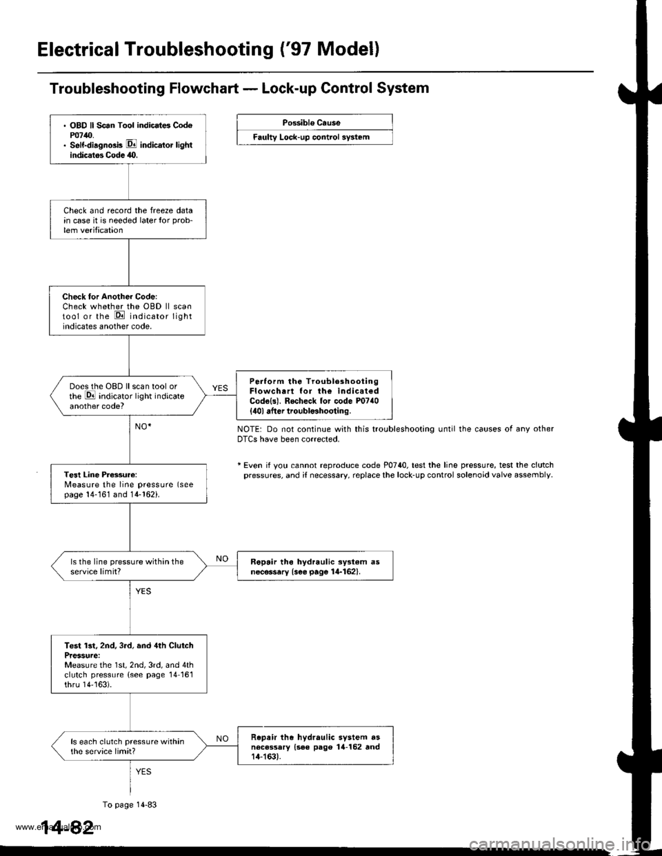
. OBD ll Scan Tool indicrt6 Cod6P0740.. Self-diagno3b E indicator lightindicatos Codc 40.
Check and record the freeze datain case it is needed laterlor prob-
lem verification
Check tor Another Code:Check whether the OBD ll scantool or the E indicator lightindicates another code.
Perlorm the TroubleshootingFlowchart lor th€ indicat€dCodo{s). Rocheck tor code P0740
{ilol after troubl$hooting.
Does the OBD ll scan tool orthe E indicator light indicateanother code?
Tesl Line Pressure:Measure the line pressure (seepage 14-161 and 14-162).
ls the line pressure within theservice limit?R6pair tho hydraulic ayst€m asnecessary {see page 14-162}.
Test lst, 2nd, 3rd, and 4th ClutchPressure:Measure the 1st, 2nd, 3rd, and 4thclutch pressure (see page 14161thru 14''163).
Repair the hydraulic system dsnecessary {see pago 14-152 rnd14-163).
ls each clutch pressure withinthe service limit?
Troubleshooting Flowchart - Lock-up Control System
Possiblo Cause
Faulty Lock-up control sy3t6m
NOTE: Do not continue with this troubleshooting until the causes of any otherDTCS have been corrected.
* Even if yotl cannot reproduce code P0740. test the line pressure, test the clutchpressures, and i{ necessary, replace the lock-up control solenoid valve assembly
1
To page 14-83
4-82
www.emanualpro.com
Page 600 of 1395

Electrical Troubleshooting ('97 Model)
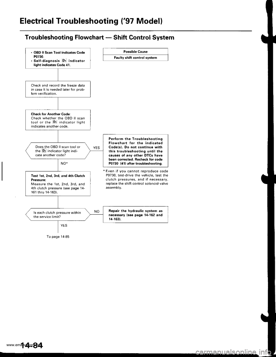
Troubleshooting Flowchart - Shift Control System
Possible Cause
F""lty "t lft ".tttr"l "y"t..
+ Even it you cannot reproduce codeP0730, test drive the vehicle, test theclutch pressures, and if necessary,replace the shift control solenoid valve
. OBD ll Scan Tool indicates CodeP0730.. Selt-diagnosis E,l indicatorlight indicates Code 41.
Check and record the freeze datain case it is needed later for prob-lem verification.
Check tor Another Code:Check whether the OBD ll scantool or the Pll indicator lightindicates another code,
Pertorm the TroubleshootingFlowchart for the indicatedCodels). Do not conlinu€ withthis troubleshooting until thecauses of anv other DTCS havebeen corrected. Recheck for codeP0730 {41) after troubloshooting.
Does the OBD ll scan tool orthe E indicator light indi-cate another code?
Test lst. 2nd, 3rd. and 4th ClutchPressure:Measure the 1st, 2nd, 3rd, and4th clutch pressure (see page 14-161 thru 14-163).
Repair the hydraulic svstem asnecessary lsee page 1,1-162 andr4-1631.
ls each clutch pressure withinthe service limit?
To page 14-85
www.emanualpro.com
Page 635 of 1395

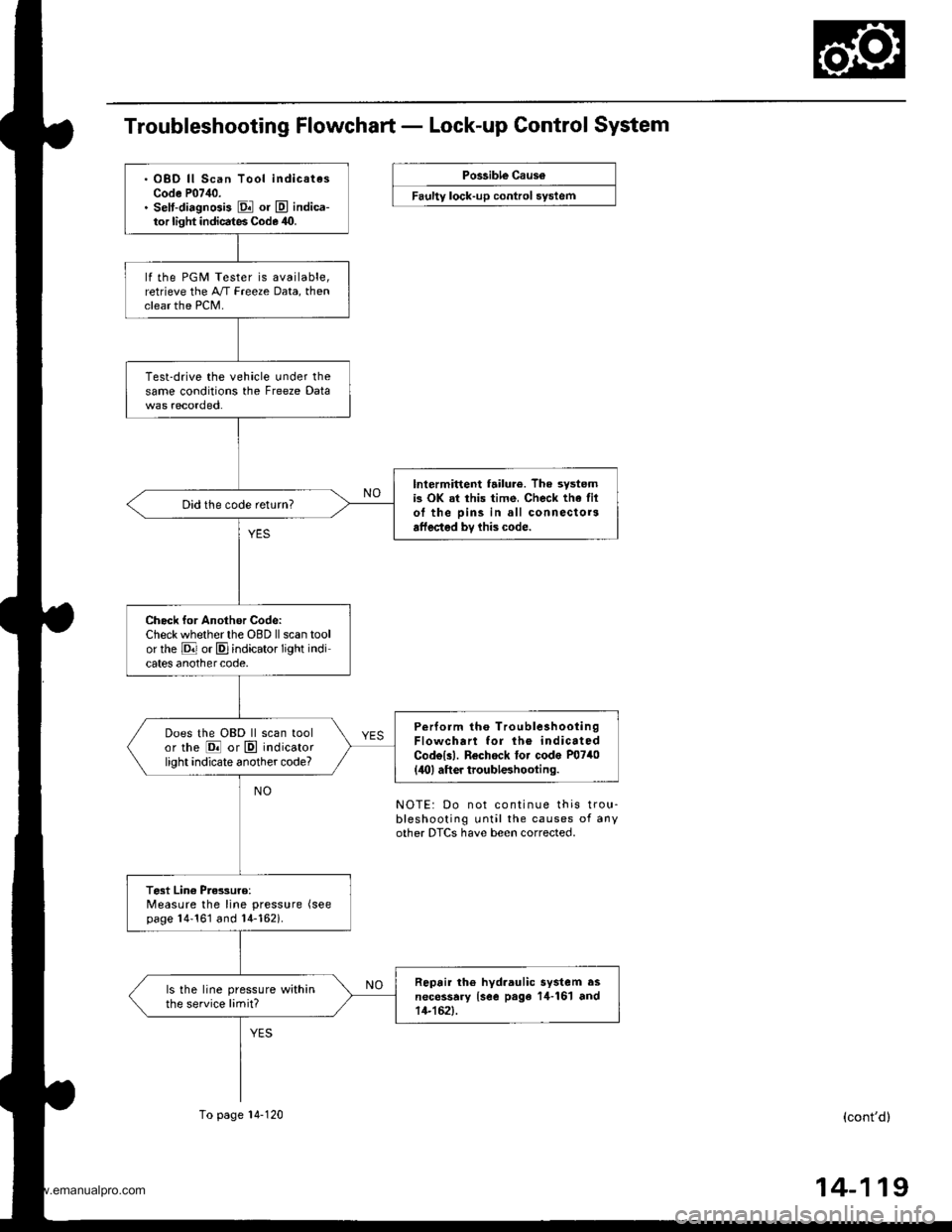
Troubleshooting Flowchart - Lock-up Control System
Possible Caus6
Faulty lock-up control system
. OBD ll Scan Tool indicatesCode P07,10.. selt-diagnGis El or E indica-tor light indicates Code 40.
lf the PGM Tester is available,retrieve the A/T Freeze Data, thenclear the PCM.
Test-drive the vehicle under thesame conditions the Freeze Data
lntermittent failur6. The systemis OK at this time, Check the filol the pins in all connectorsaffected bv lhis code.
Did the code return?
Check for Another Codc:Check whether the OBD ll scan toolor rhe E or E]indicator light indicates anothercode,
Perform tho TroubleshootingFlowchart for lh6 indicatedCodolll. Rechock tor code P0740(,lO) aft er troubleshooting.
Does the OBD ll scan toolor the @ or E indicatorlight indicate another code?
Test Lin€ Pres3uro:Measure the line pressure (see
page 14'161 and 14-162i.
Repair th6 hyd.aulic system asnecessary {see page 14-161 and14-152).
ls the line pressure withinthe service limit?
To page 14-120
NOTE: Do not continue this trou-bleshooting until the causes of anyother DTCS have been corrected.
(cont'd)
14-119
www.emanualpro.com
Page 637 of 1395

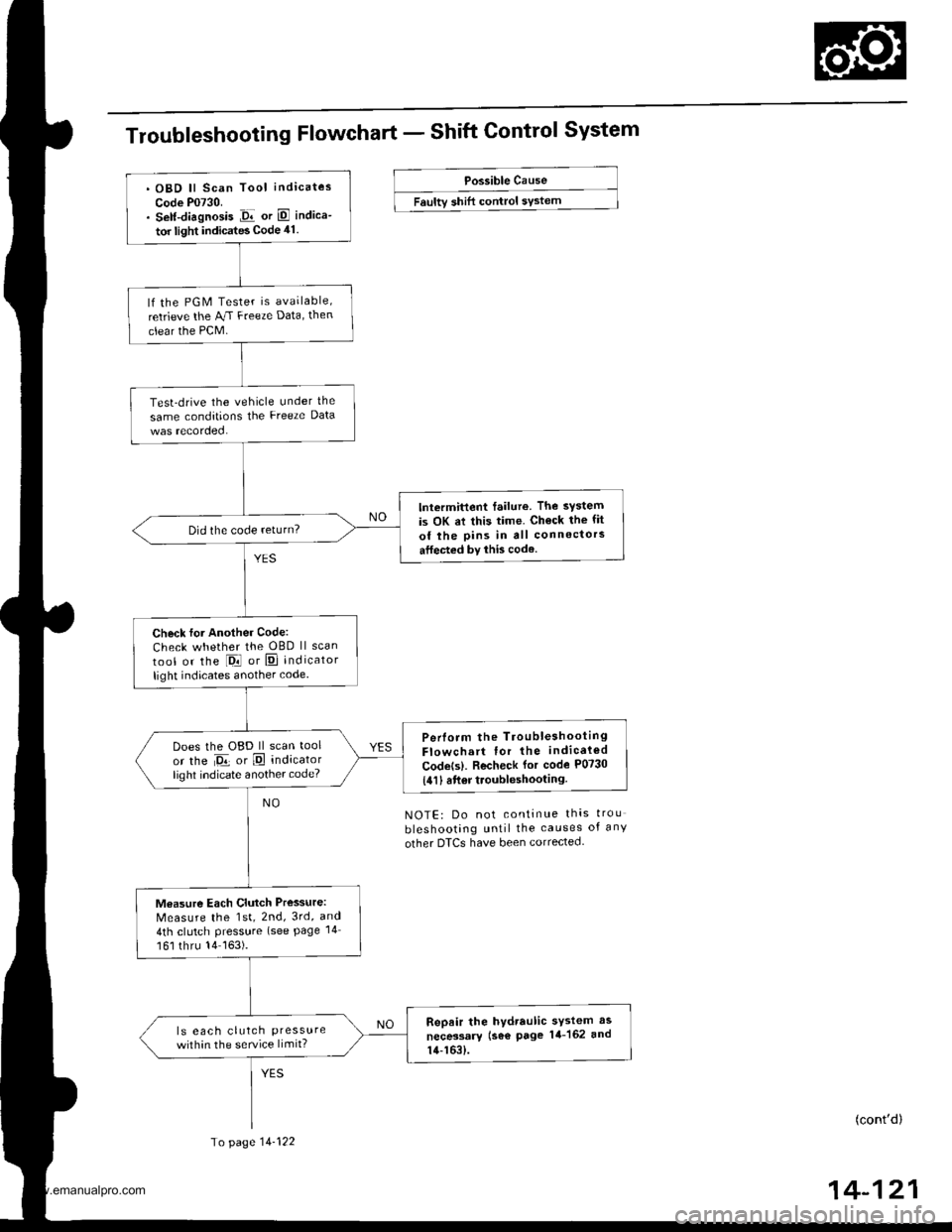
Troubleshooting Flowchart - Shift Control System
Possible Cause
Faultv shift control sYstem
NOTE: Do not continue thas trou
bleshooting until the causes of any
other DTCS have been corrected.
(cont'd)
14-121
. OBD ll Scan Tool indicates
Code P0730.. Self-diagnosis Jir or E indica-
tor light indicates Code 41.
lf the PGM Tester is available,
retrieve the AJ.I Freeze Data, then
clear the PCM.
Test-drive the vehicle under the
same conditions the Freeze Data
lntermittent failure. The system
is OK at this time. Ch€ck the fit
of the pins in all connectors
atfected by this code.
Did the code return?
Check for Another Code:
Check whether the OBD ll scan
tool or the l-Drl or E] indicator
light indicates another code.
Perlorm the TroubleshootingFlowchart for the indicaled
Codets). Recheck for code P0730
{411 6ft6r troubleshooting.
Does the OBD ll scan tool
or the Da or E indicatorlighl indicate another code?
Measure Each Clutch Pressure:
Measure the 1st, 2nd, 3rd, and
4th clutch Pressure (see Page 14
161 thru 14163).
Repair the hydraulic sYstem as
necessary (se€ page 14-162 and
14-163).
ls eac h clutch Pressurewithin the service limit?
To page 14-122
www.emanualpro.com
Page 948 of 1395

Anti-lock Brake System (ABSI,'97 - 00 Models
Special Tools ............. 19-26
Component Locations ......................... 19-27
Anti-lock Brake System (ABS)
Features/Construction ............. ......, 19-2A
Circuit Diagram ......... 19-32
ABS Control Unit Terminal
Arrangement ......... 19-34
Troubleshooting Precautions ............. 19-36
Diagnostic Trouble Gode (DTC)
Diagnostic Trouble Code (DTC)
Indication (SCS Model ................ 19-38
DTG Erasure (MES Mode) ............... 19-39
Troubleshooting lndex .................... 19-40
Troubleshooting
ABS Indicator Light Does Not
Come On ............ 19-41
ABS Indicator Light Does Not
Go Off (No DTC) ........................... 19-43
DTC 1r - 18:
Wheel Sensor .... 19-45
DTC 31 - 38:
Solenoid ............. 19-47
DTC 51 - 53:
ABS Pump Motor ......................... 19-49
DTC 54:
Main Relay ......... 19-52
DTC 61:
lgnition Voltage ........................... 19-54
DTC 81:
Central Processing Unit (CPU) .... 19-55
Modulator Unit
Removal/lnstallation ....................... 19-56
ABS Control Unit
Replacement ..,...... 19-57
Pulsers/Wheel Sensors
Inspection .............. 19-57
Wheel Sensor Replacement ............ 19-58
www.emanualpro.com
Page 952 of 1395

ABS Control
The ABS control unit detects the wheel speed based on the wheel sensor signal it received, then it calculates the vehicle
speed based on the detected wheel speed. The control unit detects the vehicle speed during deceleration based on the
rate of deceleration.
The ABS control unit calculates the slip rate of each wheel, and it transmits the control signal to the modulator unit
solenoid valve when the slip rate is high
The pressure reduction control has three modes: pressure reducing, pressure retaining, and pressure intensi{ying modes.
Self-diagnosis Function
The ABS control unit is equipped with a main cPU and a sub cPU, that check each other for problems.
The CPUs check the circuit of the system.
When the CPUS detect failure, they shift to the "system down mode" or the "control inhibition mode".
The self-diagnosis can be classitied into these four categories:
O: Initial diagnosis
O: Except ABS control
O; During ABS control
@: During warning
On-board Diagnosis Function
The ABS system can be diagnosed with the Honda PGM Tester.
The ALB Checker cannot be used with this system. For air bleeding. and checking wheel sensor signals, use the Honda
PGIM Tester. See the Honda PGM Tester user's manuals for specific operating instructions.
(cont'd)
19-29
ABS CONTROL I-INIT
MODEABSINDICATOR LIGHTMAIN
RE LAY
SOLENOID
VALVERestan conditionDTC
SYSTEM
DOWNONNo
operatron
Drive
inhibitionOperation*rlgnition
switchOFF - oN (ll)Memory
CONTROL
INHIBITIONONNo
operaton
Drive
inhibitionOperationAutomaticlVemory
*1: Except CPU failure
www.emanualpro.com
Page 959 of 1395

Troubleshooting Precautions
ABS lndicalor
1 lf the system is oK, the ABS indicator goes off two seconds after turning the ignition switch oN 1l) wathout staningthe engine, and then comes on again and goes off after two seconds. This occurs because the ABS control unit isturned on by the lG2 power source.2. The ABS indicator comes on when the ABS control unit detects a problem in the system. However, even thouoh thesystem is operating properly, the ABs indicator will come on too, under the following conditions:. Signal disturbance
. Wheel spin
. Only drive wheels rotate. Battery voltage fluctuates
To determine the actual cause of the problem, question the customer about the problem, taking these conditions intoconsideration:
3 When a problem is detected and the ABS indicator comes on, the indicator can stay on until the ignition switch isturned OFF, or it can automatically go off, depending on the mode.. Indicator stays on untilthe ignition switch is turned off: When the system is in the system down mode.. Indicator automatically goes off: When the system is in the control inhibition mode.4 The ABS indicator stays on when the system is reactivated without erasing the DTC, but it goes off after starting thevehicle.
When the wheel sensor system is faulty and the ABS indicator comes on. the algorithm of the system automatically turnsoff the ABS indicator after the wheel speed signal returns to the normal speed. Also, when the DTc is erased, the cpu isreset and the ABS indicator goes off when the system checked out normal by the initial diagnosis.Therefore, test-drive the vehicle after servicing the wheel sensor system. and be sure that the ABS indicator does notcome on.
5 When the ABS control unit outputs battery voltage to the gauge assembly, the ABS indicator ooes off.
Diagnostic Trouble Code (DTCI
1. The diagnostic trouble code (DTc) is memorized when a problem is detected and the ABS indicator does not go off,or when the ABS indicator comes on.The DTc is not memorized when the ABS indicator comes on unress the cpu is activated,2 The memory can hold any number of DTCs. However, when the same DTc is detected twice or more, the tater one iswritten over the old one.
Therefore, when the same problem is detected repeatedly, it is recorded as one DTC.3. The DTCs are indicated in the order of ascending number, not in the order they occur.4. The DTCS are memorized in the EEPROM (non-volatile memorv).Therefore, the memorized DTcs cannot be canceled by disconnecting the battery. perform the specified procedures toerase the DTCS.
Self-diagnosis
1. Self-diagnosis can be classified into these four categories:' Initial diagnosis: Performed right after the eng ine starts and untir theABS indicator goes off.. Except ABS control: Performed when the ABS is not functioning.. During ABS control: Performed when the ABS is functioning.. During warning: Performed when the ABS indicator is ON.2. The system performs the fo|owing contrors when a probrem is detected by the serf-diagnosis:. ABS indicator ON. Memorv of DTC. Mode changetothe "system down mode,, or the ,,control inhibition mode,,.
MODEABS INDICATORMAIN
RELAY
SOLENOID
VALVECPURestart conditionDTC
SYSTEM
DOWNONNo
operation
Drive
inhibitionOperation*rlgnition
switchoFF - ON l)Memory
CONTROL
INHIBITIONONNo
operal|on
Drive
inhibitionOperationAutomaticlMemory
*1: Except CPU failure
19-36
www.emanualpro.com
Page 960 of 1395

Kickback'1. The motor operates when the ABS is functioning. and the fluid in the reservoir is forced out to the master cylinder,
causing kickback at the brake pedal.
2. The ABS control unit operates the solenoid valve when the brake pedal is released after the initial diagnosis You may
hear the solenoid valve operate at this time, but it is normal
Pumo Motol
1. The pump motor operates when the ABS is functioning
2. The ABS control unit checks the pump motor operation during acceleration. You may hear the motor operate at this
time, but it is normal.
Brake Fluid Replacement/Ail Bleeding
L Brake fluid replacement and air bleeding procedures are the same as for vehicles without ABS To ease bleeding, start
with the front wheels.
Troubleshooting
1. The troubleshooting flowchart procedures assume that the cause of the problem is still present and the ABS indicator
is still on. Following the flowchart when the ABS indicator does not come on can result in incorrect diagnosis.
2. Ouestion the customer about the conditions when the problem occurred, and try to reproduce the same conditions
for troubleshooting.
Self-diagnosis is made at various times such as the initial diagnosis, except ABS control, during ABS control, during
acceleration, during the specified vehicle speed, etc. Therefore, the symptom canngt be checked unless the check
conditions match with the problem conditjons
3. When the ABS jndicator does not come on during the test-drive. but troubleshooting is performed based on the DTC,
check lor loose connectors, poor contact of the terminals, etc., before you start troubleshooting.
4. After troubleshooting, erase the DTC and test-drive the vehicle. Be sure the ABS indicator does not come on.
5. The connector illustratjons show the female terminals with a single outline and the male terminals with a double out-
l ne.
ABS Function Test
To simulate ABS operation and activate the solenoid valves and pump, use the Honda PGM Tester.
Connect the PGM Tester to the 16P Data Link Connector (DLC). When the System Select menu is displayed, select the ABS
Test Mode menu, and follow the tester's prompts.
19-37
www.emanualpro.com