Page 1025 of 1395

lnterior Trim
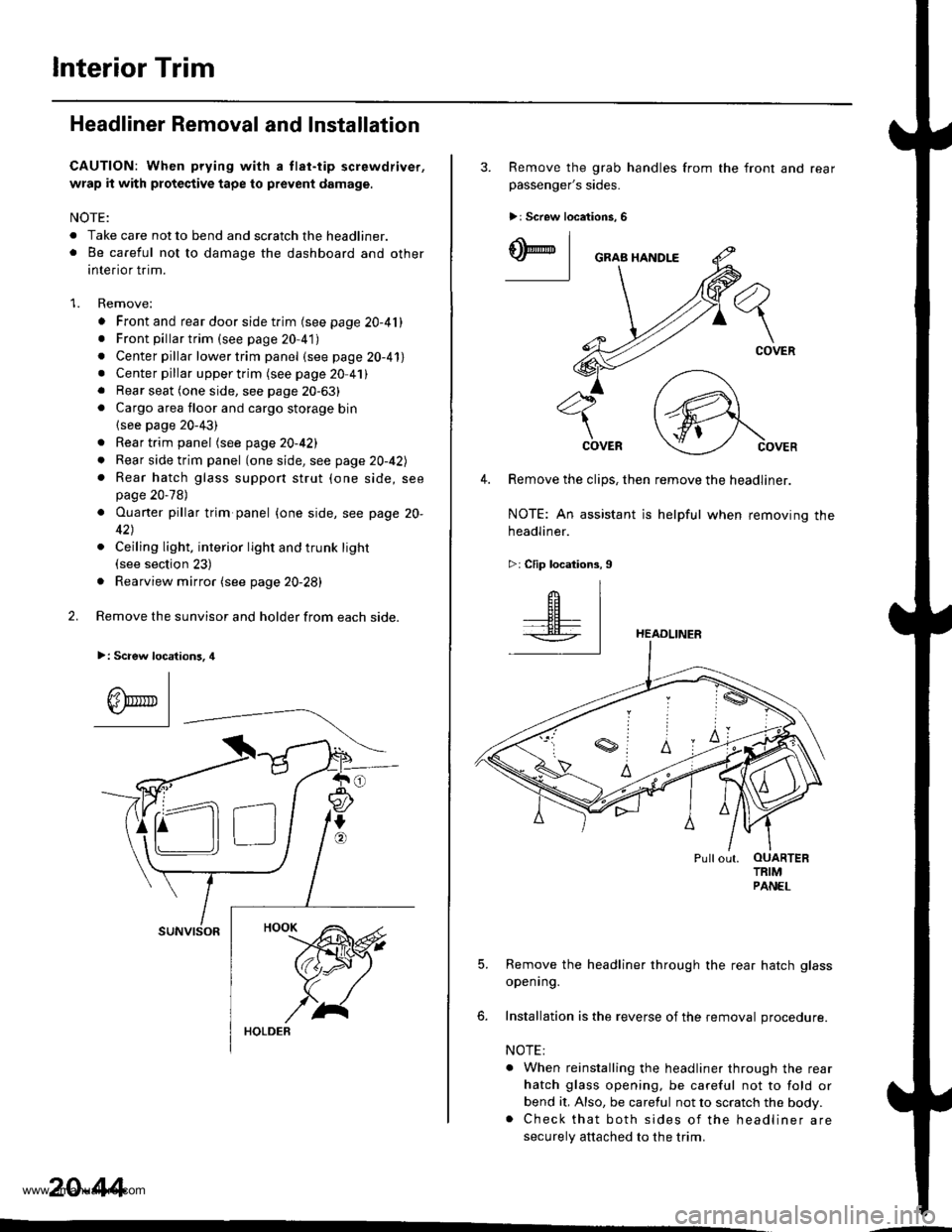
Headliner Removal and Installation
CAUTION: When prying with a tlat-tip screwdriver,
wrap it with protective tape to prevent damage.
NOTE:
. Take care not to bend and scratch the headliner.o Be careful not to damage the dashboard and other
interior trim.
1. Remove:
. Front and rear door side trim (see page 20-41). Front pillartrim (see page 20-41)
. Center pillar lower trim panel (see page 20-41). Center pillar upper trim (see page 20 41). Rear seat (one side, see page 20-63). Cargo area floor and cargo storage bin
{see page 20-43)
. Rear trim panel (see page 20-421
. Rear side trim panel (oneside, see page 20-42l,
. Rear hatch glass support strut (one side, seepage 20-78)
. Ouaner pillar trim panel {one side, see page 20-
42)
. Ceiling light, interior light and trunk light(see section 23)
. Rearview mirror (see page 20-28)
2. Remove the sunvisor and holder from each side.
>: Scaew location3, 4
I
A\"r- |Yr* || -
suNvtsoR
20-44
3. Remove the grab handles from
passenger's sides.
>r Screw locations, 6
the front and rear
ry_l
COVER
4. Remove the clips, then remove the headliner.
NOTE: An assistant is helpful when removing the
headliner.
>: Clip locations,9
HEADLINER
Pullout. OUARTERTRIMPANEL
5. Remove the headliner through the rear hatch glass
openrng.
6. Installation is the reverse of the removal procedure.
NOTE:
. When reinstalling the headliner through the rear
hatch glass opening, be careful not to fold or
bend it, Also, be careful not to scratch the body.. Check that both sides of the headliner are
securely attached to the trim.
www.emanualpro.com
Page 1041 of 1395
Seats
RECUNE ADJUSTER
Front Seat Linkage Disassembly and Reassembly
CAUTION: Put on gloves to protect your hands.
8 x 1 .25 mm22 N.m 12.2 kgl.m,16 tbf.fi)
8 x 1.25 mm22 N.m 12.2 kd-m,16 tbtf0
CROSS BRACE
8 x 1.25 mm22 N.m 12.2 kgl.m,16 tbf.f0
INNER SLIDEADJUSTER
8 x 1.25 mm22 N.rn l.2.2 kgl-m,16 rbr.ft)
CONNECTING WIRETo connect, twist 180".
cRossBRACE
OUTER SLIDEAOJUSTER
Reassembly in the reverse order of disassembly.
NOTE: Grease the moving portions.
20-60
www.emanualpro.com
Page 1043 of 1395
Seats
Front Seat Cover Replacement (cont'dl
Remove the headrest guide, then remove the seat-
Dacx cover.
6. Installation is the reverse of the removal procedure.
NOTE: To prevent wrinkles when installing a seat-
back cover, make sure the material is stretched evenly
over the pad before securing the hook and inside
springs.
Seat cushion cover:
1.Remove the seat cushion (see pages 20-58, 59).
Remove the clips from under the seat cushion. then
loosen the seat cushion cover.
SEATCUSHIONCOVER
20-62
CLIP
3. Pull back the edge of the seat cushion cover all the
way around, then release the clips. and remove the
seat cushion cover.
COVER (pad side)
lnstallation is the reverse of the removal procedure.
NOTE:
. To prevent wrinkles when installing a seat cush-
ion cover. make sure the material is stretched
evenly over the pad before securing the clips.
. Replace the released clips with new ones.
UPHOLSTERY RING PLIERS
lCommercially available)
NEW CUP
SEAT FRAME
www.emanualpro.com
Page 1051 of 1395

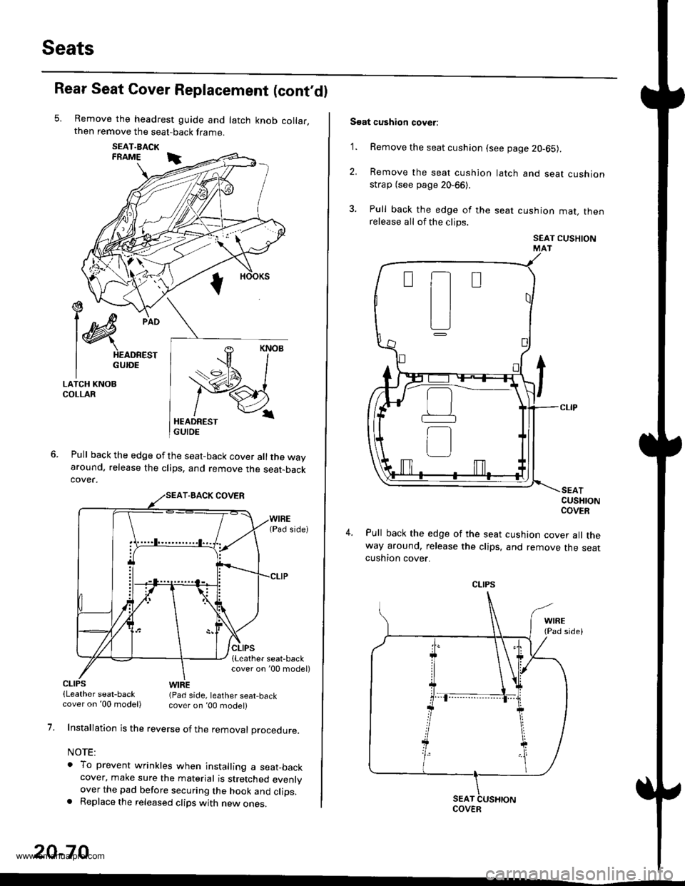
Seats
Rear Seat Cover Replacement (cont'dl
Remove the headrest guide and latch knob collar,then remove the seat-back frame.
SEAT.BACKFRAME i
Pull back the edge of the seat-back cover all the wayaround. release the clips, and remove the seat-backcover.
€ --t)c/
l@
pio
I HEADREST
I GUroE
LATCH KNOBCOLLAR
CLIPS(Leather seat-backWIRE(Pad side, leather seat,back
1.
20-70
cover on '00 model) cover on ,00 model)
Installation is the reverse of the removal procedure.
NOTE:
o To prevent wrinkles when installing a seat_backcover, make sure the material is stretched evenlyover the pad before securing the hook and clips.. Replace the released clips with new ones.
Soat cushion cover:
'1. Remove the seat cushion (see page 20-65).
2. Remove the seat cushion
strap (see page 20-66).
3. Pull back the edge of the
release all of the clips.
latch and seat cushion
seat cushion mat, then
SEAT CUSHIONMAT
CUSHIONCOVER
Pull back the edge of the seat cushion cover all theway around, release the clips, and remove the seatcushton cover.
t-t
tl
L]
CLIPS
COVER
www.emanualpro.com
Page 1052 of 1395
5. Installation is the reverse of the removal procedure.
NOTE:
o To prevent wrinkles when installing a seat cush-
ion cover, make sure the material is stretched
evenly over the pad before securing the clips.
. Replace the released clips with new ones.
UPHOLSTERY FING PUERS(ComE|erciallY available)
WIRE(Pad side)
PAD
20-71
www.emanualpro.com
Page 1054 of 1395
A>, 5 V.2
>: Clip locationsA>, 5 B>.3
lf necessary, remove the front bumper beam, front bumper upper beam and guard bar.
>: Boh locationsc>.6D>,2E>,6
TIE DOWNHOOK
Yl- r
{to/
Installation is the reverse ot the removal procedure.
NOTE:
. Make sure the front bumper engages the front
bumper upper beam securely.
. It necessary, adjust the front bumper upper beam
to obtain the proper gap.
. lf necessary, replace any damaged clips.
Gfu @p;i,li',ll-"-'
TIE.DOWNHOOK
v1
10 x 1.25 mm38 N.rn {3.9 kgf.m,28 rbl.ftl
@,,2
nln-nlznr I
dE6 I #\Er+ | ;lHl= |€ =.=r t:Wl
BEAM
FRONT BUMPEB
20-73
www.emanualpro.com
Page 1055 of 1395
Bumpers
Rear Bumper Removal and Installation
CAUTION: Put on gloves to proteqt your hands.
NOTE:
. An assistant is helpful when removing the rear bumper.. Take care not to scratch the rear bumDer and bodv.
>: Boli, screw locationsa>,2B>,4c>, 10>: Clip locelions, 7
rgfi\\* ffi\\-. 3il;l-'lln*n,..,
WJ/* Y)f t.2tbtftl
.f-.' I
0f'" I trl-l.Kl
-l
BEAR BUMPERSTEP
SIOE MARKERLIGHT CONNECTOFDisconnect.REAR SPLASHGUARD
To body
To body
SIDEMARKERLIGHT
To body
To body
REAR BUMPER
Installation is the reverse of the removal procedure.
NOTE:
. lf necessary, replace any damaged clips.. Make sure the side marker light connectors are plugged in properly.. Make sure the rear bumper engages the side clips on each side securely.
20-74
LIGHT
www.emanualpro.com
Page 1056 of 1395
Hood
Replacement
NOTE:
. An assistant is helpful when removing and installing the hood.
a Take care not to damage the hood and body
. When removing the clips, use a clip remover.
>: Bolt locations, 4
6x1.0mm9.8 N.m {1.0 kgt.m,7.2 tbtfr)
WINDSHIELDWASHER NOZZLES(see page 20-100)
G
{
\HOODHINGEWINDSHIELDWASHER TUBE(see page 20-100)
Installation is the reverse of the removal procedure
NOTE:
. Make sure the hood opens properly and locks securely.
. Adjust the hood alignment.
. Adjust the aim of the windshield washer nozzles (see page 20-102)
HOOD
20-75
www.emanualpro.com