Page 300 of 1395
PGM-FI System
Check for an open in the wires{lAT, SG2lines):1. Turn the ignition switch OFF.2. Connect ECM/PCM connectorterminals C18 and C25 with ajumper wire.3. Turn the ignition switch ON (ll).4. Check the IAT with the scantool.
ls -4'F 1-20"C) or less (or L limitin Honda mode of PGM Testeri or5 V indicated?
Repsir op€n in the wirca batweenthe ECM/PCM 1C18, C25l and theIAT s€nsor.
Substitute a known-good ECM/PCM rnd recheck, lf normal IATis indicated, leplaco the originslECM/PCM.
Intake Air Temperature (lATl Sensor (cont'd)
(From page 11,97)
'l
ECM/PCM CINNECTOR C t3lPl
257II
./ 16171819 202122234 Wp,29c)31
sG2IAT {RED/YELI{GRN/BLK)
JUMPER WIRE
Wire side of fernale terminals
I
1 1-98
www.emanualpro.com
Page 301 of 1395

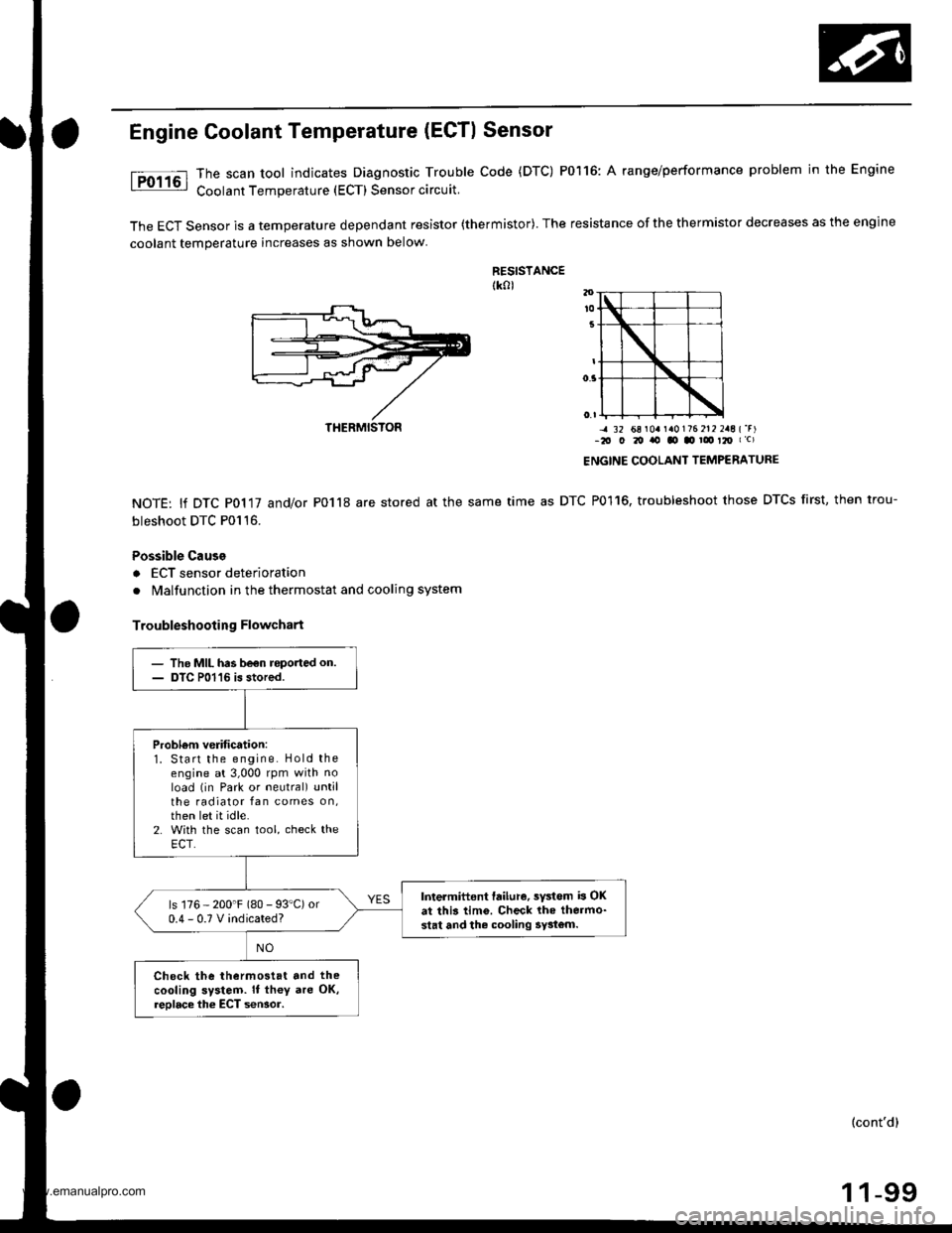
Engine Goolant Temperature (ECTI Sensor
The scan tool indicates Diagnostic Trouble Code (DTC) P0116: A range/performance problem in the Engine
Coolant Temperature (ECT) Sensor circuit.
The ECT Sensor is a temperature dependant resistor (thermistor). The resistance of the thermistor decreases as the engine
coolant temperature increases as shown below
RESISTANCEtk0l
NOTE: lf DTC P0117 and/or P0118 are stored at the same
bleshoot DTC P0116.
Possible Cause
a ECT sensor deterioration
. Malfunction in the thermostat and cooling system
Troubleshooting Flowchart
-4 32 68 r0a r a0176 212 2aE {'r)-2O O 20 ito tO .o ! t2O I c)
ENGINE COOLANT TEMPERATURE
time as DTC P0116, troubleshoot those DTCS first, then trou-
THERMISTON
- The MIL has be€n roported on.- DTC P01'16 is stored.
Probl6m verification:1. Start the engine. Hold theengine at 3,000 rpm with noload (in Park or neutral) untilthe radiator fan comes on,then let it idle.2. With the scan tool, check theECT.
Intermittent failure, sYstem b OKat this tim6. Check lhe thermo-stat and the cooling 5y3tom.
ls 176 - 200'F (80 - 93"C) or0.4-0.TVindicated?
Check the thermostat and the
cooling system. It th€y are OK,reolace the ECT seNor.
(cont'd)
1 1-99
www.emanualpro.com
Page 302 of 1395

PGM-FI System
Engine Coolant Temperature (ECTI Sensor {cont'd)
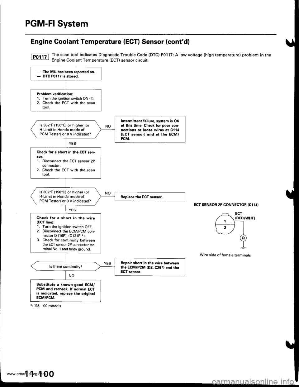
[F011' The.scan tool indicates Diagnostic Trouble Code (DTC) P0117: A low voltage (high temperature) problem in the: Engine Coolant Temperature (ECT) sensor circuit.
ECT SENSOR 2P CONNECTOR {C114I
Wire side of female terminals
- The MIL has been rooortod on.- DTC ml17 is sto.od.
Problem verification:1. Turn the ignition switch ON {ll).2. Check the ECT with the scantool,
Intermittont f.ilure, sysiom is OKat thk time. Check for poor con-nections or loo3e wire3 at C1lil(ECT sensorl and et the ECM/PCM.
ls 302"F (150'C) or higher (or
H Limit in Honda mode otPGM Tester) or 0 V indicated?
Check for a Bhort in the ECT sen-301:'1. Disconnect the ECT sensor 2Pconnefior,2. Check the ECT with the scantool.
ls 302"F (150"C)or higher (or
H-Limit in Honda mode ofPGM Tester) or 0 V indicated?
Check for r shorl in the wirs(EgT linel:1. Turn the ignition switch OFF.2. Disconnect the ECM/PCM con-nector D (16P), (C (31P)*1.3. Check tor continuity betweenthe ECT sensor 2P connectorterminal No. 1 and bodyground.
Repair short in the wir€ betweenthe ECM/FCM (D2, C26rl ,nd th6ECT senaor.
ls there continuity?
Substitute a known-good ECM/PCM and recheck. It normal ECTi! indicatod, replaco the oiiginalECM/PCM.
*:'98 - 00 models
1-1
www.emanualpro.com
Page 304 of 1395
PGM-FI System
Chack lor an open in the wires(ECT, SG2 lines):1. Turn the ignition switch OFF.2. Connect ECM/PCM connectorterminals C18 and C26 with a
3. Turn the ignition switch ON (ll).
4. Check the ECT with the scantool.
ls -4"F (-20"C) or less (or L-Limitin Honda mode of PGM Testerlor5 V indicated?
Ralpair open in tho wir6s b6twe€ntho ECM/PCM 1C18, c26l 6nd thoECT sensor.
Substitute a known-good ECM/PCM and rech.ck. lf normal ECTis indicrted, replace ths originslECM/PCM.
Engine Goolant Temperature (ECTI Sensor (cont'dl
(From page 11 101)
ECM/PCM OONNECTOR C 13lPI
(GRN/BLK)
JUMPER WIRE
Wire side of temale terminals
17I9
,/ 1617't8'1920n
ECT IRED/WHTIsG2
11-102
www.emanualpro.com
Page 306 of 1395
PGM-FI System
(From page 11 103)
ls there approx. 0.5 - 0.9 kO?
Chock for an open or short in theTP sensor:Measure resistance between theTP sensor 3P connector termin-nals No. 2 and No.3 with thethrottle t!lly closed.
ls there approx. 4.5 kO?
Check to. an open in the PCM(TPS linell1. Reconnect the TP sensor 3Pconnector.2. Turn the ignition switch ON (ll).3. Measure voltage betweenPCM connector D (16P) termi-nals D1 and D1l.
Substitute a known-good PCMand recheck. It orescribod volt-age is now available, roplaco theo.iginal PCM.
ls there approx.0.5 V when thethroftle is fully closed andapprox. 4.5 V when the throttleis fully opened?
Repair short in the wire bstweenthe PCM lDl)snd the TP ssnso..
Throttle Position (TP) Sensor (cont'd)
TP SENSOR 3P CONNECTOR
Terminal side of male terminals
PCM CONNECTOR D I16PI
TPS IREO/BLK)SG2 (GRN/BLKI
Wire side ol female terminals
11-104
I
www.emanualpro.com
Page 307 of 1395

'98 - 00 model3:
The MIL has boon reDortod on.DTC m122 b rtorod.
P.oblom veiification:1. Start the engine. Hold theengine at 3,000 rpm with noload (in Park or neutral) untilthe radiator tan comes on,then turn the ignition switchOFF.2. Turn the ignition switch ON lll).3. Check the throttle position
with the scan tool.
ls there approx. 10% when thethrottle is fully closed andapprox. 90% when the throttleis fully opened?
Intarmittent failure. system is OKat thia time. Check for poor con-n€ctions or loolo wires rt C130ITP s.nsorl and.t the ECM/FCM.
Check for an opon or short in thowire {VCC2 linel:1. Turn the ignition switch OFF.2. Disconnect the TP sensor 3Pconnedor,3. Turn the ignition switch ON (ll).
4. Meas! re voltage betweenthe TP s€nsor 3P connector ter-minals No. 1 and No.3.
ls there approx. 5 V?
Check lor an opon in wiro IVCC2linel:Measure voltage between ECM/rcM connector terminals C'18 andc2a.Chock for en op€n or Bhort in TP3an30r:1. Turn the ignition switch OFF.2. At the sensor side, measureresistance between the TPsensor 3P conneclor terminalsNo. 1 and No. 2 with the throt-tle fully closed.
B.psir opon in the wire b€{woontho ECM/PCM {C281 and th6 TP3en!xtt.ls lher€ approx. 5 V?
Subslitute e known-good ECM/PCM .nd r.chock. lf pro3cribedvoltrge iB now rYrilablo, replacath. originll ECM/PCM.
TP SENSOR 3P CONNECTOR {C130}
sG2IGRN/BLKI
vcc2IYEUBLUI
Wire side oI Iemale lerminals
Wire sid6 of temale terminals
Terminal side of male torminals
(cont'd)
1 1-105
ECM/PCM CONNECTOR C (31P}
sG2IGRN/BLKIa-,l 18 sl./|135
/1617lrs]zolzr zzl
232527)gJ lzgi3o sr I
T^vccz {YEL/8LUl
(To page 11-106)
www.emanualpro.com
Page 308 of 1395
PGM-FI System
TP SENSOR 3P CONNECTOR
Terminal side of mal6 terminals
(GRN/BLKI
Wire side ol temale torminals
Throttle Position (TPl Sensor (cont'dl
(From p6ge 11-105)
ls there approx. 0.5 - 0.9 kO?
Chock for rn op€n or 3hort in thoTP sonsorMeasure resistance between theTP sensor 3P connector terminalsNo. 2 and No. 3 with the throttlefully closed.
ls th€re approx. 4.5 k0?
Check lor an open in the ECM/PCM ITPS linel:1. Reconnect the TP sensor con'nector.2. Turn the ignition switch ON {ll).3. Measure voltage betweenECM/PCM connector C (31P)
terminals C18 and C27.
ls thgre 6pprox.0.5 V when thethrottle is Iully closed andapprox.4.5 V when the throttleis lully opened?
Subrtituto . known-good ECM/PCM rnd rocheok. lI pro.cribed
voltaga ia now rvailablc, rcpl.ceth. o.igln.l ECM/PCM.
Raoai. ahort in th€ wira lrltw.anthe ECM/PCM (C181 lnd th€ TP3€n3rot.
ECM/PCM CONNECTOR C {31P}
I37llaI
1617t8 19lm
2327tl l2e3031
TPS IRED/BLK)Lle
{9}
1 1-106
www.emanualpro.com
Page 310 of 1395
PGM-FI System
(From page 11-107)
Check lor an open in the wirc(SG2line):
Measure voltage between ECM/PCM connector C (31P) terminalsC18 and C28.
Ropair open in th€ wire betweonrhe ECM/PCM (Cl81 .nd the TP56nSOl,
ls there approx. 5 V?
Substitute a known-good ECM/PCM and rocheck. lf pre3cribedvoltago is now avaibble, replacetho origin.l ECM/PCM,
Throttle Position (TP) Sensor (cont'dl
ECM/PCM CONNECTOR C {31PI
Wire side of temale terminals
1 1-108
www.emanualpro.com