1998 HONDA CIVIC internal
[x] Cancel search: internalPage 200 of 2189
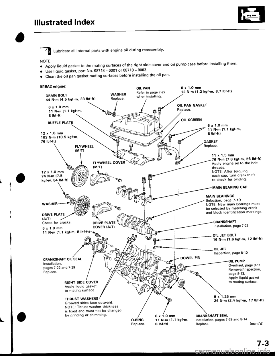
lllustrated Index
I runricate att internal parts with engine oil during reassembly'
NOTE:
o Apply liquid gaskettothe mating surfaces ofthe right side cover and oil pumpcase before installingthem'
. Use liquid gasket, part No 08718-0001 or08718-0003'
. Clean the oil pan gasket mating surfaces betore installing the oil pan
81642 engine:
DRAIN BOLT44 N,m {4.5 kgf'm,33 lbt'ft)
6 x 1.0 mm'11 N.m (1.1 kgI'm,
I tbl.ft)
OIL PANReter to page 7 27when installing.
6 r 1.O mm12 N.m t1.2 kgl'm, 8 7 lbf'lt)
OIL PAN GASKET
BUFFLE PLA
12 x 1.0 mm103 N.m {10.5 kgf'm,
76 tbr.ft)
6 x 1.0 mm11 N.m (1 .1 kgf.m,
8 tbI.fr)
GASKETReplace.FLYWHEEL(M/TI
12 x 1.0 mm
74 N.m (7.5
kof.m, 54 lbf'ft)
1^c{Eb\%^ t*^
*o"rr^--(Wffi
oa*,trto2,.w
FLYWHEEL COVER
IM/T)
DRIVE PLATECOVER (AiT)
11 x 1.5 mm76 N.m (7.9 kgf'm, 56 lbf'ft)
Apply engine oil to the bolt
threads.NOTE: After torqurngeach cap, turn crankshaft
to check for binding.
MAIN EEARING CAP
MAIN BEARINGSSelection, page 7_10
NOTE: New main bearings musl
be selected bY matching crank
and block identification markrngs
CRANKSHAFTInstallation, Page 7'23
OIL JET BOLT16 N.m 11.6 kgf'm, 12 lbl'ft)
OIL JETInspection, Page 8_10
Check for cracks
6x1.0mm11 N.m {1.1 kgf'm, I lbf'ft}
CRANKSHAFT OIL SEAL
Installation,pagesl 22 andl 29
Replace-
DOWEL PINOIL PUMPOverhaul, page 8-'l1Removal/lnspection,page 8-13.Apply liquid gasket
to mating surlace.RIGHT SIDE COVERApply liquid gasket
to mating surface.
THRUST WASHERS8 x 1.25 mm24 N.m {2.4 kgf.m, 17 lbf'ft)Grooved sides face outward
NOTE: Thrusr washer thickness
is tixed and must not be changed
by grinding or shimming
O-RINGReplace
CRANKSHAFT SEAL11 N.m {1.1 kgf'm, lnstallation, pages 7'29 and I 14
a lbt.ltl Heplace. (cont'd)
d#*
Page 201 of 2189

lllustrated Index
(cont'dl
I Luoricate att internal parts with engine oil during reassembly.
NOTE:
' Apply liquid gasket to the mating surfaces ofthe rightside coverand oil pumpcase before installingthem.. Use liquid gasket, part No. 08718 - 0001 or 087,18 _ OOO3.. Clean the oil pan gasket mating surfaces before installing it.
D16Y7 engine:6 x 1.0 mm12 N.m (1.2 kgt.m.8.7 tbf.tr)DRAIN BOLT44 N.m {4.5 kgt.m.33 tbt.ttl
,(
I
I
OIL PAN GASKETFLYWHEEL COVERIM/T)6x 1.0 mm12 N.m ('l .2 kgt.m, 8.7 tbt.trl
OIL PANRefer to page 7-27
Apply liquid gasker tothese points.
Replace.
WASHERReplace.12 x '1.0 mm118 N.m{12.0 kgt.m, 87 tbf.tr}
11 x 1.5 mm51 N.m15.2 kgl.m,38lbtftl
Apply engine oilto the boltthreads.NOTE: After torquingeach cap, turn the crankshaftto check for binding.
MAIN BEARINGSSelection, page 7-10
MAIN BEARING CAP
CRANKSHAFTInstallation, page 7 23
NOTE: New main bearings mustbe selected by matching crankand block identification markings.
6 r 1.0 mm11 N.m {1.1
6 x 1.0 mm11 N.m 11.1
ksI.m, 8 lbt.ft)
OIL SCREEN
kgt.m, 8 lbf.trl
Check for cracks.
CRANKSHAFT OIL SEALInstallation,pages 1 22 a^d 7-29
\:eprace'
GASKETReplace.
6 x 1.O mm11 N.m {1.1 kgt.m,8 rbt.frl
RIGHT SIDE COVERApply liquid gasker1o matrng surface,
OIL PUMPOverhaul, page 8-12Bemoval/lnspection,page 8-13
DOWEL PIN
WASHERSGrooved sides face outward.NOTE: Thrust washer thicknessis fixed and must not be changedby grinding or shimming.
CRANKSHAFT SEAL
l.j"Ji:l"^ pages z.2e --.S)
Replace.
6 x 1.0 mm11 N.m {1.18 tbt.fr)
7-4
BREATHING PORT COVERMOUNT BOLTS6 x 1.0 mm11 N.m {1.1 kgt.m, 8 tbf.fr}Apply liquid gasker tothe boh threads.
DOWEL PIN
Page 203 of 2189

lllustrated Index
(cont'd)
NOTE: New rod bearings must be selected by matching connecting rod assembly and crankshaft(see page 7,11).identification markings
Lubricate all internal parts with engine oil duringreassembtv.
PISTON INSTALLATION DIRECTION:
EXHAUST
4\/=\6\z\
\e/!rqrf/
INTAKE
PISTON RINGSReplacement. page 7-20Measurement, pages 7 20 andj-21Alignment, page 7-21
PISTON PINRemoval, page 7,17Installation, page 7-18Inspection, page 7,19
CONNECTING RODEnd play, page 7-8Selection, page 7,18
CONNECTING RODBEARINGSClearance, page 7 11Selection, page 7-11
CONNECTING ROD BEARING CAPInstallation, page 7-23NOTE: lnstall caps so thebearing recess is on thesame side as the recessin the rod.
PISTONInspectron, page 7-15NOTE: Betore removing the piston, inspect thetop of the cylinder bore for carbon build-up orridge. Bemove ridge if necessary, page 7-13
ENGINE BLOCKCylinder bore inspection, page 7-16Warpage inspection, page 7,'16Cylinder bore honing, page 7,17
Inspect top of each cylinder borefor carbon build-up or ridgebefore removing piston.Remove ridge if necessary, page 7-13
CONNECTING ROD CAP NUT816A2 €ngin6:9 x 0.75 mm{0 N.m (4.1 kgt m, 30 tbf.ftlD16Y5, Dl6Y7. D16Y8 engines:8 x 0.75 mm3l N.m {3.2 kg{.m,23 tbt.fr)Apply engine oiltothe bolt threads.NOTE: After torquing each bearingcap, rotate crankshaft tocheck for binding.
7-6
Page 270 of 2189
!
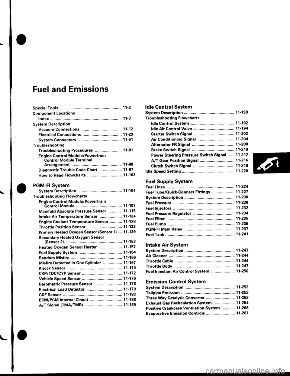
Fuel and Emrsslons
SoecialToofs .....,...."..,. 11-2
Component Locations
lndex ....................., ......... 11-3
Svstem Description
Vacuum Connections ................,,..,.. ......... 11-12
Electrical Connections ...............,.,.,... ....... 11-29
System Connectors ........,.,.,.......................... 1 1-51
Troubleshooting
Troubleshooting Procedures ................. .. 11-81
Engine Control Module/PowertrainControl Module TerminalAfiangement ....,.,..... 11-88
Diagnostic Trouble Code Chart .................,., 11.97
How to Read Flowcharts .,.......................... . 11-103
PGM-Fl System
System Description ...... 11-10,1
Troubleshooting Flowcharts
Engine Control Module/PowertrainContlol Module ........ 11-107
Manitold Absolute Pressure Sensor .....'. . ... 11-115
fntake Air Temperatuie Sensor ..... . . ., . 11'121
Engine Coolant Temperatuae Sensol ........., 11-128
Throttle Position Sensor ...................,........... 11-132
Primary Heated Orygen Sensor (Sensor 1l ... 11-139
Secondary Heated Oxygen Sensor(Sensor 21.................................................... 1 1-153
Heated Oxygen Sensor Heater ...................,. 11-157
Fuel Supply System ...... 11-164
Random Mislire ......., ..11-166
Misfire Detected in One Cylindsr ................. 11-167
Knock Sensor .,.,............ 11-170
CKP/TDC/CYP Sensor ................................... 11'172
Vehicle Speed Sensor ...........,......,...,.,........... 1t-176
Barometric Pressure Sensor ...............,......... I 1-178
Electrical Load Detector,.,,............................ 1 1-179
CKF Sensor .................... 11-183
ECM/PCM Internal Circuit ............................. I 1-188
A/T Signal {TMA/TMBI .................................. I 1-189
ldle Control System
System Doscriplion ............ 11-190
Troubleshooting Flowcharts
ldle Control System ...... 11-192
ldle Air Control Va1ve .................................... I 1-19i1
Starter Switch Signal .................................... 1 1'202
Air Conditioning Signal ................................. 11'201
Ahernator FR Signal .................................... . 1 1-208
BrakeSwitch Signal ..................................... f 1"210
Power Sleering Prossure Switch Signal ......11-212
A/T Gear Position Signal ............................... 11-216
Clutch Swiich Signal ................................-.... 11-214
ldte Speed Setting . .............11-220
Fuel Supply System
Fuel Lines .,...................,.,.,.,11-221
Fuef Tube/Ouick-Connect Fittings ..........,.,........ 11 -227
System Description ....'.... 11-230
Fuel Pressure .......,.,,........... 11-230
Fuef fniectors ......................11-232
Fu€f Pressure Regulator .....,.......................'...,. 11-231
Fuef Fifter ............................11-235
Fuel Pump .............'.......'.... 11-236
PGM-FI Main Relay .............11'237
Fuel Tank ................ ....,...'.'.' 11'211
Intake Air System
System Description ....-.-.....11-243
Air Cfeaner ...........,......."". .11-211
Throttle Cable .....................11-211
Throttfe Body ........ ..'... . . .,.11-211
Fuel Iniestion Air Control System ,.,.,....-........... 11-250
Emission Control System
System Description .-..........11-252
Taifpip€ Emission ...............11-252
Three Way Catafytic Convert€r ............,.,,.,.,.,.... 11 -252
Exhaust Gas Racirculaiion System ...,.,,,,.,.,.,.,,. 11'254
Positive Crankcas€ Ventilation System .... . . .. 11-266
Evaoorative Emission Controls ..................,,..,.,. 11 -267
Page 355 of 2189
Troubleshooting
Troubleshooting Procedures (cont,dl
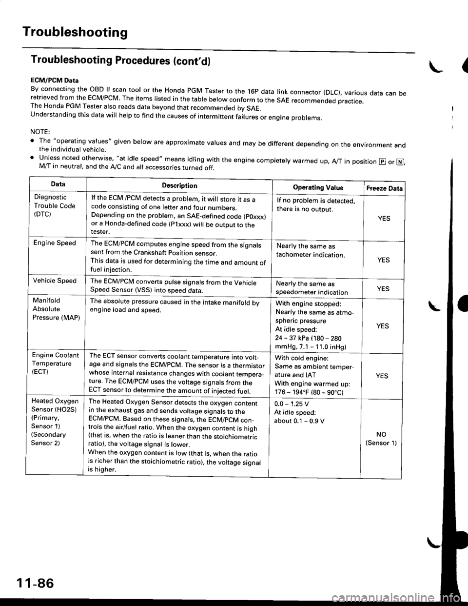
ECM/PCM Data
By connecting the OBD ll scan tool or the Honda pGM Tester to the l6p data link connector (DLC), various data can beretrieved from the EcM/PcM. The items Iisted in the table below conform to the sAE recommended practice.The Honda PGM Tester also reads data beyond that recommended bv SAE.understanding this data wil help to find the causes of intermittent fairures or engine probrems,
NOTE:
' The "operating values" given below are approximate values and may be different depending on the environment andthe individual vehicle.. Unless noted otherwise, "at idle speed,, means idling with the engine completely warmed up, Ay'T in position @ or E],M/T in neutral, and the Ay'C and all accessories turned off.
(
DataDescriptionOperating ValueFreeze Data
Diagnostic
Trouble Code(DTC)
lf the ECM /PCM detects a problem, it will store it as acode consisting of one letter and four numbers.Depending on the problem, an SAE-defined code (poxxx)or a Honda-defined code (Plxxx) will be outDut to therester.
lf no problem is detected,
there is no output.
YES
Engine SpeedThe ECM/PCM computes engine speed from the signalssent from the Crankshaft Position sensor.This data is used for determining the time and amount offuel injection,
Nearly the same as
tachometer indication.YES
Vehicle SpeedThe ECM/PCM converts pulse signals from the VehicleSpeed Sensor (VSS) into speed data.Nearly the same as
speedometer indicationYES
Manifold
Absolute
Pressure {MAP)
The absolute pressure caused in the intake manifold bvengine load and speed.With engine stopped:
Nearly the same as atmo-
spheflc pressure
At idle speed:
24 - 31 kPa (180 - 280
mmHg, 7.1 - 11.0 inHg)
YES
Engine Coolant
Temperature
(ECT)
The ECT sensor converts coolant temperature into volt_age and signals the ECM/PCM. The sensor is a thermistorwhose internal resistance changes with coolant temDera_ture. The ECM/PCM uses the voltage signals from theECT sensor to determine the amount of iniected fuel.
With cold engine:
Same as ambient temper,
ature and IAT
With engine warmed up:
176 - 194.F (80 - 90.C)
YES
Heated Oxygen
Sensor {HO2S)(Primary,
Sensor 1)(Secondary
Sensor 2)
The Heated Oxygen Sensor detects the oxygen contentin the exhaust gas and sends voltage signals to theECI\4/PCM. Based on these signats, the ECM/pCM con_trols the airlfuel ratio. When the oxygen content is high(that is, when the ratio is leaner than the stoichiometricratio), the voltage signal is lower.When the oxygen content is low (that is, when the ratiois richer than the stoichiometric ratio), the voltage signalis higher.
0.0 - 1.25 V
At idle speed:
about 0.1 - 0.9 V
NO(Sensor 1)
1 1-86
Page 356 of 2189
DataDescriotion
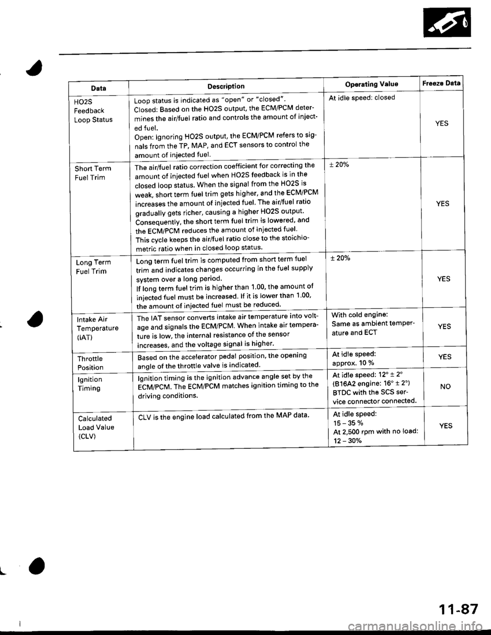
Loop status is indicated as "open" or "closed"'
Closed: Based on the HO2S output, the ECM/PCM deter-
mines the airlfuel ratio and controls the amount of inject-
ed fuel.
Open: lgnoring HO2S output, the ECM/PCM refers to sig-
nals from the TP, MAP, and ECT sensors to control the
amount of injected fuel.
The air/fuel ratio correction coefficient for correcting the
amount ot injected fuel when H02S feedback is in the
closed loop status When the signal from the HO2S is
weak, short term fuel trim gets higher, and the ECM/PCM
increases the amount of injected fuel The airlfuel ratio
gradually gets richer, causing a higher HO2S output
Consequently, the short term fuel trim is lowered, and
the ECMiPCM reduces the amount of injected fuel
This cvcle keeps the airlfuel ratio close to the stoichio-
metric ratio when in closed loop status'
Operating ValueF eeza Data
HO2S
Feedback
Loop Status
At idle speed: closed
YES
Short Term
Fuel Trim
! 20%
YES
Long Term
Fuel Trim
Long term fuel trim is computed from shon term fuel
trim and indicates changes occurring in the fuel supply
svstem over a long Period
lf long term fuel trim is higher than 1.00, the amount of
injecGd fuel must be increased. lf it is lower than 1 00'
the amount of injected fuel must be reduced'
! 20%
YES
lntake Air
Temperature
{IAT)
The IAT sensor converts intake air temperature into volt-
age and signals the ECM/PCM. When intake air tempera-
ture is low, the internal resistance of the sensor
increases. and the voltaqe signal is higher'
With cold engine:
Same as ambient temPer'
ature and ECTYES
At idle speed:
approx. 10 %YESThrottle
Position
Based on the accelerator pedal position, the open'ng
angle of the throttle valve is indicated
lgnition
Timing
lgnition timing is the ignition advance angle set by the
gCV/eCV. tn" gCU/PCM matches ignition timing to the
driving conditions.
CLV is the engine load calculated from the MAP data'
At idle speed: 12'i 2'
(81642 engine: 16" t 2")
BTDC with the SCS ser-
vice connector connected.
NO
Calculated
Load Value
{CLV)
At idle speed:
15-35%
At 2.500 rpm with no load:
12 - 30%
YES
ro
11-87
Page 408 of 2189
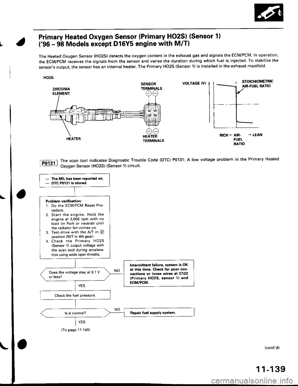
Primary Heated Oxygen Sensor {Primary HO2SI (Sensor 1)
t('96 - 98 Models except Dl6Y5 engine with M/Tl
The Heated Oxygen Sensor (HO2S) detects the oxygen content in the exhaust gas and signals the ECM/PCM. In operation,
the ECM/PCM receives the sjgnals from the sensor and varies the duration during which fuel is injected To stabilize the
sensor,s output, the sensor has an internal heater. The Primary HO2S (Sensor 1) is installed in the exhaust manifold.
HO2S:
VOLTAGE {VI
The scan tool indicates Diagnostic Trouble Code (DTC) P0131; A low voltage
Oxygen Sensor (H02S) (Sensor 1) circuit.
R|cH-AIR- - LEANFUELRANO
problem in the Primary Heated
SENSOR
ztRcoNlA
The MIL has be€n teported on.DTC P0131 is siorcd.
Problom verificalion:1. Do the ECM/PCM Reset Pro'
cedure.2. Start the engine. Hold theengine at 3,000 rpm with noload (in Park or neutral) untilthe radiator fan comes on,3. Test-drive with the A/T in Eposition (M/T in 4th gear)
4. Check the Primary HO2S(Sensor 1) output voltage with
the scan tool during accelera-
tion using wide open throttle.
lntcrmift€nt failura, 3Y3tem is OKat this tims. Check for Poor con-nections or loo3e wi.o3 at C123(Primlry HO2S, 3sn3or 1) and
ECM/PCM,
(To page 1I-140)
{cont'd)
1 1-139
Page 681 of 2189
Description
The automatic transmission is a 3-element torque converter and a dual-shaft electronically controlled unit which provides
4 soeeds forward and 1 reverse.
Torque Convertel, Geats, and Clutches
The torque converter consists of a pump, turbine and stator, assembled in a single unit. They are connected to the engine
crankshaft so they turn together as a unit as the engine turns. Around the outside of the torque converter is a ring gear
which meshes with the starter pinion when the engine is being started. The entire torque converter assembly seryes as a
flywheel while transmiuing power to the transmission mainshaft.
The transmission has two parallel shafts: the mainshaft and the countershaft. The mainshaft is in Iine with the engine
crankshaft. The mainshaft includes the 1st, 2nd and 4th clutches, gears tor 2nd, 4th, reverse and lst (3rd gear is integral
with the mainshaft, while the reverse gear is integral with the 4th gear). The countershaft includes the 3rd clutch, and
gears for 3rd,2nd, 4th, reverse. 1st and park. The gears on the mainshaft are in constant mesh with those on the counter-
shaft. When certain combinations of gears in transmission are engaged by clutches. power is transmitted from the main-
shaft to the countershaft to provide E, ld, E, and E positions.
Electronic Control
The electronic control svstem consists of the Powertrain Control Module {PCM), sensors, a linear solenoid and four
solenojd valves. Shifting and lock-up are electronically controlled for comtonable driving under all conditions. The PCM is
located below the dashboard, under the front lower panel on the passenger's side
Hydraulic Control
The valve bodies include the main vatve body, the secondary valve body, the regulator valve body, the servo body and the
lock-up valve body through the respective separator plates, They are bolted on the torque converter housang
The main valve body contains the manual valve, the 1-2 shift valve. the 2nd orifice control valve, the CPB {Clutch Pressure
Back-up) valve, the modulator valve. the servo control valve, the relief valve, and ATF pump gears The secondary valve
body contains the 2-3 shift valve. the 3-4 shift valve, the 3-4 orifice control valve, the 4th exhaust valve and the CPC (Clutch
pressure Control) valve. The regulator valve body contains the pressure regulator valve, the torque converter check valve,
the cooler relief valve, and the lock-up control valve. The servo body contains the servo valve which is integrated with the
reverse shift fork, and the accumulators. The lock-up valve body contains the lock-up shift valve and the lock-up timing
valve. The linear solenoid and the shift control solenoid valve Ay'B are bolted on the outside of the transmission housing,
and the lock-up control solenoid valve Ay'B is bolted on the outside of the torque converter housing. Fluid from regulator
passes through the manual valve to the various control valves. The clutches receive fluid from their respective teed pipes
or internal hydraulic circuit.
Shift Control Mechanism
Input from various sensors located throughout the car determines which shift control solenoid valve the PCM will activate
Activating a shift control solenoid valve changes modulator pressure, causing a shift valve to move. This pressurizes a line
to one of the clutches, engaging that clutch and its corresponding gear, The shift control solenoid valves A and B are con-
trolled by the PCM.
Lock-up Mechanism
In ,Dt1 position, in 3rd and 4th. and in E position in 3rd, pressurized fluid is drained from the back of the torque converter
through a fluid passage, causing the lock-up piston to be held against the torque converter cover. As this takes place, the
mainshaft rotates at the same as the engine crankshaft. Together with hydraulic control, the PCM optimizes the timing of
the lock-up mechanism. The lock-up valves control the range of lock-up according to lock-up control solenoid valves A and
B, and linear solenoid. When lock-up control solenoid valves A and B activate, the modulator pressure changes The lock-
up control solenoid valves A and B and the linear solenoid are controlled by the PCM.
(cont'd)
14-3