Page 3 of 2189
ll
General Information
Ghassis and Paint Codes ....................... 1-2
ldentification Number Locations ......... 1-32
Warning/Caution Label Locations ....... 1-33
Under-hood Emissions
Control Label .......... ....... 1-37
Lift and Support Points
Lift and Safety Stands ....................... 1-41
Floor Jack ....................... 1-42
Towing ......... 1-43
Page 43 of 2189
Lift and SupPort Points
L,O
Lift and SafetY Stands
t!ffi when heavv rear components such as suspension' fuel tank' spare tire' hatch' and trunk lid are to be
-aEremoved, place additional wetght Inihe luggage arga before hoisting. when substantial weight is lemoved from the rear
of the vehicls. the center of gravity may change and can cause the vehicle to tip tolward on the hoisi
NOTE:
. Since each tire/wheel assembly weighs approximately 30 lbs (14 kg)' placing the front wheels in the luggage area can
assist with the weight distribution
. Use the same support points to suppon the vehicle on safety stands'
Place the lift blocks as shown.
Raise the hoist a lew inches (centrmeters) and rock the vehicle to be sure it is firmly supported'
Raise the hoist to full height, and inspect lift points for solid support
1.
2.
3.
REAR SUPPORT POINT
1-41
Page 44 of 2189
Lift and Support Points
Floor Jack
Apply the parking brake and block the wheets thatare not being lifted.
When lifting the rear of the vehicle, put the gearshiftlever in reverse (Automatic transmission/Cw in Eposition).
Raise the vehicle high enough to insert the safetystands.
Adjust and place the safety stands so the vehiclewill be approxlmately level, then lower the vehicleonto them.
FRONT:
Always use safety stands whon working on or undelany vehicle that is supported by only a iack.Never attempt to use a bumper jack for lifting orsupporting the vehicle.
t,1.
REAR:
1-42
LIFT PLA
4.
Center the jacking
bracket in the middleof the iack lift platform.
Center the iackbracket in the middleof the jack lift ptatform.
-,-_
LIFT PLATFORM
L,
Page 45 of 2189

Towing
lf the vehicle needs to be towed, call a professional tow-
ing service. Never tow the vehicle behind another vehi
cle with iust a rope or chain lt is very dangerous'
Emergency Towing
There are three popular methods of towing a vehicle:
Flat-bed Equipment - The operator loads the vehicle on
the back of a truck. This is the best way of transporting the
vehicle.
Wheel Lift Equipment - The tow truck uses t\ivo pivoting
arms that go under the tires {front or rear} and lifts them
off the ground. The other two wheels remain on the
ground.
Sling-type Equipment - The tow truck uses metal cables
with hooks on the ends. These hooks go around parts of
the frame or suspension, and the cables lift that end of
the vehicle off the ground The vehicle's suspension and
body can be seriously damaged if this method of towing
is attemDted.
lf the vehicle cannot be transported by flat-bed. it should
be towed with the front wheels off the ground lf due to
damage, the vehicle must be towed with the front
wheels on the ground, do the following:
lvlanual Transmission and CW
. Release the parking brake
. Shift the transmission to neutral (CW to E position)'
Automatic Transmission
. Release the Parking brake.
. Sta rt the engine.
. Shift to LDll position, then E position.
. Turn oif the engine
CAUTION;
o lmploper towing preparation will damage ihe tfans-
mission. Follow the above procedute exaqtly lf you
cannot shift the tlansmission or start the engino
laulomatic transmissionl, yout vehicle must be trans-
ported on a flat-bed.
. lt is best to tow the vehicle no farther than 50 mil€s
(80 km), and ksop thE speed below 35 mph (55 km/hl
. Trying to lift 01 tow your vehicle by tho bump€F will
caus€ setious damagg. Ths bumpers are not dEigned
to supportthe vshicle's weigh.
tJO
1-43
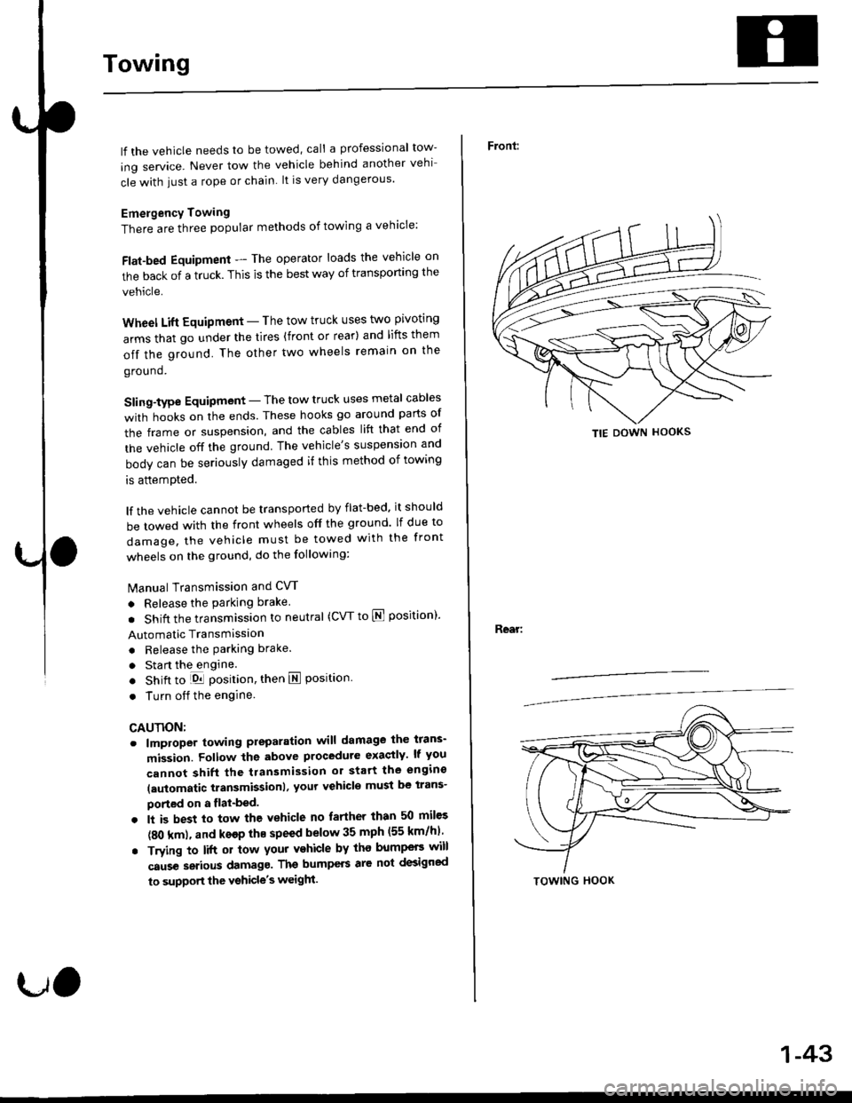
Front:
Rear:
TIE DOWN HOOKS
TOWING HOOK
Page 51 of 2189

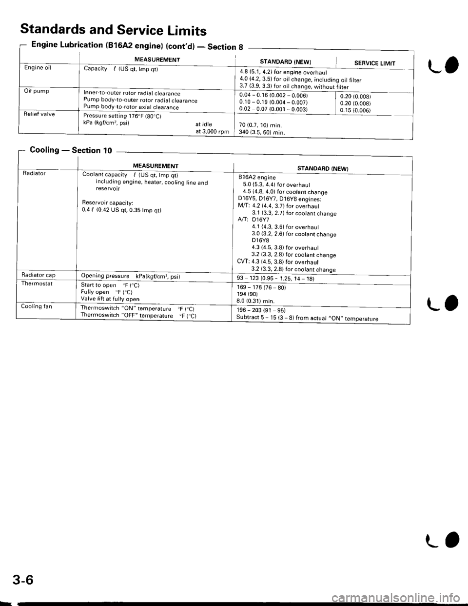
MEASUREMENTSTANDARD INFWIEngine oilCapacityf (uS qt, lmp qt)
Inner-to outer rotor radial clearancePump body-to outer rotor radialclearancePump body to-rotor axial clearance
4.8 (5.1, 4.2) for eng;ne overhaul4.0 (4.2, 3.5) for oil change, ;ncludin3.7 (3.9.3 3)for dil .h,nde '^,irh^,,rg oilfilter
Oil pump0.04 - 0.16 {0.002 - 0.006)0.10 - 0.19 (0.004-0.007)0.02 0.07 10.001 ,0.003)
0.20 (0.008)
0.20 {0.008)0 15 {O OO6iRelief valvePressure setting 176"F (80.C)kPa (kgflcm,, psi) at;dteat 3,000 rpm70 (0.7, 10) min.340 (3.5,50) min.
Standards and Service Limits
Engine Lubrication (B16A2 engine) (cont,d) - Section 8
Cooling - Section 10
L,
L.
MEASUREMENTSTANOARO {NEW)RadratorCoolant capacity t 1US qt, tmp qt)including engine, heater, cooling line andreservotr
Beservoir capacity:0.4 f {0.42 US qt, 0.35 lmp qt)
81642 engine5.0 {5.3, 4.4) for overhaul4.5 (4.8, 4.0) for cootant changeD16Y5, D16Y7, D16Y8 engines:M/T: 4.2 (4.4, 3.7)for overhaul3.1 (3.3, 2.7) for coolant changeA"/T: 016Y74.1 (4.3, 3.6) for overhaul3.0 (3.2, 2.6) for cootant changeDl6Y84.3 {4.5, 3.8)for overhaul3.2 (3.3, 2.8) for cootant changeCW: 4.3 (4.5,3.8)for overhaul3.2 (3.3, 2.8)for cootant chanqeRadiator capOpeningpressure kPa(kgl/cm,,psi)
Start to open .F (.C)Fully open "F ('C)Valve lift at fulty open
93 123 (0.95- 1.25, 14 18)
169 - 176 (76 80)194 (90)
8.0 (0.31)min.
196 - 203 191 95)Subtract 5 - 15 {3 - 8) from actual ,,ON,, temperature
Thermostat
Cooling fanThermoswilch 'ON" temperature F r.C,Thermoswitch "OFF' lemperature .F ( C)
L
3-6
L,
Page 140 of 2189

13. Remove the upper radiator hose' heater hose and
water bYPass hose
WATEREYPASSHOSEUPPERRADIATORHOSE
14.
HEATERHOSE
Remove the engine wire harness connectors and
wire harness clamps from the cylinder head and the
intake manifold.
o Four fuel injector connectors
. Engine coolant temperature (ECT) sensor con-
nector
a
a
a
ECT switch connector
ECT gauge sending unit connector
Throttle position sensor connector
Manitold absolute pressure (MAP) sensor con-
nector
Primary heated oxygen sensor (primary HO2S)
connector
Secondary heated oxygen sensor (secondary
HO2S) connector (D16Y7 engine)
Exhaust gas recirculation (EGR) valve lift sensor
connector (D16Y5 engine)
. VTEC solenoid valve connector (Dl6Y5, D16Y8
engrnes)
. VTEC pressure switch connector (D16Y5. D16Y8
engrnes,
. ldle air control (lAC) valve connector
15.Remove the spark plug caps and distributor from
the cylinder head.
Remove the uPPer bracket.
NOTE:
. Use a jack to support the engine before the
upper bracket is removed.
. Make sure to place a cushion between the oil
pan and the jack.
12 x 1.25 mm
74 N.m {7.5 kgf m.
sil lbl.ftl
UPPERBRACKET
'17. Remove the cylinder head cover'
CYLINDERHEAD COVER
(cont'd)
6-29
Page 147 of 2189

Gamshaft
Inspection
NOTE:
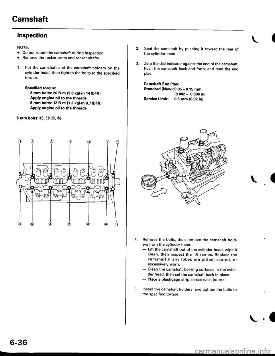
. Do not rotate the camshaft during inspection.. Remove the rocker arms and rocker shafts.
1. Put the camshaft and the camshaft holders on thecylinder head. then tighten the bolts to the specified
toroue.
Spocified torqu€:
8 mm bolts; 20 N.m (2.0 kgf.m t4 lbf.ft)Apply engin6 oil to tho throads,
6 mm bohs: t2 N.m (1.2 kgf'm 8.7 tbf.ft)
Apply oogine oil to the thleads.
6 mm bolts: @, @ @, @
6-36
E
\(
2. Seat the camshaft by pushing it toward the rear ofthe cylinder head.
3, Zero the dial indicator against the end ofthe camshaft.Push the camshaft back and fonh, and read the endptav.
Camshaft End Play:
Standard {New):0.05 - 0.15 mm
10.002 - 0.006 inl
Sorvice Limit 0.5 mm (0.02 in,
I
5.
Remove the bolts, then remove the camshaft hold-ers from the cylinder head.- Lift the camshaft out of the cylinder head, wipe itclean, then inspect the liit ramps, Replace thecamshaft if any lobes are pitted. scored, orexcessively worn,- Clean the camshaft bearing surfaces in the cylin-der head, then set the camshaft back in place.- Place a plastigage strip across each Iournal.
Install the camshaft holders, and tighten the bolts tothe soecified toroue.
\,l
Page 185 of 2189

Camshafts
Inspection
NOTE:
. Do not rotate the camshaft during inspection.
. Removg the rocker arms and rocker shafts.
'L Put the camshafts and camshaft holders on the cylin-
der head. and then tighten the bolts to the specified
torque.
Specified Torque:
O -@: 8 mm botts 27 N.m {2.8 kgf.m,20 lbt'ft)
Apply engine oil to the threads,
O - @: 6 mm bolts 9.8 N.m (1.0 kgf m, 7.2 lbf'ft)
Seat the camshaft by pushing it toward the distribu-
tor end of the cylinder head.
Zero the dial indicator against the end of the distrib-
utor drive. then push the camshaft back and fonh
and read the end play.
Camshaft End Play:
Standard {New}: 0.05 - 0.15 mm
{0.002 - 0.006 inl
Service limil: 0.5 mm (0.02 in)
ooooooo
ooooo
\-
4.Remove the bolts. then remove the camshaft hold-
ers from the cylinder head.
- Lift the camshaft out of the cylinder head, wipe
clean, then inspect the lift ramps. Replace the
camshaft if lobes are pitted, scored, or excessively
- Clean the camshaft bearing surfaces in the cylin
der head, then set the camshaft back in place,
- Insert a plastigage strip across each iournal.
Put the camshaft on the cylinder head. then install
the camshaft holders, and then tighten the bolts to
the specified torque as shown in the left column on
this page.
Remove the camshaft holders, then measure the
widest portion of the plastigage on each journal.
Camshaft -to-Hold€1 Oil Clearsnce:
Standard {Newl: 0.050 - 0.089 mm
{0.002 - 0.004 inl
S6rvice Limit: 0.15 mm 10,006 inl
(cont'd)
6-75
PLASTIGAGE STRIP