Page 530 of 2189

\JExhaust Gas Recirculation System (D16Y5 engine with M/T)
M/T:
EGR VALVE 6P CONNECTOB (C14'rl
G10lIBLK}
1
a
PNK
IE.EGRI
Wi16 side of male terminals
I
sG2{GRN/BLK}
vcc2{YEL/BLU)
- Th6 MIL ha3 b€on reponed on.- DTC Pl,{tl is 3tored.
Prcblem verification:1. Do the ECM Reset Procedure.
2. Connect the SCS service con_nector.3. Start the engine. Hold the
engine at 3,000 rpm with no
load (transmission in neutral)
untilthe radiator fan comes on.
4. Drive the vehicle on the road
for approx. 10 minutes. Try to
keep the engine speed in the
1,700 - 2,500 rpm range.
lnlermittont tailure, svalem is OK
at thi3 tim6. Check foi Poor con'
nections or looso wiro3 at Cl/K
IEGR valvsl and ECM.
ls DTC P1491 indicated?
Check tor a malfunction in the
EGR valv6:1. Turn the ignition switch OFF.
2. Disconnect the EGR valve 6P
connector.3. Stanthe engine and let it idle
4. Measure voltage between the
EGR valve 6P connector termi'
nals No.4and No.6.
Check the EGR valve:1. Turn the ignition switch OFF2. Turn the ignition switch ON lll).3. Measure voltage between theEGR valve 6P connector termi
nals No.2 and No.3.
ls there battery voltage?
Substitute a known-good ECM
and recheck. It symptom/indica_tion goes away, replace th€ origi-
nal ECM.
ls there approx.5V?
(To page 11-262)
Page 540 of 2189

\J
\
,96 D16Y5 engine,,96 D16r,gngino,,96 Dt6Y8 engine {3edan)' 37 D16Y5 engino..97 D16r, engine {coupe: KA, Kc mod-
els. sedan: KA, KC, KL {DX} models. hatchback: all modols}''97 Dl6Y8 ongine (s€dan: KA' KC mod€lsl:
The scan tool indicates Diagnostic Trouble code (DTC) P0441: Evaporative Emission (EVAP) control system
insufficient purge flow.
Description
By monitoring the purge line vacuum with the MAP sensor, the ECM/PCM can detect insufficient EVAP control system
purge flow.
Possible Cau3e
. EVAP Purge Control Solenoid Valve
. EVAP Purge Control Solenoid Valve Circuit
. EVAP Control Canister
. Vacuum Lines
. ECM/PCM
Troubl93hooting Flowchart
Wire side of femaleterminals
EVAP PURGE CONTROI-sottNotD vALvE 2P
CoNNECTOR (Cl1al
r-+-r
I'l'l
lG-ro.*l'rr"r
O)
Y
(cont'd)
11-271
- The MIL has bsGn.eportad on.- DTC milal k rtored.
Pioblem vsrificJtion:1. Start the engine. Hold the
engine at 3,000 rPm with no
load {in Park or noutral) until
the radiator fan comes on.
2. Do the ECM/PCM Reset Proce'
dure,3. Connect the SCS service con-
nector.4. Test-drive under following con-
ditions on the road- Without any electrical load- A/T in E or E Position(M/T in 3rd-sth gear)- Engine sPeed betweon
1,200 - 2.400 rpm.- Decelerate {rom 50 mph (80
knl/h)to 15 mph (24 km/h)lntormittont lailuro, sFtorn b OK
at thi. timo. Ch€ck tor Poor con'
ncction3 or looac wir.3 at C144
{EVAP purgo control tolonoid
vrtv.l .nd ECir/FCttl.
ls DTC P0441 indicatod?
Ch.ck fo. !n op€n in the wiro l|(illinel:1. Turn the ignition switch OFF.
2. Disconnect the EVAP Purgecontrol solenoid valve 2P con_
neclor,3. Turn the ignition switch ON (ll)
4. Measur€ voltage between bodyground and the EVAP Purgecontrol solenoid valve 2P con-
nector terminal No 1.
Rop.ir opor in tho wir6 b€two€n
the EVAP purgo codtiol tolonoid
v.lvo rnd tho No 15 ALIERNA'
TOR SP SENSOR 17.5 A)lu.o.
{To page 11-272)
Page 574 of 2189

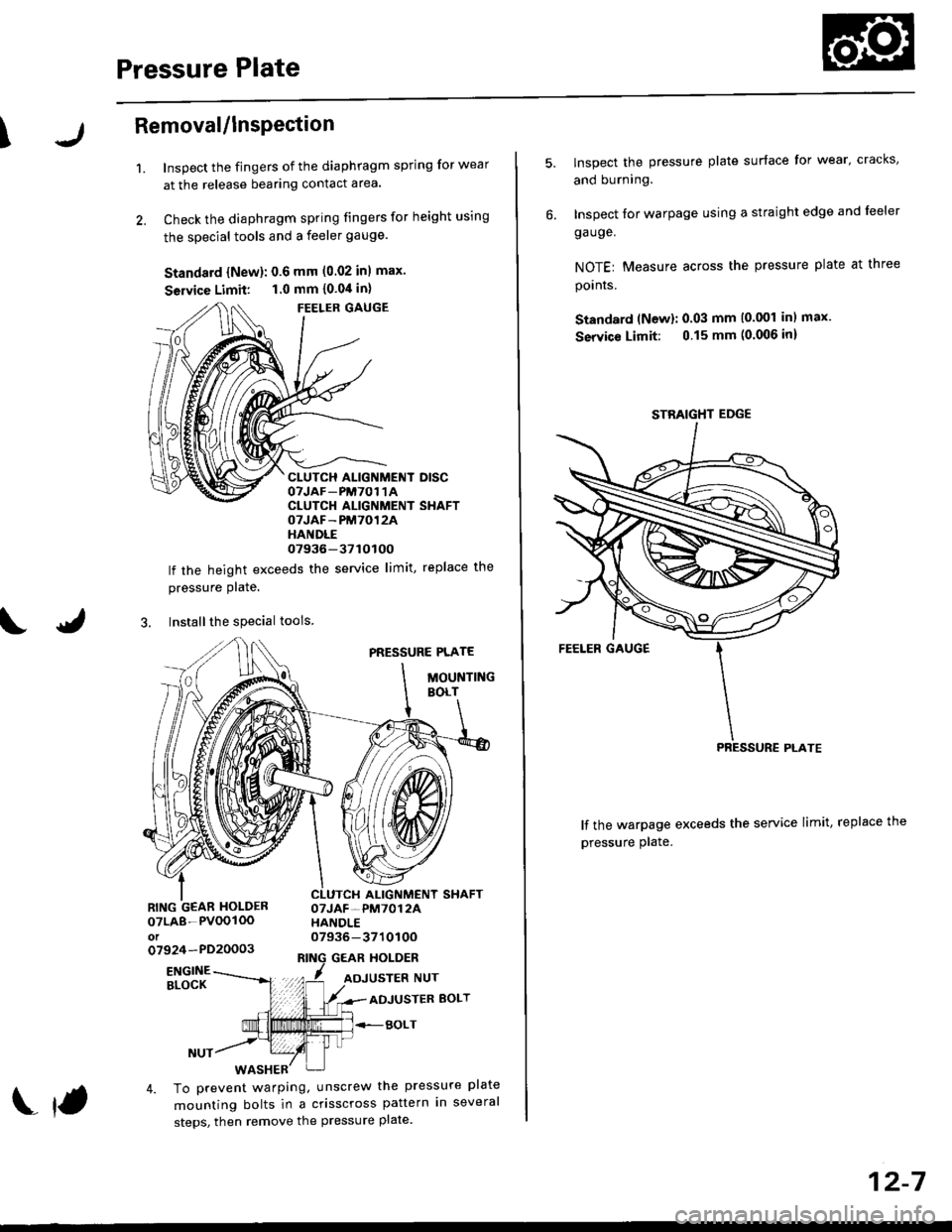
Pressure Plate
\Removal/lnsPection
1.Inspect the fingers of the diaphragm spring for wear
at the release bearing contact area.
Check the diaphragm spring fingers for height using
the special tools and a feeler gauge.
Standard {New}: 0.6 mm (0.02 inl max.
Seruice Limit: 1.0 mm {0.04 in}
FEELER GAUGE
CLUTCH ALIGNMENT DISCOTJAF_PM7O1 1ACLUTCH ALIGNMENT SHAFTOTJAF-PM7012AHANDLE07936-37tOtOO
lf the height exceeds the service limit, replace the
pressure Plate.
3. Installthe special tools
PRESSURE PLATE
MOUNTINGBOLT
ALIGNMENT SHAFTOTJAF-PM7012AHANDLE07936-371010Oo7924-PD20003GEAR HOLDER
07LA8-PVOOIOOot
ENGINEBLOCKADJUSTER BOLT
BOLT
4. To prevent warping, unscrew the pressure plate
mounting bolts in a crisscross pattern in several
steps, then remove the pressure plate.
f
12-7
lnspect the pressure plate surface for wear' cracks,
and burning.
Inspect for warpage using a straight edge and leeler
ga uge.
NOTEr Measure across the pressure plate at three
pornrs.
Standard (Newl: 0.03 mm (0.001 inl max.
Service Limit: 0.15 mm (0.006 inl
lf the warpage exceeds the service limit, replace the
pressure plate.
STBAIGHT EDGE
Page 575 of 2189
Clutch Disc
RemovaUlnspection
2.
'1. Remove the clutch disc and special tools.
CLUTCH
CLUTCH ALIGNMENT SHAFToTJAF-pM7012A xltori07936-3710100
Inspect lining of the clutch disc for signs of slipping
or oil. lf it is burned black or oil soaked, replace it.
Measure the clutch disc thickness.
Clulch Disc Thickness:
Standard (Now): 8.5 - 9.1 mm (0.33 - 0.36 in)
Servic€ Limit: 5.5 mm (0.22 inl
CLUTCH
lf the thickness is less than the service limit. .eolacethe clutch disc.
12-8
U
4. Measure the depth from the lining surface to therivets, on both sides.
Rivet Depth:
Standard lNewl: 1.3 - 1.9 mm {0.05 - 0.07 in} min.
Service Limit: 0.2 mm (0.01 in)
lf the depth is less than the service limit, replace the
clutch disc.
CLUTCH DISC
Page 576 of 2189

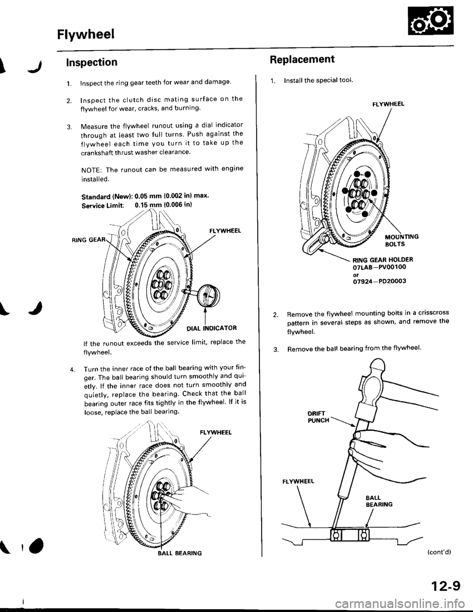
Flywheel
\Inspection
1.
2.
3.
Inspect the ring gear teeth for wear and damage
Inspect the clutch disc mating surface on the
flywheel for wear, cracks, and burning.
Measure the flywheel runout using a dial indicator
through at least two full turns Push against the
flywheel each time you turn it to take up the
crankshaft thrust washer clearance.
NOTE: The runout can be measured with engine
installed.
Standard (New): 0.05 mm (0.002 inl max.
Service Limit: 0.15 mm {0.006 in)
FLYWHEEL
OIAL INOICATOR
FLYWHEEL
lf the runout exceeds the service limit. replace the
flywheel.
Turn the inner race o{ the ball bearing with your tin-
ger. The ball bearing should turn smoothly and qui
etly. lf the inner race does not turn smoothly and
quietly, replace the bearing. Check that the ball
bearing outer race fits tightly in the flywheel. lf it is
loose. replace the ball bearing
IJ
4.
BALL BEARING tO
Replacement
1. Installthe special tool.
MOUNTINGBOLTS
RITIG GEAR HOLDER
oTLAB-PV00100oto7924-PD20003
2.Remove the flywheel mounting bolts in a crisscross
pattern in several steps as shown, and remove the
flywheel,
Remove the ball bearing from the flywheel
(cont'dl
12-9
FLYWHEEL
t\
m\J
Page 593 of 2189

Reverse Shift Holder
)
Glearance Inspection
1.Measure the clearance between the reverse shift
fork and sth/reverse shift piece pin.
Standard: 0.05 - 0.35 mm 10.002 - 0.01,1 inl
Service Limit 0.5 mm (0.02 in)
lf the clearances are more than the service limit.
measure the widths of the groove in the reverse
shifi fork.
Standard: 7.05 - 7.25 mm (0.278 - 0.285 inl
lf the widths of the grooves are not within the
standard, replace the reverse shift holder with a
new one.
lf the width of the grooves are within the stan-
dard, replace the sth/reverse shift piece with a
new one,
\
t
REVERSE
REVERSE SHIFT HOLDER
3. Measure the clearance between the reverse idler
gear and the reverse shift fork.
Standard: 0.5- 1.1 mm {0.02 - 0.0,1in)
Service Limii: 1.8 mm 10.07 inl
REVERSE IDLER GEAR
lf the clgarances is more than thg service limit, mea-
sure the width of the reverse shift fork.
Standlrd: 12.7 - 13.0 mm {0.5110 - 0.512 in}
lf the width is not within the standard, replace
the reverse shift holder with a new one.
lf the width is within the standard, replace the
revsrse idler gear with a new one.
REV€RSE SHIFT FORK
REVERSE SHIFT FORK
REVERSE SHIFT HOLOER
13-13
Page 596 of 2189

Mainshaft Assembly
Clearance Inspection
NOTE: lf replacement is required, always replace the
synchro sleeve and hub as a set.
1. Measure the clearance between 2nd and 3rd gears,
Standard: 0.06 - 0.21 mm 10.002 - 0.008 in)
Service Limit: 0.33 mm (0.013 inl
2ND GEAR
3RO GEAR
lf the clearance is more than the service limit. mea-
sure the thickness of 3rd gear,
Standard: 3O.22 - 3O.27 mm
{1.190 - 1.192 in}
Servica Limit: 30.15 mm (1.187 inl
lf the thickness of 3rd gear is less than the ser-
vice limit, replace 3rd gear with a new one.
lf the thickness of 3rd gear is within the service
limit, replace the 3rdl4th synchro hub with a new
one.
/ -J-il -)frl"-
TI
Hl I
3RD GEAR
13-16
3. Measure the clearance between 4th gear and thespacer collar.
Standard: 0.06 - 0.19 mm 10.002 - 0.007 in)
Service Limit: 0.31 mm 10.012 in)
+
4TH GEAR
INDICATOR
If
-r ''==f{'
5TH GEAR
lf the clearance is more than the service limit, mea-
sure distance @ on the spacer collar.
Standard: ?2.V. - 22.86 mm
10.8!t8 - 0.900 in)
Sorvica Limii: 22.81 mm {0.8t8 inl
4TH GEARSIDE
SPACERCOLLAR
lf distanc€ @ is less than the service limit, replace
the spacer collar with a new one,
lf distance @ is within the service limit, measure
the thickness of 4th gear.
Standard: 30.12 - 30.17 mm(1.186 - 1.188 inl
Servic6 Limh: 30.05 mm (1.1&l inl
4TH GEAR
lf the thickness of 4th gear is less than the ser-vice limit, replace 4th gear with a new one.
lf the thickness of 4th gear is within the service
limit, replace the 3rdl4th svnchro hub with a newone,
di
Page 597 of 2189

T
6. Measure the clearance between the spacer collar
and sth gear.
Standard: 0.06 - 0.19 mm 10.002 - 0.007 inl
Service Limit: 0.31 mm (0.012 inl
4TH GEAR
DIALINDICATOR
I
-<=q,
7.
5TH GEAR
lf the clearance is more than the service limit, mea-
sure distance @ on the spacer coilar
Standard: 23.53 - 23.56 mm
10.926 - 0.928 in)
Sowice Limit 23.51 mm {0.926 in}
SPACERCOLLAR
sTH GEARSIDE
lf distance @ is less than the service limit, replace
the spacer collar with a new one,
lf distance @ is within the service limit, measure
thickness of 5th gear.
Siandatd:28.1:2 - 28.17 mm
11.119 - 1.121 in)
Servica Limit: 28.35 mm (1.116 inl
sTH GEAR
lf the thickness of 5th gear is less than the ser-
vice limit, replace sth Oear with a new one.
lf the thickness of sth gear is within the service
limit, replace the 5th synchro hub with a new
one.
Disassembly
1. Remove the ball bearing using a bearing puller as
shown.
BEARING PULLER(Commercially
availablel
CAUTION: Remov€ ths synchro hubs using a press
and steel blocks as shown. Us€ of a iaw-type pullel
can caus€ damage lo the gear teeih.
Support 4th gear on steel blocks. and press the
mainshaft out of the sth svnchro hub as shown.
{cont'd)
13-17