Page 1939 of 2189
Horn
- '96-'97 Models
UNDER.HOODFUSE/RELAYBOX
c353PHOTOs
See PowerOistribution,pag610-13.""^T.!,-
HORNRELAYPHA|O 58
c214
vtEw21
BLU/FEO
1
VHT/qRN
I1
WHT/qRN
: :i-I:::--li i ! !'-'! fevtess
! a;fi."*
,,lr--J I::.-------J. , STEREO RAOIO TUNER
| | vtEw 68
HORN
l
h: c4o1PHQ|A 57
c430
Sse CruiseControl
Vehicles pre-wired ---lor accessorysecurity system
BLU
GBY
------- J
- -.! STEERINGWHEEL
6 g c411
| _vtEw 60
a,---li
cnv I
18 A C516
sEcuRtwSYSTEMCONNECTOR(oPTroN)PHO|O 73VEW 5A
40
Page 1941 of 2189
Horn
- '99-'00 Models
FUSE 52HORI,SfOP LTt5a
UNDER.HOODFUSE/RELAYBOX
HORNRELAY
2
BIU/FED
Ior
GRY
.,1 ,
J---a-----r---O
i ;l i ;,1...,' r--1 : SECUR|TY:ll:sYsrEM,ia,coNNEcroR' ! ! (oPrloN), L--J , i!,o!o 73, KEYLESS I vlEw 58
: DooR LocK withi coNTRoL Kevless, UNIT EntryI PHOIO 134I vtEw 75
i o.--------;
:T:' cnvl :
i"l ii ri-'--.| coMBtNATtoN
: lrft ! !',f,11" I' | | puotozz :', l--J vttw u ;
i--- Er""pt ex.ooer ----j
c214
v|EW21
c430PHOTO 65
Vehicles pre-wired foraccessory security system
STEERINGWHEEL
CABLEREEL
.l
I
I
I
ISee CruiseControl
GRY
ELU
I
a\
I
GRY
HORN
---------^1
niffil"a!m"
40-2
Page 1945 of 2189

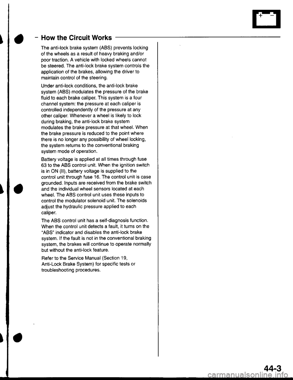
- How the Circuit Works
The anti-lock brake system (ABS) prevents locking
of the wheels as a result of heavy braking and/or
poor lraction. A vehicle with locked wheels cannot
be steered. The anti-lock brake system controls the
application of the brakes, allowing the driver to
maintain control of the steering.
Under anti-lock conditions, the antilock brake
system (ABS) modulates the pressure of the brake
tluid to each brake caliper. This system is a four
channel system: the pressure at each caliper is
controlled independently of the pressure al any
other caliper. Whenever a wheel is likely to lock
dunng braking, the anti-lock brake system
modulates the brake oressure at that wheel. When
the brake pressure is reduced to the point where
there is no longer any possibility of wheel locking,
the system returns to the conventional braking
system mode of operation.
Battery voltage is applied at all times through fuse
63 to the ABS control unit. When the ignition switch
is in ON (ll), battery voltage is supplied to the
control unit through fuse 16. The control unit is case
grounded. Inputs are received from the brake switch
and the individual wheel sensors located at each
wheel. The ABS control unit uses these inputs to
control the modulator solenoid unit. The solenoids
adjust the hydraulic pressure applied to each
calioer.
The ABS control unit has a self-diagnosis function.
When the control unit detects a fault, it turns on the"ABS" indicator and disables the anti-lock brake
system. lf the fault is not in the conventional braking
system, the brakes will continue to operate normally
but without the anti-lock feature.
Refer to the Service Manual (Section '19,
Anti-Lock Brake System) for specific tests or
troubleshooting procedures.
44-3
Page 2168 of 2189

)\
) -,
.'
'1: With shift-up indicator or cruise control system ('96-'97 models)
With cruise control system ('98-'00 models)
.2: '96198 models.3: '99-'00 models
c5o9 csrr c510 c515
13 1c517
DISHAOABD w|REIIARNESS
Connector
or
Terminal
Number of
Cavities/
Color
LocationConnects toNotes
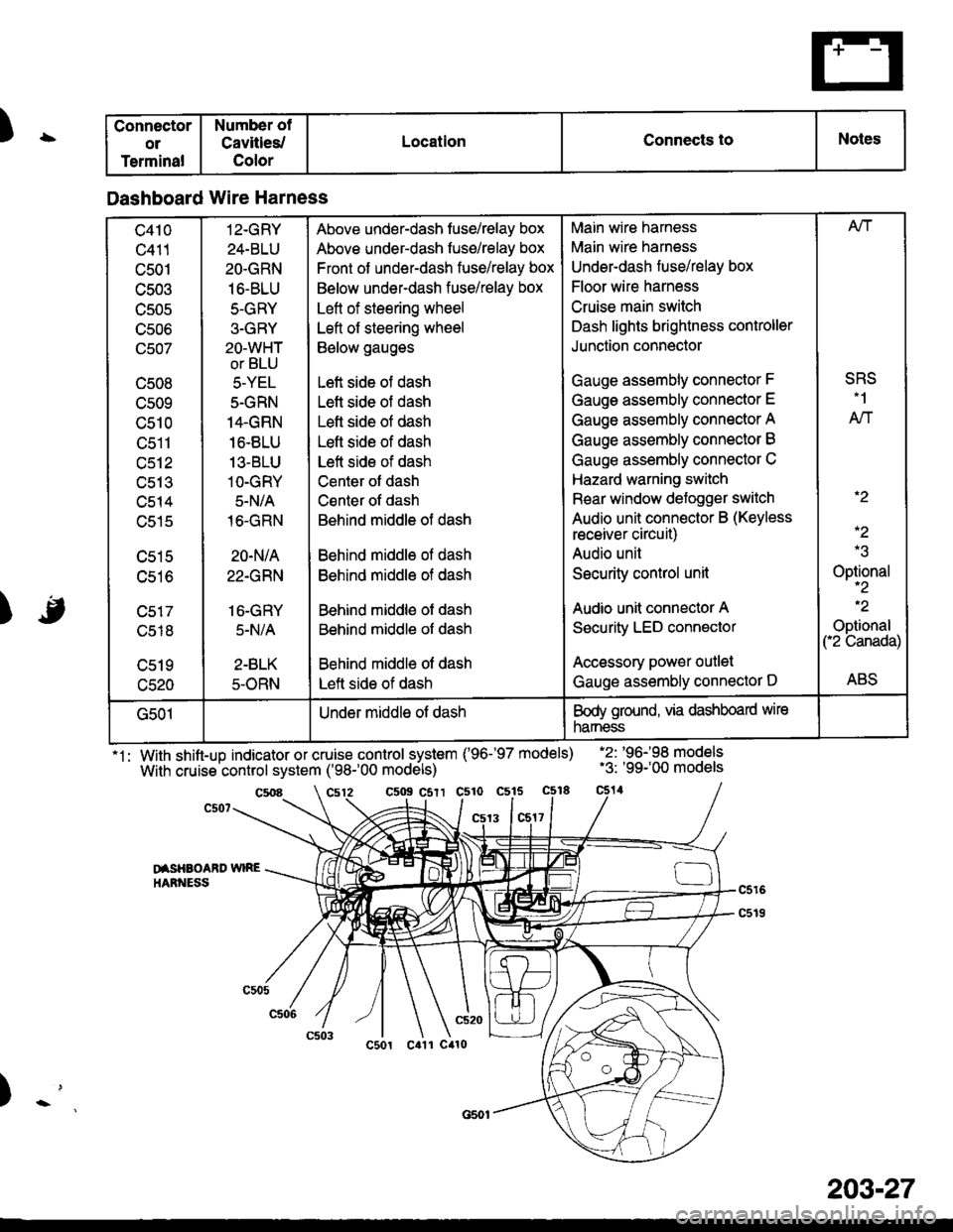
Dashboard Wire Harness
c410
c411
c501
c503
TJJUC
UCUO
(Jcu/
c508
cs09
c510
tJctl
c512
uc t.t
c514
c515
c516
c518
c520
12-GRY
24-BLU
2O.GRN
16-BLU
5-GRY
3-GRY
2O-WHT
or BLU
5-YEL
5-GRN
14.GRN
16.8LU
13-BLU
1O-GRY
5-N/A
16-GRN
20-N/A
22.GRN
16-GRY
5.N/A
2-BLK
5-ORN
Above under-dash fuse/relay box
Above under-dash fuse/relay box
Front of under-dash fuse/relay box
Below under-dash fuse/relay box
Left of steering wheel
Left of steering wheel
Below gauges
Left side of dash
Lett side of dash
Left side of dash
Lefl side of dash
Left side of dash
Center ot dash
Csnter of dash
Behind middle of dash
Behind middle ol dash
Behind middle of dash
Behind middle of dash
Behind middle of dash
Behind middle of dash
Left side of dash
Main wire harness
Main wire harness
Underdash fuse/relay box
Floor wire harness
Cruise main switch
Dash lights brightness controller
Junction connector
Gauge assembly connector F
Gauge assembly connector E
Gauge assembly connector A
Gauge assembly connector B
Gauge assembly connector C
Hazard warning switch
Rear window defogger switch
Audio unit connector B (Keyless
receiver circuit)
Audio unil
Security control unit
Audio unit connector A
Security LED connector
Accessory power outlet
Gauge assembly connector D
Afi
SRS.1
AN
.2
-2
Optional-2
.2
Optional("2 Canada)
ABS
G501Under middle of dashBody ground, via dashboard wire
narness
203-27
Page 2181 of 2189

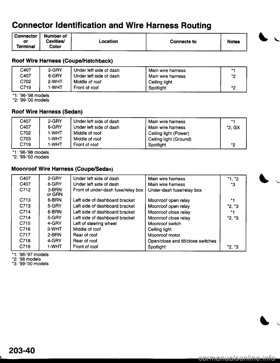
Connector ldentification and Wire Harness Routing
Connector
or
Terminal
Number of
Cavities/
Color
LocationConnects toNotes
Roof Wire Harness (Coupe/Hatchback)
c407
c407
c702
c719
2-GRY
6-GRY
2-WHT
1-WHT
Under lett side of dash
Under left side of dash
Middle of roof
Front of roof
Main wire harness
Main wire harness
Ceiling light
Spotlight
.2
'l : '96-'98 models'2: '99-'00 models
Rool Wire Harness (Sedan)
.1 : '96-'98 models.2: '99100 models
Moonroof Wire Harness (Coupe/Sedanl
*1: '96'97 models'2: '98 models"3: '99r00 models
c407
c407
c702
c703
c719
2-GRY
6-GRY
1-WHT
1-WHT
1-WHT
Under left side of dash
Under left side of dash
Middle of roof
Middle of roof
Front of roof
Main wire harn€ss
Main wire hamess
Ceiling light (Power)
Ceiling light (Ground)
Spotlight
"1
-2, GX
.2
c407
c407
c712
c713
c713
c715
u/ to
c717
c718
c719
2.GRY
6-GRY
3-BRN
or GRN
6-BRN
5-GRY
6.8RN
5-GRY
4-GRY
3-WHT
2-BRN
4-GRY
1-WHT
Under left side of dash
Under left side of dash
Front of under-dash fuse/relay box
Left side of dashboard bracket
Left side of dashboard bracket
Left side of dashboard bracket
Lett side of dashboard bracket
Left of steering wheel
Middle of roof
Rear of roof
R€ar of root
Front of roof
Main wire harness
Main wire harness
Undsr-dash fuse/relay box
Moonroof open relay
Moonroot open relay
Moonrool closa relay
Moonroof close relay
Moonroot switch
Ceiling light
Moonroof motor
Open/close and tiluclose switches
Spotlight
.3
'1
'2,.3
-1
'2,'3
'2,.3
203-40