Page 509 of 2189
Fuel Supply System
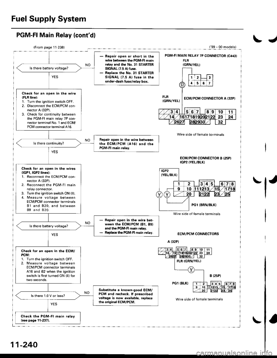
- Repair op€n or short in thewir€ betlveen the PGM-FI mainrelay and the No. 31 STARTERSIGNAL 17.5 A) fuse.- RoDlace the No. 31 STARTERSIGNAL {7,5 Al tuse in theunder-dash luse/rolay box.
ls there battery voltage?
Check tor an open in the wire(FLR linel:1. Turn the ignition switch OFF.2. Disconnect the ECM/PCM con-nector A (32P).
3. Check for continuity betweenthe PGM-FI main relay 7P con-nector terminal No. 1 and ECM/PCM connector terminal A16.
Repair open in the wir6 botweenthe ECM/PCM (A161 and rhePGM-FI main relay.
Check for an open in the wires{lGPl, lGP2 line3):1. Reconnect the ECM/PCM con-nector A {32P).2. Reconnect the PGM-Fl mainrelay connector.3. Turn the ignition switch ON (ll).
4. Measure voltage betweenECN4/PCM connector terminals81 and 820, and betweenBg and 820.
- Repair open in the wire bet-ween th. ECM/PCM (81, Bg)snd the PGM-F main rolay.- Roplace th€ PGM-FI main relav.
Chock tor an open in th6 ECM/PCM:1. Turn the ignition switch OFF.2. Measure vo ltage betweenECM/PCM connector terminalsA16 and 82 when the ignitionswitch is first turned ON lll) for
Sub3titute . known-good ECM/PCM and rochock. lf prescribedvohege is now available, replacethe original ECM/PCM.
ls there 1.0 V or less?
Chock the PGM-Fl m.in r6lay{see p.ge 11-2371.
PGM-FI Main Relay (cont'd)
_._(9x . qq -gqerll _
PGM.FI MAIN FELAY 7P CONNECTOR {C4€}FLR
ECM/PCM CONNECTORS
A (32P1
Wire side ot female terminals
Wire side of fem6le terminals
ECM/PCM CONNECTOR B {25PIIGP2 {YEL/BLKI
IGRN/YEL}
IGP2(YEL/BLKI
Wire side of female terminals
11-240
IJ
'l'
Page 510 of 2189
IFuelTank
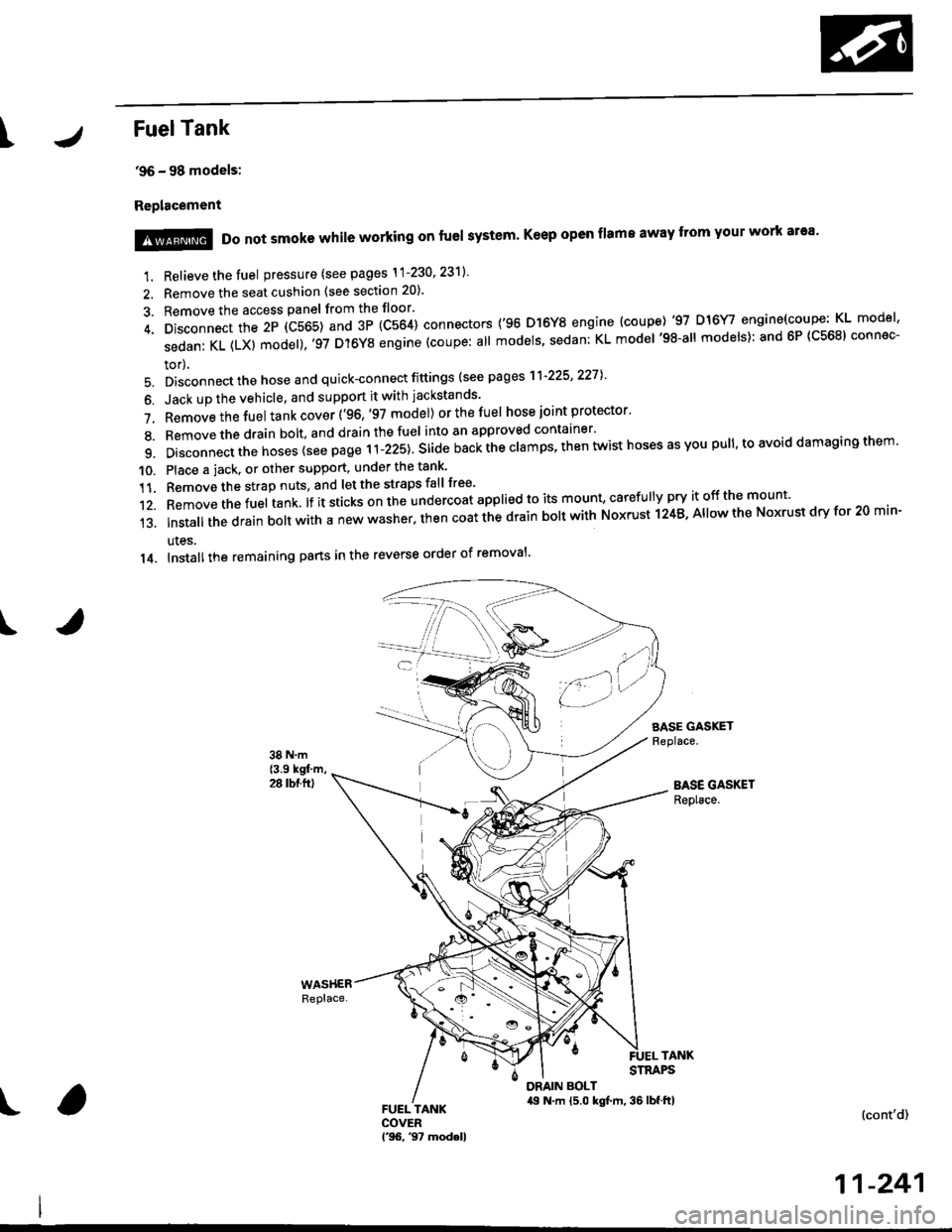
'96 - 98 models:
Replacement
I
1. Relieve the fuel pressure (see pages \1-230' 23'll'
2. Remove the seat cushion (see section 20).
3. Remove the access panel from the floor'
4. Disconnect the 2P (C565) and 3P (C564) connectors ('96 D]6Y8 engine (coupe) '97 D16Y/ engine(coupe: KL model'
sedanKL(LX)model).'97D'l6YSengine(coupe:allmodels'sedan:KLmodel'98-allmodels):and6P(C568)connec-
tor),
5. Disconnect the hose and quick-connect fittings (see pag es'l'l-225' 2271
6. Jack up the vehicle, and support it with jackstands'
7. Removethefuel tank cover ('96,'97 model) orthefuel hose joint protector'
8. Bemovethedrain bolt,and drainthefuel into an approved container'
9. Disconnect the hoses {see page r i-izst. Sria" nu"i ihe clamps, then twist hoses as you pull, to avoid damaging them'
10. Place a jack. or other support, under the tank'
11. Remove the strap nuts, and let the straps fall free'
12. Removethefuel tank lf it sticks on the undercoat applied to its mount' caref u lly pry it off the mount'
13.|nsta||thedrainbo|twithanewwasher.thencoatthedrainbo|twithNoxrustl24B,A||owtheNoxrustdryfor20min-
ules.
14. Installthe remaining pans in the reverse order of removal'
SASE GASKETReplace.
BASE GASKETReplace.
!@@ Do not smoke while working on fuel system' Keep open flame away from your work ar'a'
TANKSTRAPS
DRAIN BOLT,19 N.m {5.0 kgt m, 36 lbf.ftl(cont'd)
11-241
Page 511 of 2189
Fuel Supply System
Fuel Tank {cont'dl
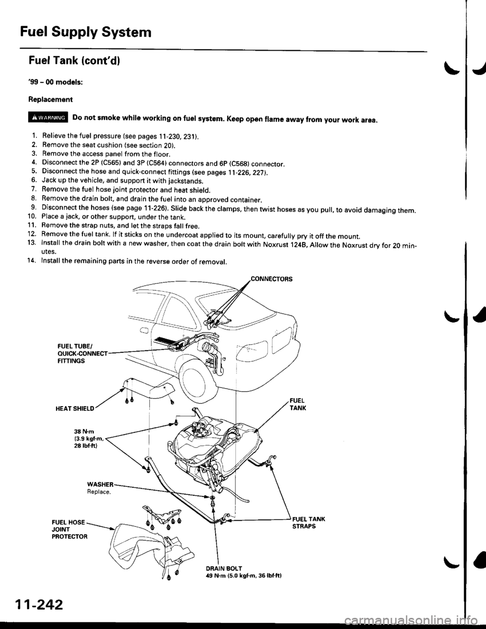
39 - (xt models:
Replac6ment
o
@ Do not smoke whire working on fuer system. Ke€p open frama away trom your work area.
1. Relievethefuel pressure (see pages 11-230,23'll.
2. Remove the seat cushion lsee section 2O).3, Remove the access panel fromthefloor.
4. Disconnectthe2P (C565) and3P(CS64) connectors and 6p (C569) connecror.5. Disconnect the hose and quick-connect fiftings (see pages 1l-226,22j),6. Jack up the vehicle, and support it with jackstands.
7. Removethefuel hose joint protector and heat shield.8. Removethedrain bolt. and drainthefuel intoan aporoved container.9 Disconnect the hoses (see page 11-226). Slide back the clamps. then twist hoses as you pull, to avoid damagtng rnem.10. Place a jack, or other support, under the tank,11. Remove the strap nuts, and let the straps fallfree,'12. Removethefuel tank. lf itsticks onthe undercoat applied to its mount, carefully pry itoffthe mount.13. Install thedfain boltwith a new washer. then coat the d rain bolt with Noxrust 124B,Allowthe Nox.ust drv for 20 min-utes.
14. Installthe remaining parts in the reverse order of removal,
Replace.
DRAIN BOLT,19 N.m (5.0 kgf.m, 36lbf.ft)
11-242
Page 579 of 2189
Release Bearing
Installation
NOTE: Use only Super High Temp Urea Grease(P/N 08798 - 9002).
1. With the release fork slid between the release bear-
ing pawls, install the release bearing on the main-
shaft while inserting the release fork through the
hole in the clutch housing.
RELEASE FORK BOLT12 x 'l .25 mm
tP/N 0a79a-90021O.3-0.9 s 10.01 -O.03 ozl
Align the detent of the release fork with the release
fork bolt, then press the release fork over the
release fork bolt sequarely.
-Gr08798-9002)
2.
12-12
IJ
3. Move the release fork right and left to make surethat it fits properly against the release bearing, and
that the release bearing slides smoothly.
4. Install the release fork boot; make sure the bootseals around the release fork and clutch housino.
Page 581 of 2189
\
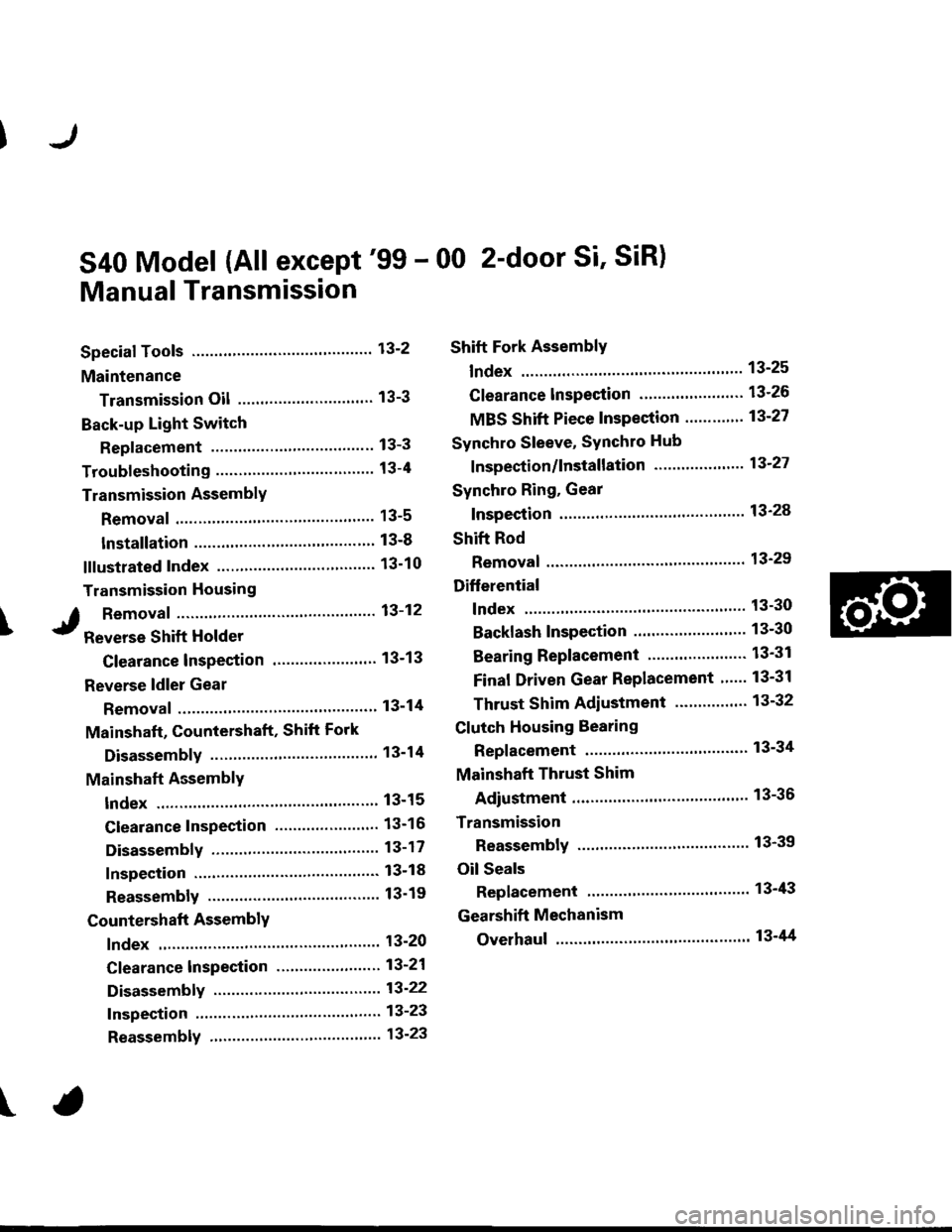
S40 Model (All except'99 - 00 2-door Si' SiR)
Manual Transmission
Special Tools ..'.......... 13-2
Maintenance
Transmission Oil .............................. 13-3
Back-up Light Switch
Replacement ......... 13-3
Troubleshooting '....... 13-4
Transmission AssemblY
Removal ................. 13-5
lnstallation ............. 13-8
lllustrated Index ...............'........."........ 13-10
Transmission Housing
I Removaf .."""""""' 13-12
J R"rr"r"" Shift Holder
Clearance lnspection ....................... 13-13
Reverse ldler Gear
Removal ....'.........." 13-14
Mainshaft, Countershaft, Shift Fork
Disassembly ......'... 13-14
Mainshaft AcsemblY
Index ............... ....... 13-15
Clearance Inspection ..'.................... 13-16
Disassembly .......... 13-17
Inspection ....'......... 13-18
Reassembly ........... 13-19
Countershaft AssemblY
lndex ................ ...... 13-20
Clearance lnspection ."..........'......." 13-21
Disassembly ..."""' 13-22
Inspection .............. 13-23
Reassembly ..'.""... 13-23
Shift Fork AssemblY
lndex ............... ."'... 13-25
Clearance lnspection ."......."........'.. 13'26
MBS Shift Piece Inspection ....-.....'.. 13'27
Synchro Sleeve, Synchro Hub
f nspection/lnstallation .......'...... ".... 13'27
Synchro Ring, Gear
Inspection '....'..".... 13'28
Shift Rod
Removal .'......".""" 13'29
Differential
lndex ......."'...... .'."' 13-30
Backlash Inspection ..........."......."... 13-30
Bearing Beplacement'.............'.".... 13'31
Final Driven Gear Replacement '..... 13-31
Thrust Shim Adiustment ..."........... 13-32
Clutch Housing Bearing
Replacement .......'. 13-34
Mainshaft Thrust Shim
Adiustment '....'..".. 13-36
Transmission
Reassembly ........... 13-39
Oil Seals
Replacement ......... 13-43
Gearshift Mechanism
Overhaul ................ 13-44
\
Page 582 of 2189
Special Tools
Ref. No. I Tool NumbetDescription(Xy I Page Reference
o
@
o.@
!'5,
@
o
@6
@
@
@(3
OTGAJ PG2O11O
OTGAJ PG2012O
07GAJ - PG20130
07736 - A010004
07746 - 0010300
07746 - 0010400
07746 - 0030100
07746 - 0030300
07746 - 0030400
07749 - 0010000
07JAD - PH80101
07JAD - PH80200
07947 - 6110501 or
07947 - 6110500
Mainshaft Holder
Co lla r
Mainshaft Base
Adjustable Bearing Puller, 25 - 40 mm
Attachment. 42 x 47 mm
Attachment,52 x 55 mm
Driver, 40 mm LD.
Attachment, 30 mm I.D.
Attachment, 3S mm LD.
Driver
Driver Attachment
Pilot. 26 x 30 mm
Seal Driver Attachment
1 13-38
1 13-37
1 I 13-37
1 13-34,35
1 13-34.35
1 13-34,35
1 | 13-19,24
31,32
1 13-19,24
1 13-19,24
r I t3-34,35, 43
1 13-43
1 13,43
1 I 13-43
* Must be used with commercially-available 3/8"-j6 Slide Hammer.
oaaal
\91o
aif!
o
ly tr
IvI
Page 583 of 2189
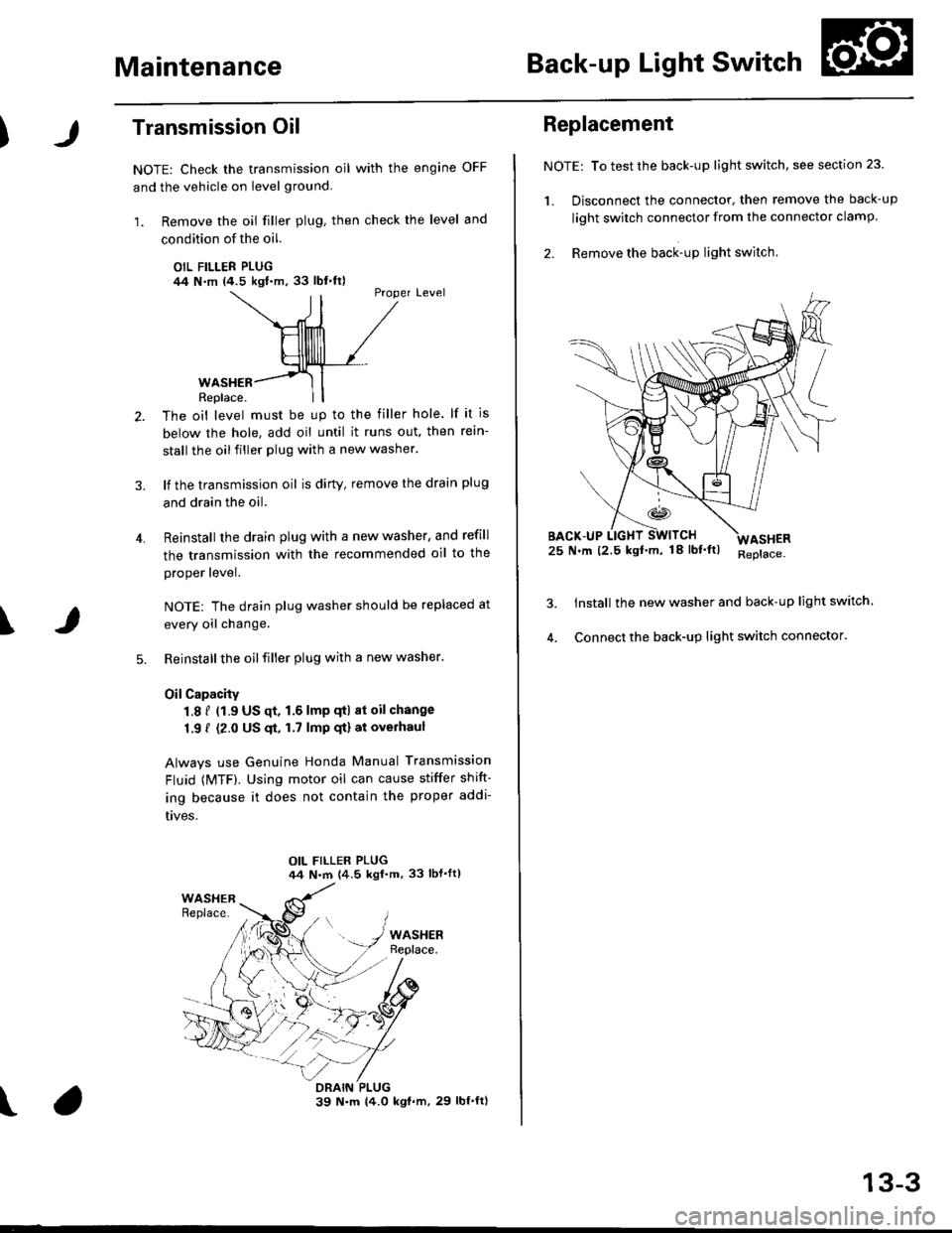
MaintenanceBack-up Light Switch
Transmission Oil
NOTE: Check the transmission oil with the engine OFF
and the vehicle on level ground.
1. Remove the oil filler plug, then check the level and
condition of the oil.
OIL FILLER PLUG/14 N.m (4.5 kgl.m,33 lbl.ft)Proper Level
4.
WASHERReplace.
The oil level must be up to the filler hole. lf it is
below the hole, add oil until it runs out. then rein-
stall the oil filler plug with a new washer.
lf the transmission oil is dirty, remove the drain plug
and drain the oil.
Reinstall the drain plug with a new washer, and refill
the transmission with the recommended oil to the
proper lever.
NOTE: The drain plug washer should be replaced at
every oil change.
Reinstall the oil filler plug with a new washer.
OilCapacity
1.8 f (1.9 US qt. 1.6 lmp qtl at oil change
1.9 { (2.0 US $, 1.7 lmp qt) at overhaul
Always use Genuine Honda Manual Transmission
Fluid {MTF). Using motor oil can cause stiffer shift-
ing because it does not contain the proper addi-
t|ves.
\
\
Replacement
NOTE: To test the back-up light switch, see section 23
1. Disconnect the connector, then remove the back-up
light swirch connector from the connector clamp.
2. Remove the back-up light switch.
25 N.m (2.5 kgf'm, 18lbf'ltl
Install the new washer and back-up light switch
Connect the back-up light switch connector.
ASHER
13-3
Page 584 of 2189
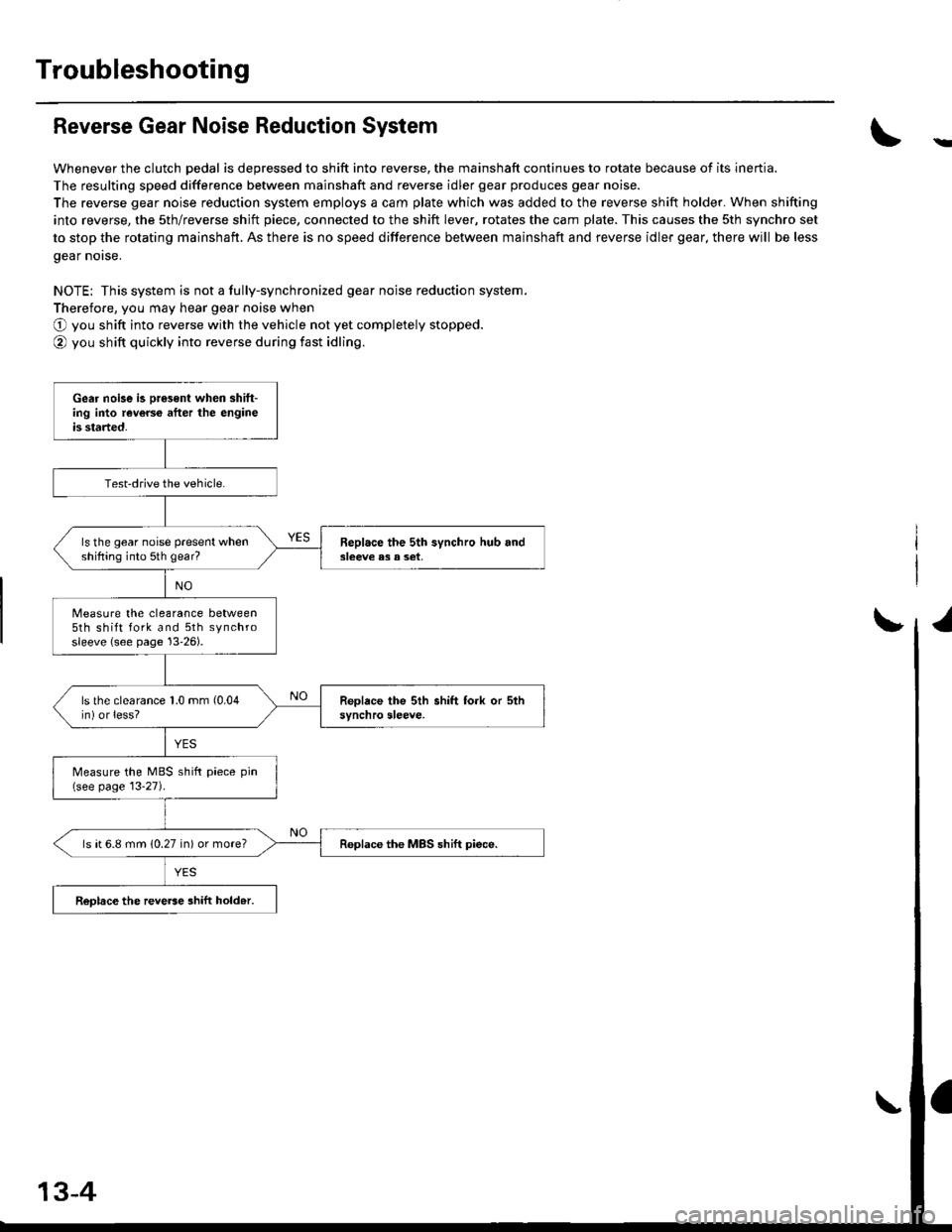
Troubleshooting
Reverse Gear Noise Reduction System
Whenever the clutch pedal is depressed to shift into reverse, the mainshaft continues to rotate because of its inertia.
The resulting speed difference between mainshaft and reverse idler gear produces gear noise.
The reverse gear noise reduction system employs a cam plate which was added to the reverse shift holder. When shifting
into reverse, the sth/reverse shjft piece, connected to the shift lever, rotates the cam plate. This causes the sth synchro set
to stop the rotating mainshaft. As there is no speed difference between mainshaft and reverse idler gear, there will be less
gear norse.
NOTE: This system is not a fully-synchronized gear noise reduction system.
Therefore, you may hear gear noise when
O you shift into reverse with the vehicle not yet completely stopped.
@ you shift quickly into reverse during fast idling.
-
Gear noise is oresent when shift-ing into reverce after the engineis started.
Test-drive the vehicle.
ls the gear noise present whenshifting into 5th gear?Beplace the 5th synchro hub and3leeve e3 a set,
Measure the clearance between5th shift fork and 5th synchrosleeve {see page 13'26).
ls the clearance 1.0 mm (0.04
in) or less?
Measure the MBS shift piece pin(see page 13-27).
ls ( 6.8 mm (0.27 in) or more?Replace the MBS shift piece.
ReDlace the reve6e ahift hold.r.
13-4