1998 HONDA CIVIC service check connector
[x] Cancel search: service check connectorPage 1767 of 2189
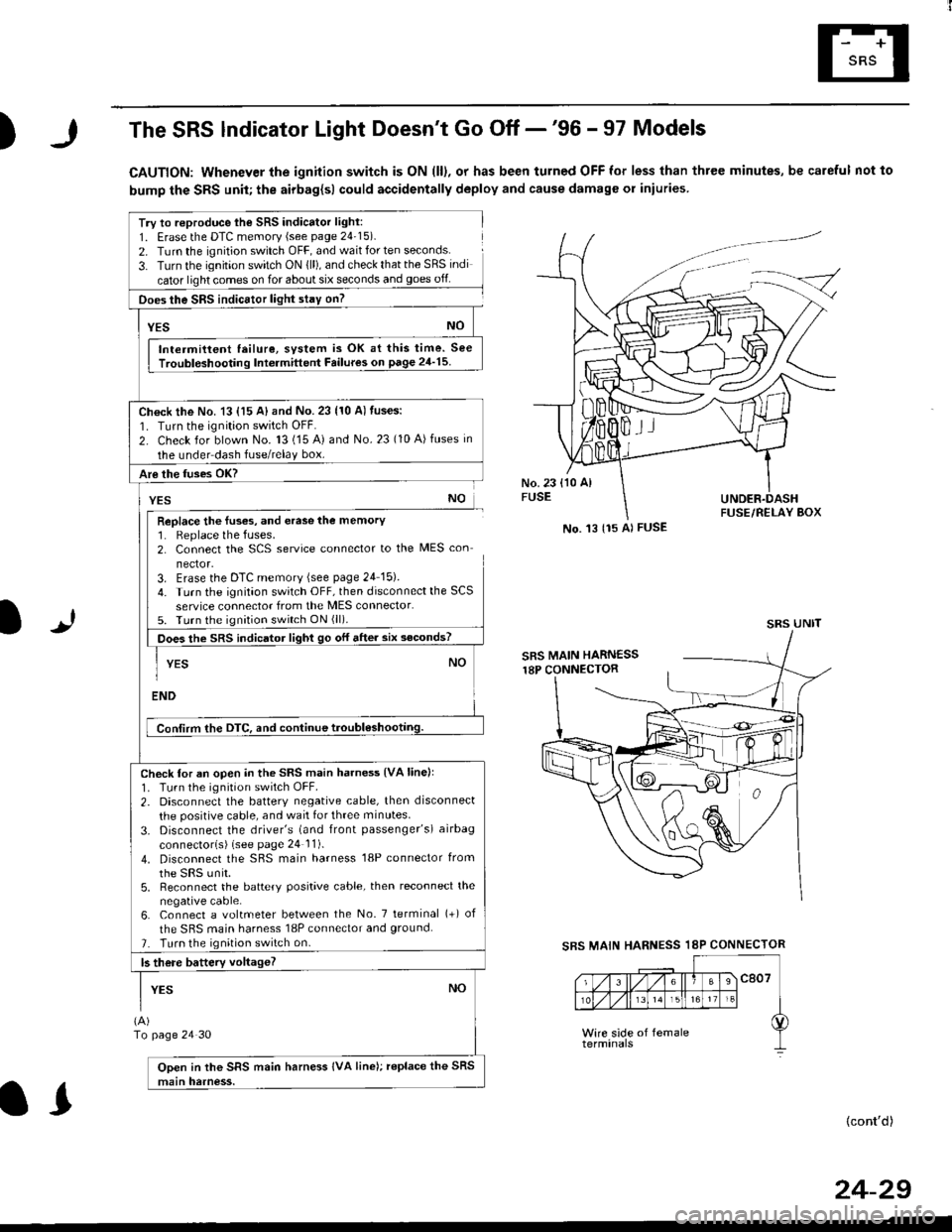
)The SRS lndicator Light Doesn't Go Off -'96 - 97 Models
CAUTION: Whenever the ignition switch is ON (ll), or has been turned OFF for less than three minutes, be careful not to
bump the SRS unit; the airbag{sl could accidentally deploy and cause damage or iniuries
Try to reproduce lhe SRS indicator light:
1. Erase the DTC memory (see page 24'15).
2. Turn the ignition switch OFF, and wait for ten seconds.
3- Turn the ignition switch ON {ll), and check that the SRS indi
cator light comes on for about six seconds and goes off
Does the SRS indicEtor light stay on?
[*NO
Intermittent lailure, system is OK at this time. See
Troubloshooting Int6rmittent Failures on page 24'15
Ch€ck the No. 13 {15 A} and No. 23 (10 A) fuses:
1. Turn the ignition switch OFF.
2. Check for blown No. 13 (15 A) and No.23 (10 A)fuses in
the under dash fuse/relay box.
Are the fuses OK?
vEs No
Replace the luses, and erase the memory1. Replace the fuses.2. Connect the SCS service connector to the MES con
nector.3. Erase the DTC memory (see page 24 15).
4. Turn the ignitaon switch OFF, then disconnect the SCS
service connector from the MES connector.5. Turn the ignition switch ON (ll).
Does the sRS indicato, tigt t go or "ne. "ii--JJl
-I YEs NO1
ENDi
Conlirm the DTC, and continue troubl6shootilg.
Check for an open in the SRS main harness {VA linell'1. Tu.n the ignition switch OFF.
2. Disconnect the battery negative cable, then disconnect
the positive cable, and wait for three minutes.
3. Disconnect the driver's (and front passenger's) airbag
connectorls) (see page 24 11).
4. Disconnect the SBS main harness '18P connector from
the sRS unir.5, Reconnect the battery positive cable, then reconnect the
negative cable.6. Connect a voltmeter between the No. 7 tetminal (+) of
the SRS main harness 18P connector and ground.
7. Turn the ignition switch on.
b there battery voltageT
YESNO
(A)
To page 24 30
Open in the SRS main harness IVA line); replace the SRS
main harness.
l.J
SBS MAIN
(cont'd)
No. 't3 {15 Al FUSE
SRS UNIT
HARNESS 18P CONNECTOR
II
24-29
Page 1784 of 2189
Troubleshooting
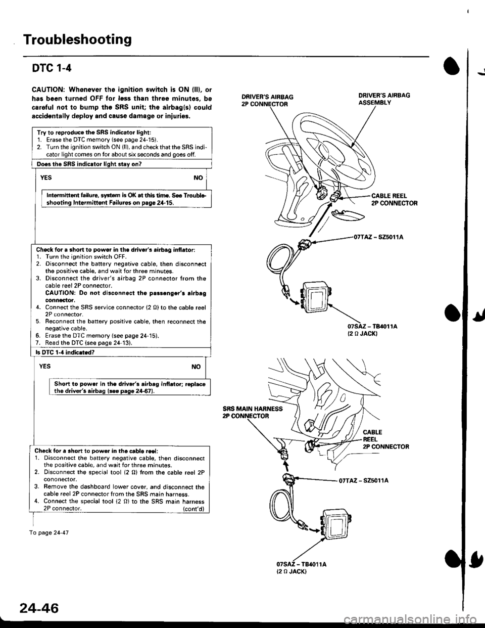
!DTC 1-4
CAUTION: Whenever ths ignition 3wiich is ON {lll, or
has boen turned OFF tor loss than three minutes, bs
caroful not to bump the SRS unit; the airbagls) could
accidoDtally deploy and cause damage or iniulies.
07SAZ - TB,()11A(2 0 JACKI
CABLEREEL2P CONNECTOR
07TAZ - Szsol'�lA
24-46
DRIVER'S AIRBAG
CABLE REEL2P CONNECTOR
Try to roproduc. the SRS indic.lor lightr1. Erase the DTC memory (see page 24-15).2. Turn the ignition switch ON (ll), and check that the SRS indi-cator light comes on tor about six seconds and goes off.
Ooes th6 SRS indicltor liqht stey on?
YESNO
Intermitid{ failure, 3y3tem b OK at this time. S€e Troublo-shooting Intormittont Failurss on pago 24.15.
Check for a 3hort to powo. in the d.iver's .irbag inflator:1. Turn the ignition switch OFF.2. Disconnect the baftery negative cable, then disconnectthe positive cable, and wait for three minut6s.3. Disconnect the driver's airbag 2P connector from thecable reel 2P connector.CAUTION: Do not disconnoct the parsengcr'r airbagconnactoa.4. Connect the SRS service connector (2 O) to the cable reel2P connector.5. Reconnect the battery positive cable, then reconnect thenegative cable.6. Erasethe DTC memory (see page 24-15).7. Read th6 DTC {seo page 24-13},
ls OTC 1-4 indic.tedT
YESNO
Short to pow.r in the driver'i rirbrg inilrtor; r€pl.cothe driver'! airbag l!e. paga 24-67).
Check for a ahort to Dow€r in tha crblo.eet:1. Disconnect the battery negative cabl€, then disconnectthe positive cable, and wait for three mrnur€s.2. Disconnect the special tool (2 O) trom the cable reel 2Pcononector.3. Bemove the dashboard lower cover, and disconnect thecable reel 2P connector trom th€ SRS main harness.4. Connect the special tool 12 0) to the SRS main harness2P connector. (cont'd)
fo page 24-47
SRS MAIN HABNESS
t2 0 JACK)
Page 1808 of 2189
Airbag
Disposal
Before scrapping any airbags (including those in a wholevehicle to be scrapped), the airbags must be deployed. lfthe vehicle is still within the warranty period, before youdeploy the airbags, the Honda District Service Managermust give approval and/or special instructions. Onlv afterthe airbags have been deployed (as the result of vehiclecollision, for example), can they be scrapped.lf the airbags appear intact (not deployed). treat themwith extreme caution.
Follow this p.ocedure:
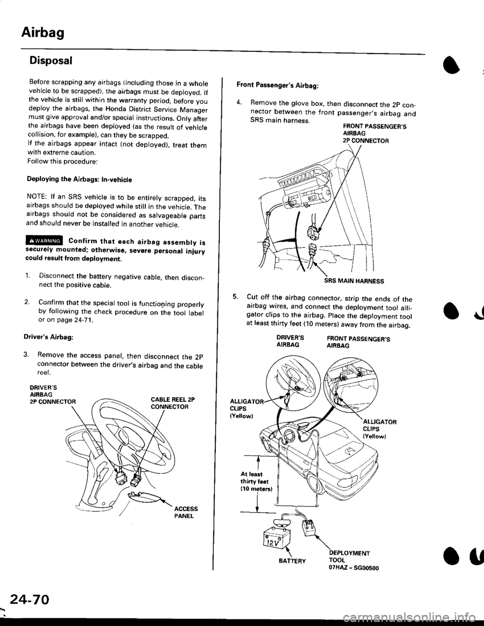
Deploying the Airbags: In.vehiclo
NOTE: lf an SRS vehicle is to be entirely scrapped, itsairbags should be deployed while still in the vehicle. Theairbags should not be considered as salvageable partsand should never be installed in another veh;cle.
!@ confirm thst oach airbag assembty issecurely mounted; otharwiso. sev€re personal iniurycould result lrom deployment.
1. Disconnect the baftery negative cable, then discon_nect the positive cable.
2. Confirm that the special tool is functioning properlyby following the check procedure on the tool labelor on page 24-'l'l .
Driver's Airbag:
3. Remove the access panel, then disconnect the 2pconnector between the driver,s airbag and the cablereet.
DRIVER'SAIRBAG2P CONNECTOR
24-70
BATTERY.U
Front Passenger's Airbag:
4. Remove the glove box, then disconnect the 2p con-nector between the lront passenger,s airbag andSRS main harness.FRONT PASSENGER'SAIREAG2P CONNECTOB
SRS MAIN HARNESS
Cut off the airbag connector, strip the ends of theairbag wires, and connect the deployment tool alli_gator clips to the airbag. place the deployment toolat least thirty feet (10 meters) away from the airbag.
a!
DRIVER'SAIRBAGFRONT PASSENGER'SAIRBAG
ALLIGACLIPS(Yellow)ALLIGATORCLIPS{Yellowl
At loastthiny toet(10 metorsl
Page 1829 of 2189
In the "OHMS" range, the DVOM will measure
resistance between two points along a circuit.
Low resistance means good continuity.
Diodes and solid-state devices in a circuit can
make a DVOM give a false reading. To check
a reading, reverse the leads, and take a
second reading. lf the readings differ, the
component is affecting lhe measurement.
Jumper Wire
Use a jumper wire to bypass an open circuit.
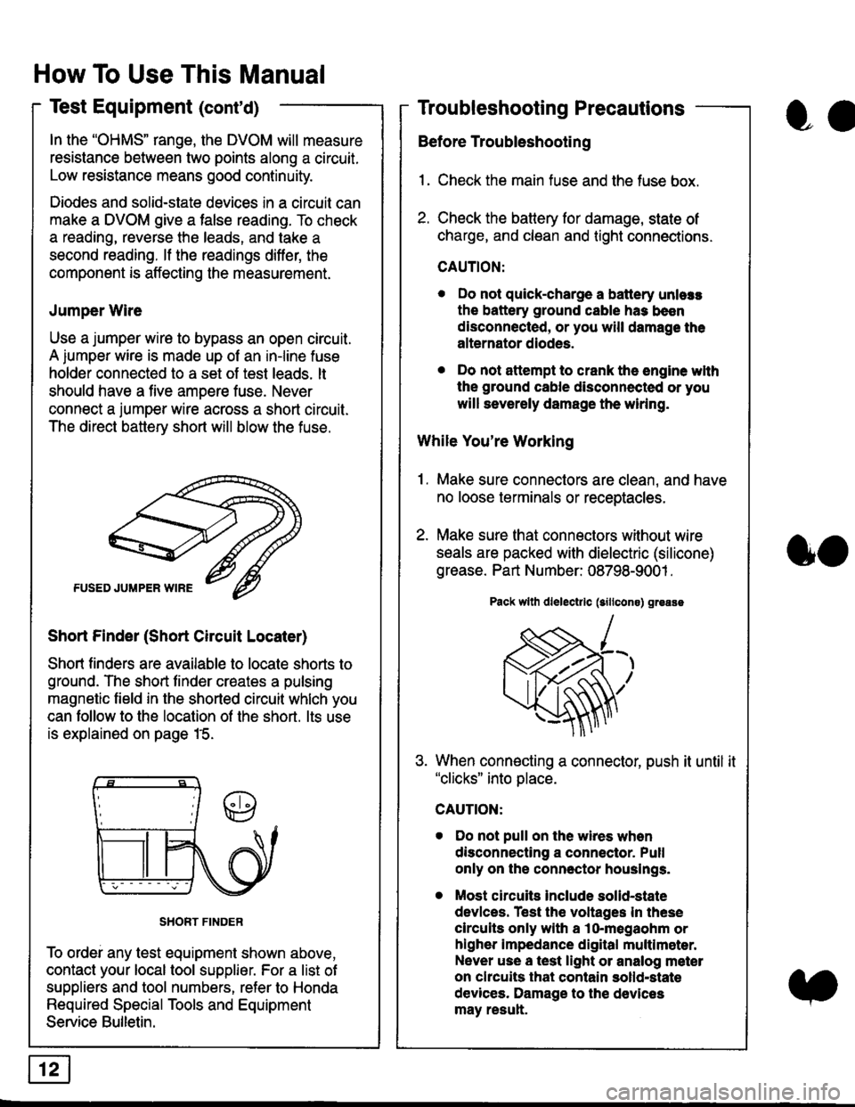
A iumper wire is made up ot an in-line fuse
holder connected to a set of test leads. lt
should have a five amoere fuse. Never
connect a jumper wire across a short circuit.
The direct battery short will blow the fuse.
Short Finder (Short Circuit Locater)
Short finders are available to locale shorts to
ground. The short tinder creates a pulsing
magnetic field in the shorted circuit whlch you
can follow to the location of the short. lts use
is explained on page 15.
SHORT FINDER
To ordei any test equipment shown above,
contact your local tool supplier. For a list of
suppliers and tool numbers, refer to Honda
Required Special Tools and Equipment
Service Bulletin.
How To Use This Manual
Test Equipment (cont'd)
oa
Troubleshooting Precautions
Before Troubleshooting
1. Check the main fuse and the fuse box.
2. Check the battery for damage, state of
charge, and clean and tight connections.
CAUTION:
. Do not quick-charge a battery unlers
the battery ground cable has been
disconnected, or you will damage the
alternator diodes.
. Do not attempt to crank the engine wlth
the ground cable disconnected or you
will severely damage the wiring.
While You're Working
1. Make sure connectors are clean, and have
no loose terminals or receptacles.
2. Make sure lhat connectors without wire
seals are packed with dielectric (silicone)
grease. Part Number: 08798-9001 .
Pack wllh dlelectrlc (sillcons) greass
When connecting a connector, push it until it"clicks" into place.
Do not pull on the wires when
disconnecting a connector. Pull
only on the connector houslngs.
Most circuits Include solid-state
devlces. Test the voltages In these
circuits only with a lo-megaohm or
higher impedance digital multlm6ter.
Never use a test light or analog meter
on chcuits that contain solld-state
devices. Damage to the devices
may result.
oo
Page 1841 of 2189
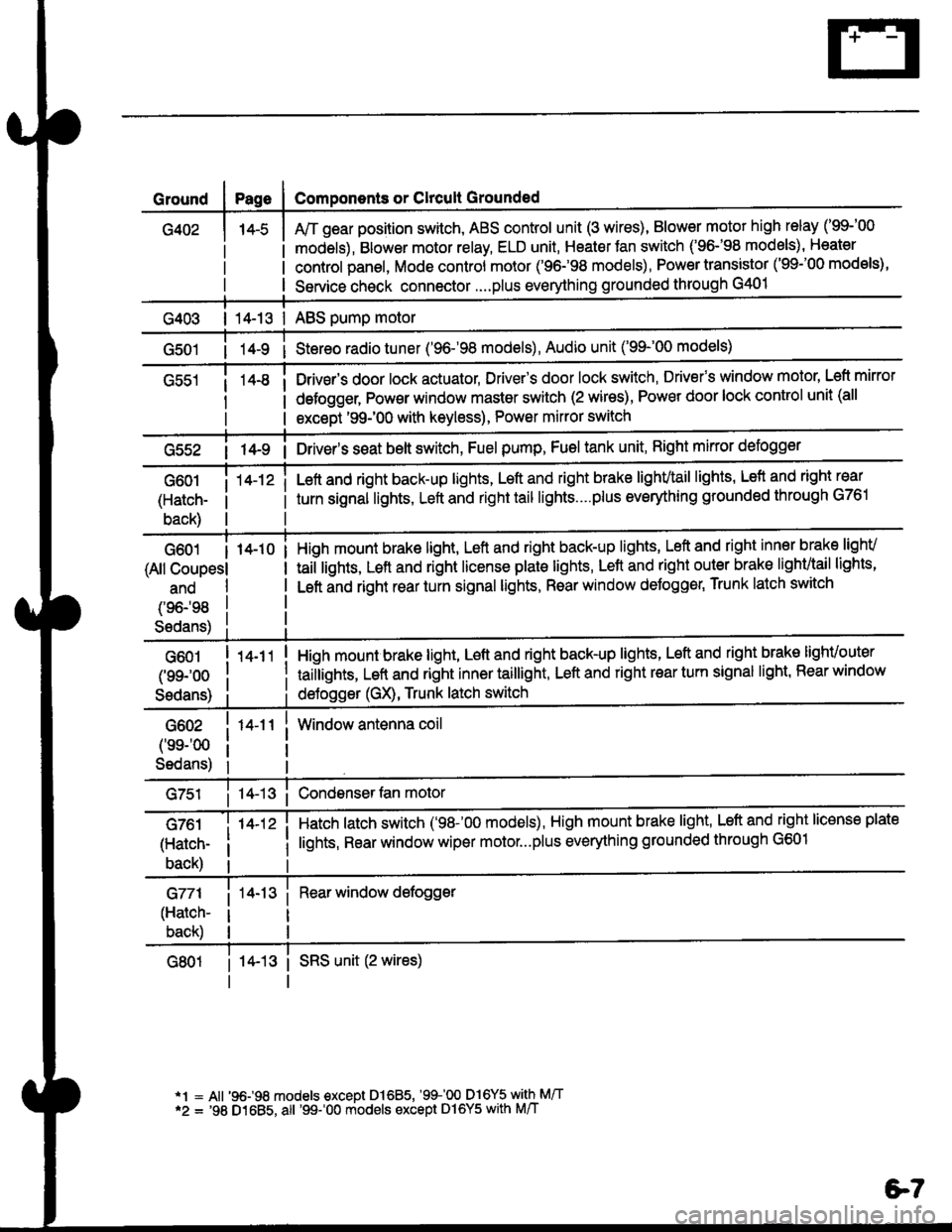
Ground
G402
Components or Clrcult Grounded
Arr gear position switch, ABS control unit (3 wires), Blower motor high relay ('99-'00
models), Blower motor relay, ELD unit, Heater Jan switch ('96-'98 models), Heater
control panel, Mode control motor ('96.�98 models), Power transistor ('99-'00 models),
Service check connector....plus everything grounded through G401
| 14-13 | ABS pump motor
1l-9 i Stereo radio tuner ('96-'98 models), Audio unit ('99-'00 models)
Drivsr's door lock actuator, Driver's door lock switch, Drivefs window motor' Left mirror
defogger, Pow€r window master switch (2 wires), Power door lock control unit (all
except '99-'00 with keyless), Power mirror switch
G55214-9 i Driver's s€at belt switch, Fuel pump, Fuel tank unit, Right mkror defogger
G601
(Hatch-
back)
14-12 iLeft and right back-up lights, Left and right brake lighvtail lights, Lefl and right rear
turn signal lights, Left and right tail lights....plus eveMhing grounded through G761
G601 I 14-10
(All Coupesl
ano
(96198
S6dans)
High mount brake light, Left and right back-up lights, Left and right inner brake lighv
taiilights, Lett and right license plale lights, Lett and right outer brak€ lighvtail lights'
Left and right rear turn signal lights, Rear window deJogger, Trunk latch switch
G601
(99-'oo
Sedans)
G602
('ss-'00
Sedans)
G761
(Hatch-
back)
G771
(Hatch-
back)
14-11
14-12 i
High mount brake light, Left and right back-up lights, Left and right brake lighvouter
taillights, Left and right inner taillight, Left and right rear turn signal light' Rear window
deJogger (GX), Trunk latch switch
Window antenna coil
Hatch latch switch ('98-'00 models), High mount brake light' Left and right license plate
lights, Rear window wiper motor...plus everything grounded through G601
Rear window defogger
14-13 i SRS unit (2 wires)
*1 = All '96-98 models €xcept Dl685, '99100 D16Y5 with M/T*2 = '98 D1685, all '99-'00 models except Dl6Y5 with M/T
e7
Page 1862 of 2189
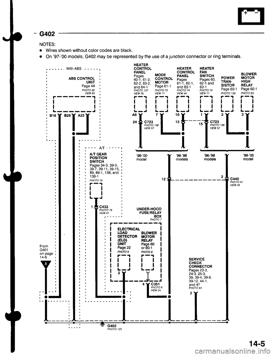
- G402
NOTES:
. Wires shown without color codes are black.
. On '97-'00 models, G402 may be represented by the use of a junction connector or ring terminals.
with ABS - - - - - I
. ABS CONTROL I' ultt '
HEATERCONTROL HEATER HEATER
iili, BB-'fi",. Eiff* 5fi::g PowER i,8;g'"'
;;; ;;; MoroR ;il--"'. ;;1-;; rRAN- H|GH
!if,6f1- ease ot-t Ino b5-.t ' fi i *- slsroR FELAY- ,pHaTa t3z pHoro 70 photoT. iioro ^ Page 60-1 Page 60-1vtEw 76 vlEW 17 V|EW 44 V|EW11 PHOTO139 PHOTO 83
r-1r-.!r-1r-1r-.|r-1
| | | | | | rl I lll
| | | | | | I ll ll IL-J L-J L-J L.J L-J L-J
Page 44PHOTO 85vtEW 63
I
I------J
I""IJ
Ifnn*"1 r'[
1"""LI'--- A/l ---_r
i , m cean; I POStflON, : swrrcH :' , Pages 34-3, 39-3, :' | 39-7,39-11,39-15,;: ' 89, 89-1, 138, and ,
; : 138-1| | PHO|OIA :' , F-'t .
'99-'00
mooel
'96-'�98
moo€ts
'9G'S
mod6ls
'99-'00
modol
a
12c440
vtEw 45
FromG401on page14-6.
v
l-
SERVICECHECKCONNECTORPages 23-3,24-3,25-3,39, 39-4, 39-8,39-12,44-1,afid 47
c402
I
I
3 cass
l;l:,12,
li
rc i UNDER-HOOD, FUSE/RELAYBOXPHAfa 7
I elecrRrca- |I LOAD BLOWER I: DETECTOR MOTOR iI (ELD) RELAY II UNlf Paoe 60 |
a W.': :;ffil iI r-r F-'r I
tt | | | |
tr | | | |I L-J L-J I
i 'r Y iL--+---J--J
I
'I&%,14.,I
14-5
Page 1871 of 2189
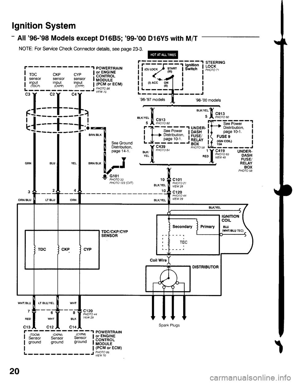
lgnition System
- All '96-'98 Models except Dl685; '99-'00 Dl6Y5 with M/T
NOTE: For Service Check Connector details, see page 23-3.
@
CKP CYPsensor sensorinput input(CKPP) (CYPP)
X,*.,
rDcsensorInpur(IDCP)
POWERTRAINor ENGINECONTROLMODULE(PCM or ECM)
POWERTRAINor ENGINECONTROLMODULE(PCM or ECM)
xr*"
BLKI/EL
I
I
BLK/YEL
I See Power
H Distribution,
J__99'�"'_
I
I
I
I
I
I
UNOER-OASHFUSE/RELAYBOX
"a*,telfi
u I """%t'3.
,rrrr.iFiFx".-,''ril'fi :T-DASH ll pagelo-1.FUSE/ I( FUSE 9
F.itl, Lq::---
".:lo63
10
BLK,YEL
10
c101
vlEW28
c'120
vlEW29
BLK
c14
c120
vlEW29
rIDcM) IGKPM) (CYPM)Sensor Sensor Sensolground ground ground
L-- - - -- -----J PHora 36
L-----------J
:L_1__I,
! iii:?ifq"l
I
**:'
*-"*,t";'
= PHO|O 33PHOTO 123ICW)
Secondary
ti <..-/4 i t
iLi:"_gl_i iL-----1!-----r
96- 97 models I 98- 00 modets
20
Spark Plugs
Page 1873 of 2189
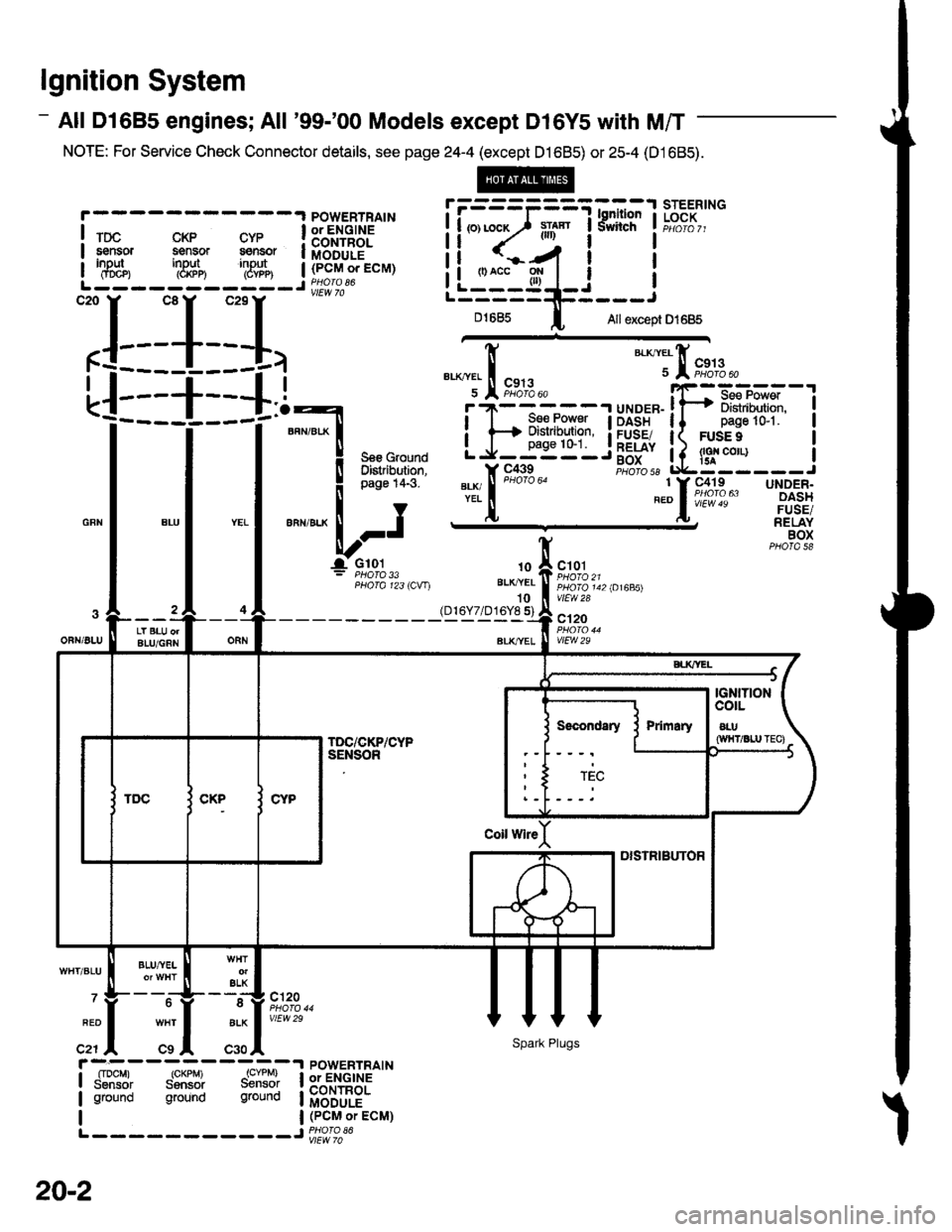
lgnition System
- All Dl685 engines; All '99-'00 Models except Dl6Y5 with M/T
NOTE: For Service Check Connector details, see page 24-4 (except D1685) or 25-4 (D1685).
STEERINGLOCKPOWERTRAIN
lm- sii.- s*- iffffiEgr
I '8f", '3#n '3#n | (Pcn' or EcM)
L------ -----J Wro 86
',L_I__J,
!l---+--l !
'i---
j----i'
fl '","?siii,xl
I I I
i*n"'."
-"1 "-l '-l *"-^lr";J
I I I ='i.{i31i",,-
All except D1685D1685
gLK.Yer t
u l9f#'
fi
"*1,[
F,*';.,
!'T-f*-'i"i! {F+ Distdbution,
LJ_gg'n'_
i.x,r
9'x*"
-.t
iF--Hs-,mT-l
ll pase lGi. I
l( FUsEe I
!Lig::___J
.I UNDER-I DASH
a FUSE/
! RELAY- BOX
1 Y C419 UNDER-^,ol',lill,l?"u' rlir?IA) RELAYBOX
.t0
BLKI/EL
10(D16Y7/D16Y8 s)
c101
PHO|O 142 lA1685)vlEw 2a
c120
vtEw 29OFN/ALULT BLU orALU/GRN
BLU,^VEL
c120
vtEw 29
ELKWHT/BLU
7
FED
c21c9
ALK
c30
;;--;;---o;;;lSensor Sonsor Sensor I
POWERTRAINor ENGINECONTROLMODULE(PCM or ECM)
ground ground gtound
L ------ -----J PHoro 36
Sec!l|dary
Sparh Plugs
20-2