Page 565 of 2189
Emission Gontrol System
Evaporative Emission (EVAP) Controls (cont'dl
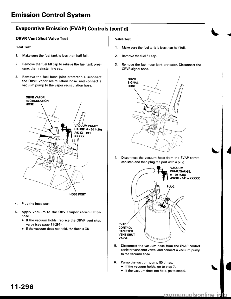
ORVR Vent Shut Valve Test
Float Test
1. Make sure the fuel tank is less than half full.
2. Remove the fuel fill cap to relieve the fuel tank pres-
sure, then reinstall the cap.
3. Remove the fuel hose joint protector. Disconnect
the ORVR vapor recirculation hose, and connect a
vacuum pump to the vapor recirculation hose.
ORVR VAPOERECIRCULATION
VACUUM PUMP/GAUGE,0 - 30 in.H9A973X - 041 -
xxxxx
Plug the hose port.
Apply vacuum to the ORVR vapor recirculation
nose.
. lf the vacuum holds, replace the ORVR vent shut
valve {see page 11-297).
. lf the vacuum does not hold, the float is OK.
4.
11-296
Vatve Tcst
1. Make sure the fueltank is lessthan halffull.
2. Remove the fuel fill cap.
3. Remove the fuel hose joint protector. Disconnect the
ORVR signal hose.
ORVRSIGNALHOSE
Disconnect the vacuum hose from the EVAP control
canister. and then plug the port with a plug.
VACUUMPUMP/GAUGE,0 - 30 in,HgA973X-041-XXXXX
CONTROLCANISTERVENT SHUTVALVE
Disconnect the vacuum hose from the EVAP control
canister vent shut valve, and connect a vacuum pump
to the vacuum hose,
Pump the vacuum pump 80 times.. lf the vacuum holds, go to step 7,. lf thevacuum does not hold, goto step9.
Page 566 of 2189
\
\
7. Connect a second vacuum pump to the OBVR signal
nose.
VACUUM PUMP/GAUGE.0 - 30 in.HgA973X - 041 -
xxxxx
Apply vacuum (1 pump) to the ORVR signal hose,
then check the vacuum on the pump in step 6.
. lf the vacuum holds, replace the ORVR vent shut
valve.
. lf the vacuum is released, the ORVR vent shut
valve is OK.
Disconnect the ORVR quick disconnect from the EVAP
canister, then plug the port on the canister.
Reapply vacuum (80 pumps).
. lf the vacuum holds, reDlace the ORVR vent shut
valve,
. lf the vacuum does not hold, inspect the EVAP can-
ister vent shut valve O-ring. lf the O-ring is OK,
replace the EVAP canister and repeat step 4.
\
I
11-297
ORVR Vent Shut Valve Replacement
1. Remove the fuel tank (see page 1 1-242).
2. Remove the ORVR vent shut valve from the fuel tank.
3. lnstall oarts in the reverse order of removal.
Page 1483 of 2189
Connector ldentification and Wire Harness Routing
D
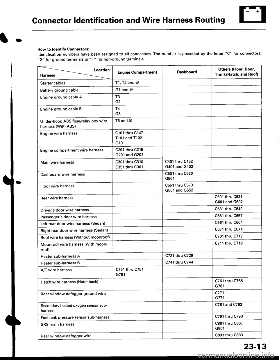
How to ldentify Connectors:
ldentification numbers have been assigned to all connectors. The number is preceded by the letter "C" for connectors,"G" for ground terminals or "T" for non-ground terminals.
Location
HarnessEngine CompartmentDashboardOthers {Floor, Door,
Trunk/Hatch, and Rootl
Starter cablesT1, T2 and @
Battery ground cableG1 and O
Engine ground cable AT3
G2
Engine ground cable BT4
Under-hood ABS fuse/relay box wire
harness (With ABS)
t5 ano (9
Engine wire harnessCl01 thru C147
T101 and T102
G101
Engine compartmenl ware harnessC201 thru C215
G201 and G202
Main wire harnessC301 thru C310
C351 thru C361
C401 thru C452
G401 and G402
Dashboard wire harnessC501 thru C520
G501
FIoor wire harnessC551 thru C573
G551 and G552
Rear wire harnessC601 thru C62l
G601 and G602
Driver's door wire harnessC631 thru C640
Passenger's door wire harnessC651 thru C657
Left rear door wire harness (Sedan)C661 thru C664
Right rear door wire harness (Sedan)C671 thru C674
Roof wire harness (Without moonroof)C701 thru C719
Moonroof wire harness {With moon-
roof)
C7l'l thru C719
Heater sub-harness AC721 thru C729
Heater sub-harness BC7 41 thtu C7 44
Ay'C wire harnessC751 thru C754
G751
Hatch wire harness (Hatchback)C761 thru C768
Rear window defogger grgund wirec771
G171
Secondary heated orygen sensor sub-
narness
C781 and C782
Fuel tank pressure sensor sub-harnessC791 thru C793
SRS main harnessC801 thru C807
G801
Rear window defogger wireC831 thru C833
Page 1510 of 2189
Gonnector ldentification and Wire Harness Routing
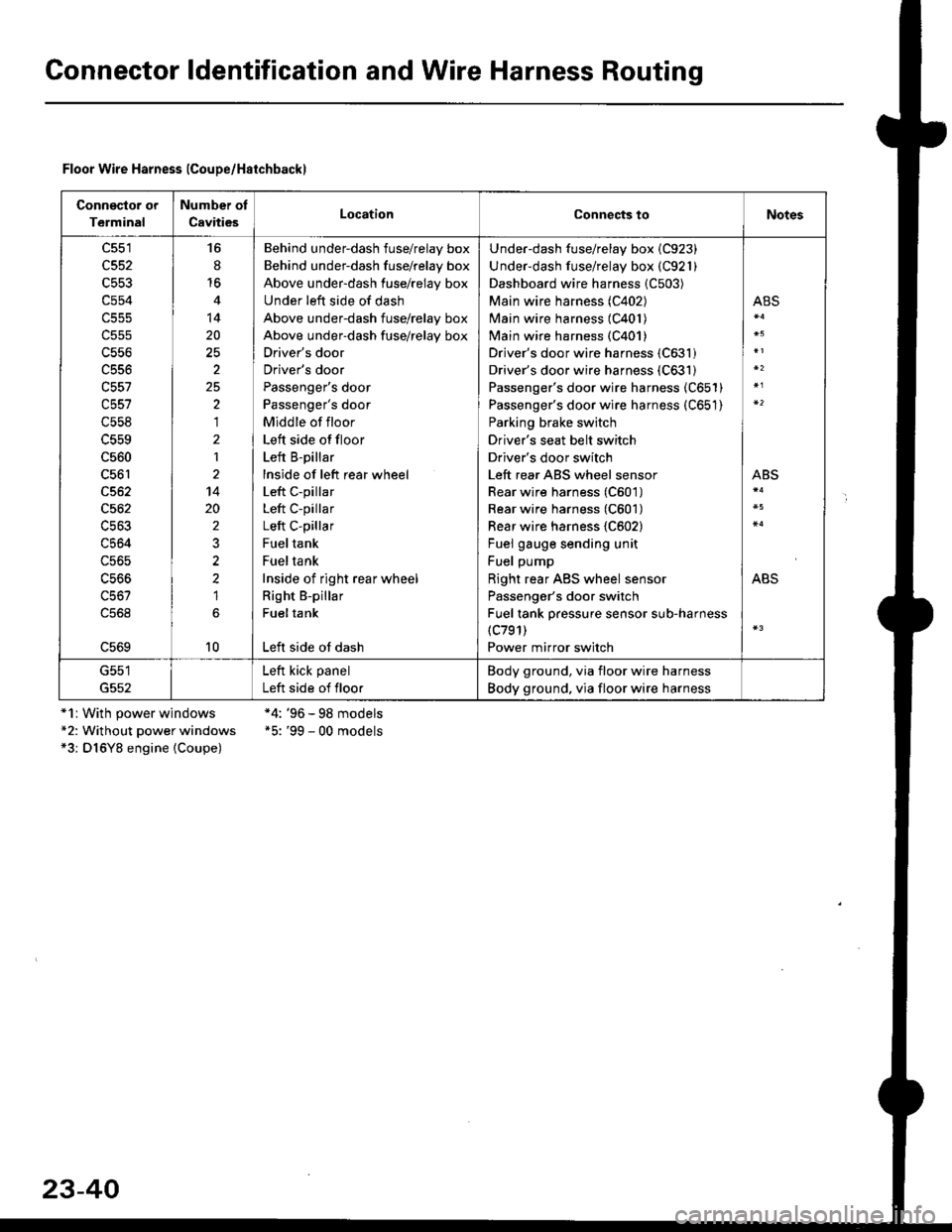
Floor Wire Harness lCoupe/Haichbackl
Connsclor or
Terminal
Number of
CavitiesLocationConnects toNotes
c551
c552
c553
c554
c556
c556
c557
c558
c560
c561
c562
c564
c56s
16
8'16
14
20
2
25,)
,I
2
1
14
20
2
2?
1
10
Behind underdash fuse/relay box
Behind under-dash fuse/relay box
Above under-dash fuse/relay box
Under left side of dash
Above under-dash fuse/relay box
Above under-dash fuse/relay box
Driver's door
Driver's door
Passenger's door
Passenger's door
Middle of floor
Left side offloor
Left B-pillar
lnside of left rear wheel
Left c-pillar
Left C-pillar
Left C-pillar
Fueltank
Fueltank
Inside of right rear wheel
Right B-pillar
Fueltank
Left side ot dash
Under-dash fuse/relay box {C923)
Under-dash fuse/relay box (C921)
Dashboard wire harness {C503)
Main wire harness (C402)
Main wire harness (C401)
Main wire harness {C401)
Driver's door wire harness (C631)
Driver's door wire harness (C631)
Passenger's door wire harness (C651)
Passenger's door wire harness (C651)
Parking brake switch
Driver's seat belt switch
Driver's door switch
Left rear ABS wheel sensor
Rear wire harness (C601)
Rear wire harness (C601)
Rear wire harness {C602}
Fuel gauge sending unit
Fuel pump
Right rear ABS wheel sensor
Passenger's door switch
Fuel tank pressure sensor sub-harness(c791)
Power mirror switch
ABS
ABS
ABS
G551
G552
Left kick panel
Left side of floor
Body ground, via floor wire harness
Body ground. via floor wire harness
*1r With power windows*2: Without power windows*3: D16Y8 engine {Coupe)
*4: '96 - 98 models*5: '99 - 00 models
23-40
Page 1512 of 2189
Gonnector ldentification and Wire Harness Routing
Connector ol
Terminal
Number of
CavitiesLocationConnects toNotes
c553
c554
c556
c557
c557
c558
c559
c560
c561
c562
c563
c564
c565
c566
c567
L5bY
c570
c511
c572
c513
6
14
25
2
25
'|
1
2't4
1'10
6
6
I
1
Behind underdash fuse/relay box
Behind under-dash fuse/relay box
Above under-dash fuse/relay box
Under left side of dash
Above under-dash fuse/relay box
Drlver's door
Driver's door
Passenger's door
Passenger's door
Middle of floor
Left side of floor
Right B-pillar
lnside of left rear wheel
Left C-pillar
Left C-pillar
Fuel tank
Fuel tank
Inside of right rear wheel
Left B-pillar
Left side of steering wheel
Right B-pillar
Left B-pillar
Left quarter panel
Right quarter panel
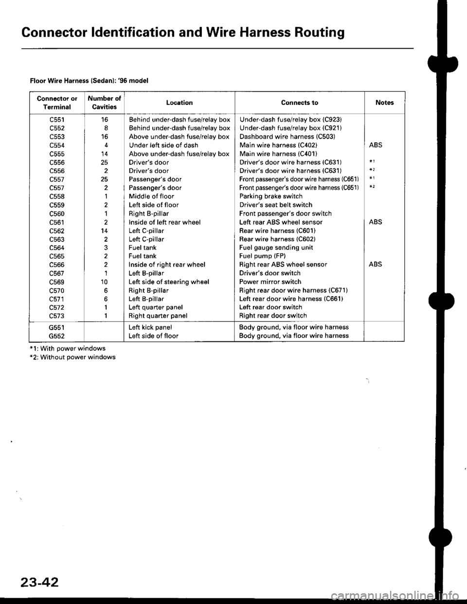
Under-dash fuse/relay box {C923)
Under-dash fuse/relay box (C921)
Dashboard wire harness (C503)
Main wire harness (C402)
Main wire harness (C401)
Driver's door wire harness (C631)
Driver's door wire harness (C631)
Front passenger's doorwire harness (C651)
Front passenge/s doorwire harness (C651)
Parking brake switch
Driver's seat belt switch
Front passenger's door switch
Left rear ABS wheel sensor
Rear wire harness (C601)
Rear wire harness (C602)
Fuel gauge sending unit
Fuel pump {FP)
Right rear ABS wheel sensor
Driver's door switch
Power mirror switch
Right rear door wire harness (C671)
Left rear door wire harness (C661)
Left rear door switch
Right rear door switch
ABS
ABS
ABS
G552
Left kick panel
Left side of floor
Body ground, via floor wire harness
Body ground, via floor wire harness
Floor Wire Harness lSedanl: '96 model
*l:With power windows*2; Without power windows
23-42
Page 1514 of 2189
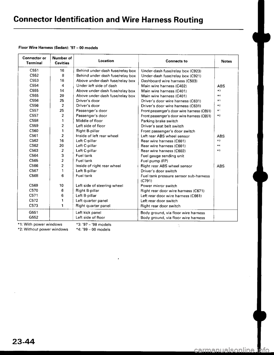
Gonnector ldentification and Wire Harness Routing
Floor Wire Harness (Sedanl: '97 - 00 models
Connector or
Terminal
Number of
CavitiesLocationConnects toNotes
c552
c553
c554
c555
c556
c557
c557
c558
c559
c560
c56'l
c562
c563
c564
c566
c568
c569
c570
c571
c572
16
8
14
20
25
2
2
1
2
1
20
2
2
2
1
l0
1
1
Behind under-dash fuse/relay box
Behind under dash fuse/relay box
Above under-dash fuse/relay box
Under left side of dash
Above under-dash fuse/relay box
Above under-dash fuse/relay box
Driver's door
Driver's door
Passenger's door
Passenger's door
Middle of floor
Left side of floor
Right B-pillar
Inside of left rear wheel
Left C-pillar
Left C-pillar
Left C-pillar
Fuel tank
Fuel tank
Inside of righr rear wheel
Left B-pillar
Fuel tank
Left side of steering wheel
Righr B,pillar
Left B pillar
I ofr ^,,.riar ^.^al
Right quarter panel
Under-dash fuse/relay box (C923)
Under-dash fuse/relay box (C921)
Dashboard wire harness (C503)
Main wire harness (C402)
Main wire harness (C401)
Main wire harness (C401)
Driver's door wire harness (C631)
Driver's door wire harness {C631}
Front passenger's door wire harness (C651)
Front passenger's door wire harness (C651)
Parking brake switch
Driver's seat belt switch
Front passenger's door switch
Left rear ABS wheel sensor
Rear wire harness (C601)
Rear wire harness (C601)
Rear wire harness (C602)
Fuel gauge sending unit
Fuel pump (FP)
Right rear ABS wheel sensor
Driver's door switch
Fuel tank pressure sensor sub-harness(c791)
Power mirror switch
Right rear door wire harness (C671)
Left rear door wire harness (C661)
Left rear door switch
Right rear door switch
ABS
ABS
ABS
G551Left kick panel
Left side of floor
Body ground, via floor wire harness
Body ground, via floor wire harness
"1r With power windows*2: Without power windows
*3:'97 - '98 models*4: '99 - 00 models
23-44
Page 1530 of 2189
Connector ldentification and Wire Harness Routing
Rear Heatod Oxygen Sensor Sub-harness
Connector or
Terminal
Number of
CavhiesLocationConnects toNotes
c7a1
c782
Under middle of dash
Under middle of dash
Main wire harness (C432)
Secondary heated oxygen sensor(Secondarv HO2S)
Fuel Tank Pressure Sensor Sub-harness
Connector or
Terminal
Number of
CavitiesLocationCono€cts toNotes
c791
c192
c793
6Middle of floor
Left side of fuel tank
Left side of fuel tank
Floor wire harness (C568: Coupe/
Hatchback, C574; Sedan)
Fuel tank pressure sensor
EVAP two way valve
FUEL TANK PRESSURE SENSOR
23-60
Page 1613 of 2189
J
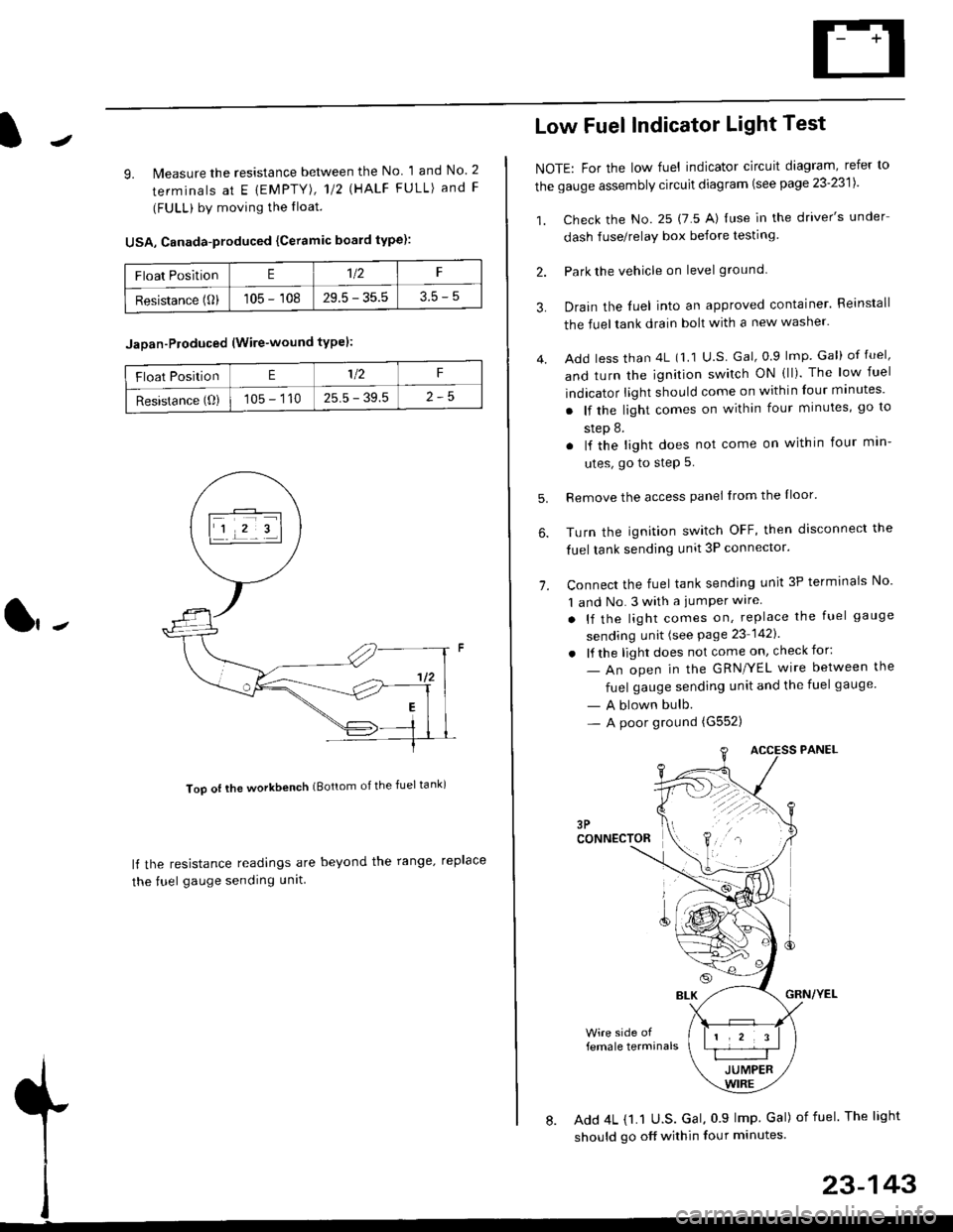
9. lMeasure the resistance between the No 1 and No. 2
terminals at E {EMPTY), 112 \HALF FULL) and F
(FULL) by moving the lloat.
USA, Canada-produced {Ceramic board type):
Too ot lhe workbench (Bottom of the fuel tank)
ll the resistance readings are beyond the range. replace
the fuel gauge sending unit
Float PositionE1t2F
Resistance (0)105 - 10829.5 - 35.53.5-5
Jaoan-Ploduced (Wire-wound typel:
Float PositionE1/2F
Resistance (O)105 - 11025.5 - 39.5
Low Fuel Indicator Light Test
NOTE: For the low fuel indicator circuit diagram, refer to
the gauge assembly circuit diagram (see page 23'2311.
1. Check the No. 25 (7 5 A) luse in the driver's under
dash fuse/relay box before testing
2. Park the vehicle on level ground.
3.
4.
Drain the luel into an approved container. Reinstall
the fueltank drain bolt with a new washer.
Add less than 4L (1 1 U.S Gal, 0.9 lmp Gal) of fuel,
and turn the ignition switch ON (ll). The low fuel
indicator light should come on within four minutes'
. lf the light comes on within four minutes, go to
step 8.
. lf the light does not come on within four min-
utes, go to step 5.
Remove the access panel lrom the Iloor'
Turn the ignition switch OFF, then disconnect the
fuel tank sending unit 3P connector.
Connect the fuel tank sending unit 3P terminals No'
1 and No. 3 with a jumPer wire
. lf the light comes on, replace the fuel gauge
sending unit (see Page 23 1421
. lf the light does not come on, check for:
- An open in the GRN/YEL wire between the
fuel gauge sending unit and the fuel gauge
- A blown bulb.- A poor ground (G552)
6.
1.
female terminals
8. Add 4L {1.1 U.S. Gal, 0 9 lmp Gal) of fuel The light
should go off within four minutes.
23-143