1998 HONDA CIVIC egr valve
[x] Cancel search: egr valvePage 1028 of 2189
Transmission
Gooler Flushing
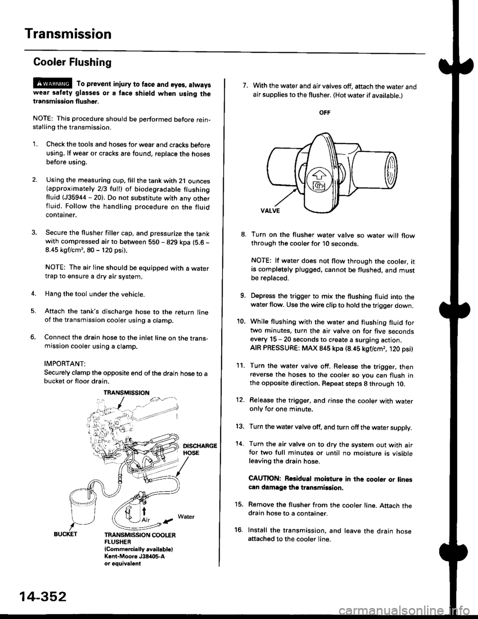
@ To prevent iniury to face and eyes, alwayswear safety glasses or a tace shield when using thetransmission flusher.
NOTE: This procedure should be performed before rein-stalling the transmission.
'1. Check the tools and hoses for wear and cracks before
using. lf wear or cracks are found, reDlace the hoses
before using.
4.
Using the measuring cup. fill the tank with 2,1 ounces(approximately 2/3 full) of biodegradable flushingfluid (J35944 - 20). Do not substitute with any otherfluid. Follow the handling procedure on the fluidcontatner.
Secure the flusher filler cap, and pressurize the tankwith compressed air to between 5S0 - 829 kpa (5.6 -
8.45 kgf/cm'�, 80 - 120 psi).
NOTE: The air line should be equipped with a watertrap to ensure a dry air system,
Hang the tool under the vehicle.
Attach the tank's discharge hose to the return lineoi the transmission cooler using a clamp.
Connect the drain hose to the inlet line on the trans-mission cooler using a clamp.
IMPORTANT:
Securely clamp the opposite end ofthe drain hose to abucket or floor drain,
t
TRANSMISSION COOLERFLUSHER{Commercially available)Kent-Moore J384O5-Aor oouivalent
TRANSMISSION
14-352
7. With the water and air valves off, attach the water andair supplies to the flusher. (Hot water if available.)
8. Turn on the flusher water valve so water will flowthrough the cooler for 10 seconds.
NOTE: lf water does not flow through the cooler, itis completely plugged, cannot be flushed, and mustbe replsced.
9. Depress the trigger to mix the flushing fluid into thewater flow. Use the wire clip to hold the trigger down.
'10. While flushing with the water and flushing fluid fortwo minutes. turn the air valve on for five secondsevery 15 - 20 seconds to create a surging action.AIR PRESSURE: MAX 845 kpa (8.45 kgflcmr, 120 psi)
11. Turn the water valve off. Release the trigger, thenreverse the hoses to the cooler so you can flush inthe opposite direction. Repeat steps 8 through 10.
12. Release the trigger. and rinse the cooler with wateronly for one minute.
13, Turn the water valve off, and turn off the water supply.
'14. Turn the air valve on to dry the system out with airfor two full minutes or until no moisture is visibleleaving the drain hose.
CAUTION: Rosidual mobturo in the qooler or linescln damage the transmission,
15. Remove the flusher from the cooler line. Attach thedrain hose to a container.
16. Install the transmission. and leave the drain hoseattached to the cooler line.
Page 1073 of 2189
)
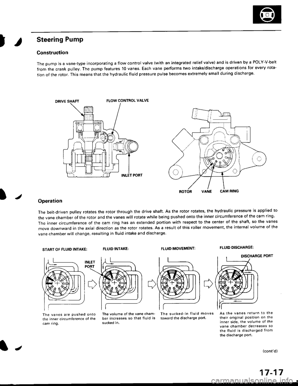
Steering Pump
Construction
The pump is a vane-type incorporating a flow control valve (with an integrated relief valve) and is driven by a POLY-V-belt
from the crank pulley. The pump features 10 vanes. Each vane performs two intake/discharge operations for every rota-
tion of the rotor. This means that the hydraulic fluid pressure pulse becomes extremely small during discharge.
/
ROTORVANE CAM RING
Operation
The belt-driven pulley rotates the rotor through the drive shaft. As the rotor rotates, the hydraulic pressure is applied to
the vane chamber of rhe rotor and the vanes will rotate while being pushed onto the inner circumference of the cam ring.
The inner circumference of the cam ring has an extended portion with respect to the center of the shaft, so the vanes
move downward in the axial direction as the rotor rotates. As a result of this roller movement. the internal volume of the
vane chamber will change, resulting in fluid intake and discharge
START OF FLUID INTAKE:FLUID INTAKE:FLUID MOVEMENT:FLUID DISCHARGE:
The vanes are pushed ontothe inner circumference ol the
cam ring,
lhe volume ofthe vane cham- The sucked-in fluid moves
ber increases so that fluid is toward the discharge port.
sucked in.
As the vanes return to the
their original Position on theinner side, the volume of the
vane chamber decreases so
the fluid is discharged from
the discharge port.
(cont'd)
a-t 4-I I- | t
FLOW CONTROL VALVE
J
Page 1486 of 2189

Connector ldentification and Wire Harness Routing
Engine Wire Harness lD16Y5, D16Y8 enginss): '96 - 98 models
Connector or
Torminal
Numbsr of
CavitissLocationConnects toNot€s
c 101c102c103c104c104c105c106c107c108c 109c110c111c112c113c114c115c116cl17c118c119c120cl21
c122c123cl23c124
c125
c127c12Ac129c130c131c132c 133c134c135
c136
c138c139c140c 141c142c 143c144cl44c145c'146cl47
10
1
22
14l4322l0I
2
2
2
2120
3l
14
14
1222
2
2
22
Left side of engine compartmentMiddle of engineMiddle of engineLeft side of engine companmentLeft side of engine compartmentMiddle of engineMiddle of engineMiddle of engineMiddle of engineMiddle of enginefvliddle of engineMiddle of engineMiddle of engineMiddle of engineMiddle of engineMiddle of engineMiddle of engineLeft side of engine compartmentMiddle of engineMiddle of engineMiddle of engineMiddle of engine
Middle of engineMiddle of engineMiddle of engineMiddle of engineMiddle of engineMiddle of engineMiddle of engineMiddle of engineMiddle of engineRight side of engine companmentBehind right kick panelUnder right side of dashUnder riOht side of dashUnder right side of dashUnder right side of dashUnder right side of dashUnder right side of dash
Under right side of dash
Under right side of dash
Middle of engineMiddle ot enginel iddle of engineMiddle of engineMiddle of ongineMiddle of engineLeft side of engine compartmentMiddle of engineMiddle of engineRight side of engine compartmentRight side of engine compartmentRight side of engine compartment
USACanada
Afi
USA
-' (A/r)
Main wire harness (C303)Crankshaft speed fluctuation (CKF) sensorEngine oil pressure switchAlternatorAlternatorNo. 'l fuel injectorNo. 2 fuel injectorNo.3 fuel injectorNo. 4 fuel injectorIAC valveThrottle position (TP) sensorl\4anifold absolute pressure (MAP) sensorIntake air temperature (lAT) sensorPower steering pressure {PSPI switchEVAP purge control solenoid valveJunction connectorJunction conn€ctorVehicle speed sensor {VSS}Countershaft speed sensorEngine coolant temp€rature (ECT) switch ADistributorEngine coolant temperature (ECT) sendingunrtEngine coolant temperature (ECT) sensorPrimary HO2S (sensor'l)Primary HO2S (sensor 1)Back-up light switchLock-up control solenoid valveSecondary HO2S (sensor 2)Mainshaft speed sensorLinear solgnoid valveShift control solsnoid valveStarter solenoidJunction connectorMain wire harnesE (C446)ECM/PCMPCMECMiPCMECM/PCMMain wire harness (C305)
Main wire harness (C305)
Main wire harness (C305)
Knock sensor (KS)IAC valveVTEC solenoid valveVTEC pressure switchEVAP control canister vent shut valveEGR control solenoid valveSecondary gear shaft speed sensorEGR valveEGR valveDrive pulley speed sensorSolenoid connector {CVT)Driven pulley speed sensor
*, (M/T)M/T*" INT\
*, tAtf)
NT:'96 model*,(A,/T):'97 - 98mooets
moqets
M/T
-1 (l,/T)*, (A,/T)-,(4,/T)*1 {M/T)*, (A,/T)*1 (CW)*, (A,T)
T101r102Left side of engine companmentRight side of engine companmentAlternatorUnder-hood fuse/relay boxG 101Middle of engineEngine ground, via engine wire harness
2
*1: Dl6Y5 engine*2: D16Y8 engine*3: D16Y5 (Ay'T), D16Y8 engines
3-16
Page 1488 of 2189
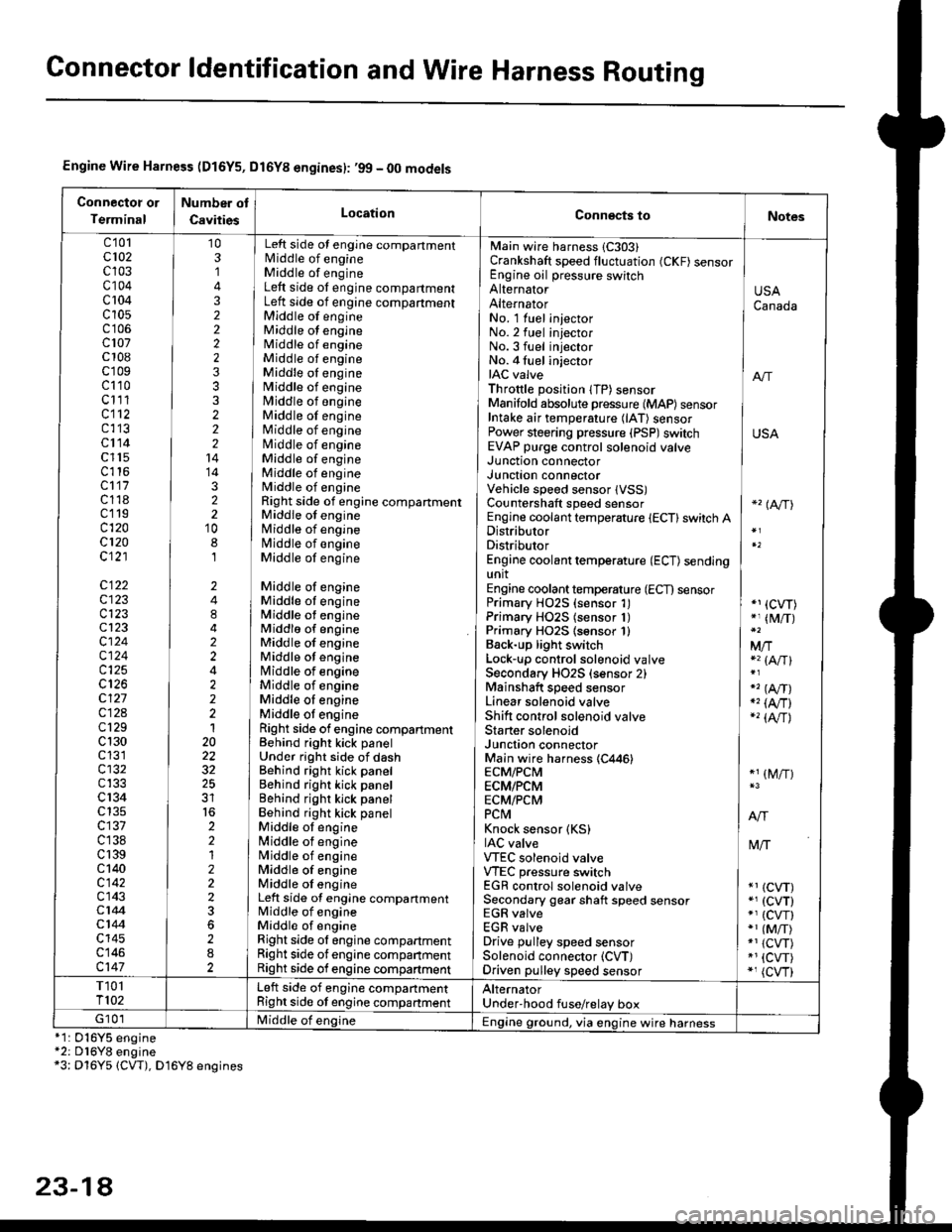
Gonnector ldentification and Wire Harness Routing
Engine Wire Harness (D16Y5, Dl6Yg engines): ,99 - 00 models
Connectot or
Terminal
Number ot
CavitiesLocationConn€cts toNotes
c'101cl02c103c104c 104c10s
c107c 108c'r09c110c111cl12c113cl14c l15c116cl17c118c119c120cl20c121
c122c123c123cl23cl24c124c125
c127c12Ac129c 130c131cl32c133c 134c135c137c138c 139c 140c142c143c144cl44c145c146c147
103,]
322223332221414322'10
8,l
2484224222120
32
2212223
282
No. 1 luel injector INo.2 fuel injectorNo.3 fuel injector ]No. 4 fuel injector iIAC valve I anThrottle position lTP) sensorManifold absolute pressure {MAP) sensor IIntake air temperature (lAT) sensor IPower steering pressure (PSP)switch USAEVAP purge control solenoid valve ]
Main wire harness 1C303)Crankshaft speed fluctuation (CKF) sensorEngine oil pressure switchAlternatorAlternator
Left side ot engine compartmentlvliddle of engineMiddle of engineLeft side ot engine compartmentLeft side of engine compartmentMiddle of engineMiddle ot engineMiddle of engineMiddle of engineMiddle oI engineMiddle of engineMiddle of engineMiddle of engineMiddle of engineNliddle of engineMiddle of engineMiddle of engineMiddle of engineRight side of engine compartmentMiddle of engineMiddle of engineN4iddle of engineMiddle of engine
Middle of engineMiddle ot engineMiddle ot engineMiddlo of engineMiddle of engineMiddle ot enginelrliddle of engineMiddle of engineMiddle oI engineMiddle ot engineRight side of engine compartmenlBehind right kick panelUnder right side of dashBehind right kick panelBehind right kick panelBehind righr kick panelBehind right kick panelMiddle ot engine[,liddle of engineN4iddle of engineMiddle of engineMiddle oI engineLeft side of engine compartmentMiddle of engineMiddle of engineRight side ol engine compartmentRight side of engine companmentRight side of engine compartment
USACanada
Junction connectorJUnct|On COnnectorVehicle speed sensor lVSS)Countershaft speed sensorEngine coolant temperature {ECT} switch ADistributorDistributorEngine coolant temperature (ECT) sendingunitEngine coolant temperature (ECT) sensorPrimary H02S (sensor 1)Primary HO2S (sensor 1)Primary HO2S lsensor 1)Back-up light switchLock'!p control solenoid valveSecondary HO2S (sensor 2)Mainshaft speed sensorLinear solenoid valveShift control solenoid valveStarter solenoidJunction connectorMain wire harness (C446)ECM/PCMECM/PCMECM/PCMPCtvtKnock sensor (KS)IAC valveVTEC solenoid valveVTEC pressure switchEGR control solenoid valveSecondary gear shaft speed sensorEGR valveEGR valveDrive pulley speed sensorSolenoid connector (CVT)Driven pulley speed sensor
*'� (A/TI
*1 (CVT)*, (M/T)
Mfia (A/Tl
" (A,/T)., (4,/r)-'� {AlrJ
*1 (M/T)
tvliT
*1 (CVT)*, (cvT)*' (cw)*1 (MiT)*1 {CVT)*1 {CVT)*, (cvr)
T101T102Left side of engine companmentRight side ot engine companmentAlternatorUnder'hood fuse/relay boxG 101Middle of englne IEngine ground, via engine wire harness*1: 016Y5*2: D16Y8*3: Dl6Y5
engineengine(CW), D16Y8 engines
23-14
Page 1535 of 2189
lr-
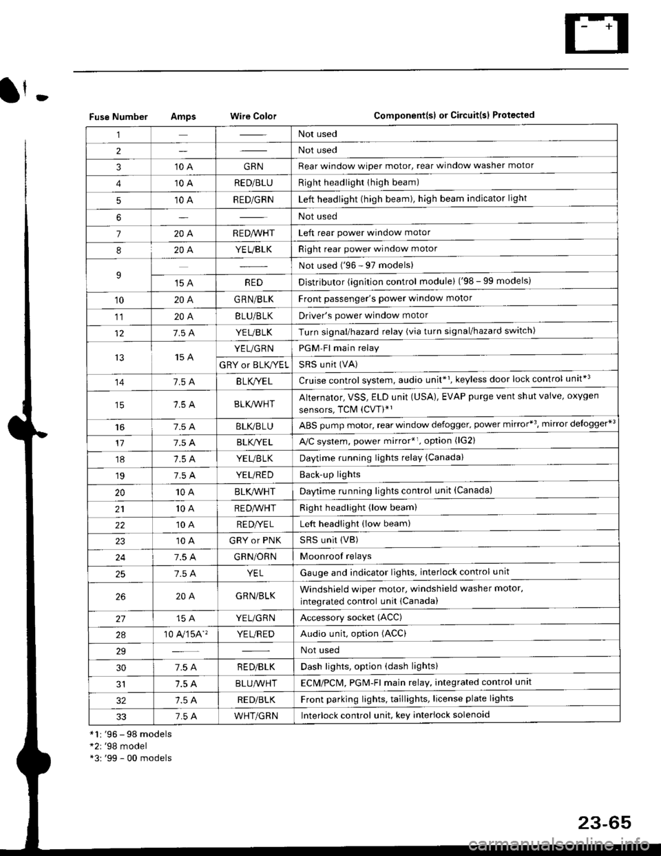
Fuse NumberAmpswire ColorComponent{sl or Circuit(sl Protected
*1r '96 - 98 models*2r '98 model*3: '99 - 00 models
,lNot used
2Not used
310 AGRNRear window wioer motor, rear window washer motor
410 ARED/BLURight headlighr thigh beam)
510 ARED/GRNLeft headlight (high beam), high beam indicator light
6Not used
7204R E D/VVHTLeft rear power window motor
820A.YEUBLKRight rear power window motor
9Not used ('96 - 97 models)
't5 AREDDistributor (ignition control module) ('98 - 99 models)
10204G RN/BLKFront passenger's power window motor
1120ABLU/BLKDriver's power window motor
127.5 AYEUBLKTurn signal/hazard relay (via turn signal/hazard switch)
t515 AYEL/GRNPGM-Fl main relay
GRY or BLK,^/ELSRS u nit (VA)
141.54B LK/YE LCruise control system, audio unit*1, keyless door lock control unit*3
BLK/lr'r'HTAlternator, VSS, ELD unit (USA), EVAP purge vent shut valve, oxygen
sensors, TCM (CVT)*'
t6BLI(,/BLUABS pump motor, rear window defogger. power mirror*3, mirror delogger*3
177.5 ABLK,/YE LA,/C system, power mirror*r. option (lG2)
18YEUBTKDaytime running lights relay (Canada)
197.5 AYEUREDBack'up lights
2010ABLK/VVHTDaytime running lights control unit (Canada)
2110 AREDA/VHTRight headlight (low beam)
2210 ARE DI/E LLeft headlight (low beam)
10 AGRY or PNKSRS UNit (VB)
247.5 AGRN/ORNMoonroof relays
257.5 AYELGauge and indicator lights. interlock control unit
204GRN/BLKWindshield wiper motor, windshield washer motor,
integrated control unit {Canada)
15 AYEL/GRNAccessory socket (ACC)
2a10 A,/'�]5A''YE L/R EDAudio unit, option (ACC)
29Not used
307.5 AR ED/BLKDash lights, option (dash lights)
1.5 ABLUA/VHTECM/PCl\4, PGM-Fl majn relay, integrated control unit
RED/BLKFront parking lights, taillights, license plate lights
337.5 AWHT/GRNlnterlock control unit. key interlock solenoid
23-65
Page 1540 of 2189
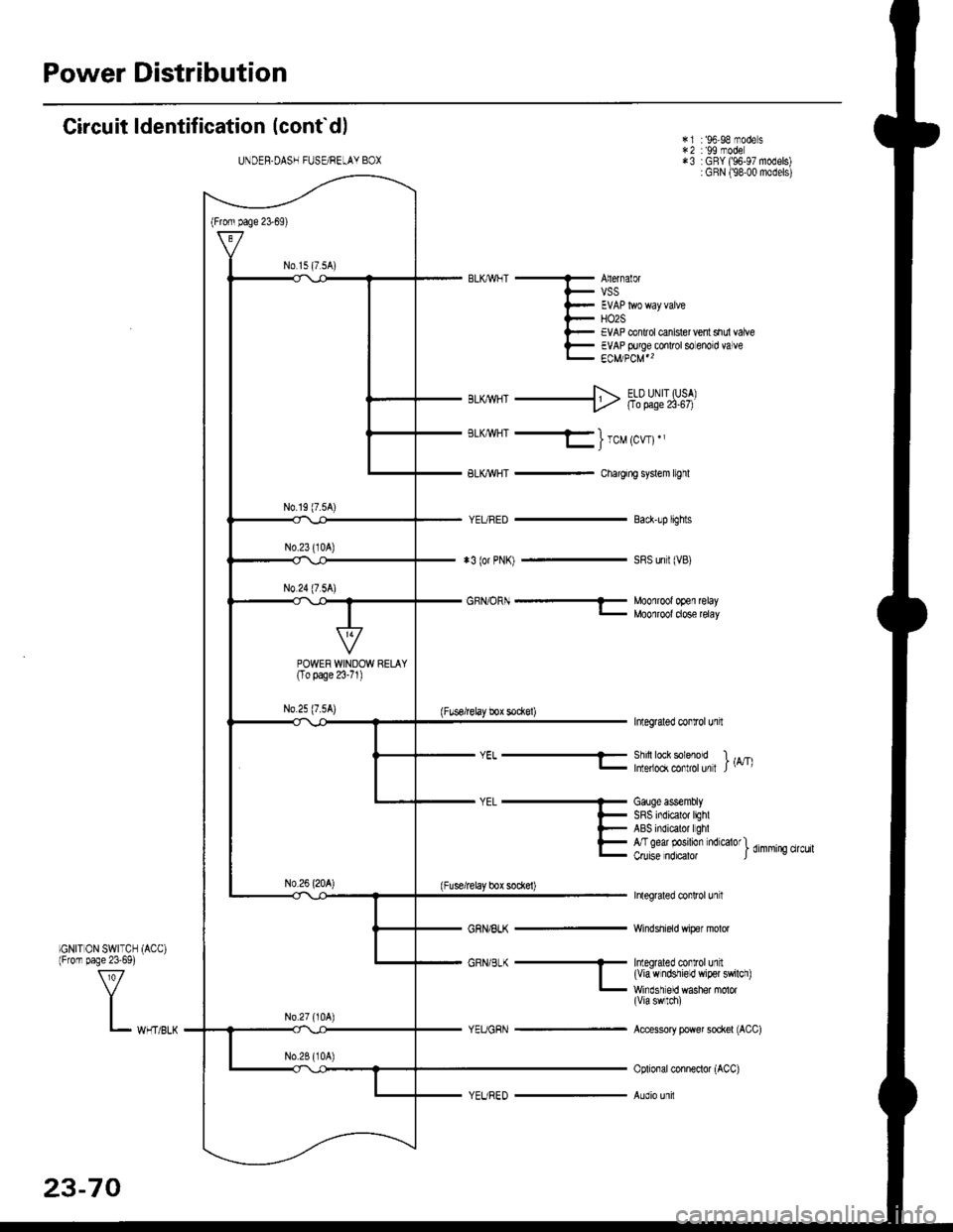
Power Distribution
Circuit ldentification (cont'd)
IGN|T 0N SWTTCH (ACo)lFrom page 23-69)
*3 (or PNn -
Anernal0rVSS
HO2SEVAP conlrol canister vent shr,,l vafoeEVAP Flrge conrol so enord valveECM/PCM"
Back-!p lighls
SRS unri (VB)
i.1 :'96,98 modesr.2 : 99 mode*3 :GRY ('96-97 models):GRN (98'00 models)
sLrwHT+ Ft"t:itJY;i
BLI{WHT -}rcutcwt.,
BLKr'r{HT - Chargir! syslem trghl
InteEalei conLol unft
Shin lock soenod I r!/r\lnleiock mnlrol un I J '- '
Galge ass€mblySRS indicalor lighlABS indicrtor lghlA/Igear posilion nd€lorl d,mmino qrcu,luru6e notcaoa ) -
Inlegraled conlrcl un t
Windshield wiper molor
GRN,B-< ........- ImeEaleo cortolull| (viawndshieLd wi9el swllci)- wrrdsi erd washer .nolor(Via swrn)
Accessory power sockel (ACC)
oplioial conneclor (Acc)
Audio unil
UNDEF.DASH FUSE/REtAY BOX
No 1s (7 sA)
POWERWINDOW RELAY(To page 23-71 )
N0.25 (7.5A)
GBN/OF -- Moolroolopel relay- MOOlrOOldOSe relav
(Fusoirelay box sockel)
YEL-
(Fuse/relay box socl€l)
Y_ *,n,,*
23-70
Page 1545 of 2189
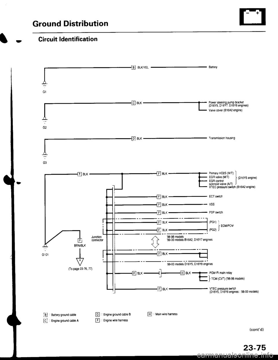
Ground Distribution
Circuit ldentification
(To
I 8an6ry ground cable
: Engine ground caue A
Primary HO2S (M/I) IEGR valve (,tffT) | {Ot6y5 engtne)EGB conrol Isllenoid va ve (vT) lwEc flessure switdr (Bl6A2engine)
vss
PSP swtch
Baaery
BLK -* bqiu"trl'ff lso",ilE o;l?f ;".,L ur,u" "ou.,,r,oo, "*'n",
Trlnsmission ho!gng
BLK
BLK
BLK
BRN/BLK
I
I
Vp?oe 23-76, 77)
'96-98 models'99-00 models 816A2, D16Y7 engines
99-00 modors D16Y5, D16Y8 engines
s,-( -i-t;lBL(- pcM Frman reray' E ) tc" 't*' tn''n''*t'''
wEC pressurc sMch(016Y5, D16Y8 engines : 98-00 models)
@
E
Efal
i Engine grcund cable B
: Engrne wire hamess
(cont'd)
23-75
El , M"in ttire hatn"."
Page 1840 of 2189

Ground-to-Components I ndex
f.,lONOTE: All ground wires are BLK unless otherwise noted.
GroundPageComponents or Circuit Grounded
Battery (BLKYEL)
Steering pump bracket
t+-rg ITransmission housing
l
G101
(-1)
G101
(-2)
14-2
and
14-3
ano
14-1
Powertrain or engine control module (PG1 and pG2 are BLK: LG1 and LG2 are
BRN/BLK), EGR control solenoid valve (CW, EGR valve and lift sensor (Dt6yS enginewith M,/T), Engine coolant temperature switch, pGM-Fl main relay, power steeringpressure switch (USA), Primary HO2S (D16Y5 engine with l\/,/T), Vehicle speed sensor,VTEC pressure switch (D16Y5/D16Y8 engines), CKF sensor (BRN/BLK), Transmission
control module (CYf) (Pc1 is BLK: LG1 is BRN/BLK)
Shielding betvveen the PCM or ECM and these components (all have BRN/BLK wires):
CKF sensor, TDC/CKP/CYP sensor. Primary and secondary heated oxygen sensors.
Knock sensor (CWDl6YB engine), Mainshaft speed sensor (AiT except CVT),
I Countershaft speed sensor (A/T except CVf)
Shielding between the TCM and these components (CVT) (all have BRN/BLK wires):
Drive pulley speed sensor, Driven pulley speed sensor, Secondary gear shaft
speed sensor
Powertrain or engine control module (PG1 and pG2 are BLK; LG1 and LGz are
BRN/BLK), EGR control solenoid valve (D16Y5 engine), EGR valve (Dt685), Engine
coolant temperature switch, Fuel pressure regulator shut-off solenoid valve (D1685),
PGM-FI main relay, Power steering pressure switch (USA), Vehicle speed sensor, VTECpressure switch (All except D16Y7 engine), CKF sensor (A
except 81642) (BRN/BLK)
Shielding between the PCM or ECM and these components (all have BRN/BLK wires):
CKF sensor, TDC/CKP/CYP sensor, Primary and secondary heated oxygen sensors,
Knock sensor (All except D16Y7 engine), i/ainshaft speed sensor (Arf except CW),
Countershaft speed sensor (A,/T except CVf), Drive pulley speed sensor (CW), Drivenpulley speed sensor (CVT), Secondary gear shaft speed sensor (CVf)
I Badiator fan motor, Right front parking/turn signat tight, Right headtight
G20214-4I Cruise control actuator, Left front parking/turn signal lights, Left headlight, Rear window
I washer motor, Windshield washer motor, Washer fluid level switch (,99-'00 Canada)
G401| +-o
and
14-7
Accessory power socket, Brake fluid level switch, Clutch interlock switch (M/T), Clutchswitch (lillT with cruise/D16Y5 engine with MfD, Combination wiper switch (Z wires),
Cruise control main switch, Cruise control unit, Dash lights brightness controller, Data
link connector, Daytime running lights control unit (Canada), Gauge assembly, Horn('96-'97 models), Integrated control unit, Interlock control unit (ArI), Keyless door lock
control unit ('99-'00 models with keyless), Moonroof close and open relays, Moonroof
switch, Park pin switch (A/r), Power window relay, Rear window defogger relay, Rear
window defogger switch ('96-'98 models), Steering lock, Stereo radio tuner (,96-,98
USA: LX, EX, and HX), Turn signal/hazard relay, Windshield wiper motor.....plus
everything grounded through G402
6-6