Page 159 of 2189
Gylinder Head/Valve Train
816A2 engine
Special Tools ............. 6'50 Rocker Arms
VTEC Contlol System
Troubfeshooting Flowchart ............ 6-51 Disassembly/Reassembly ...............6'72
VTEC Solenoid ValveRocker Arms and Lost Motion Assemblies
Inspection ...""'...... 5-54 Inspection .........""' 6-73
VTEC Rocker ArmsRocker Arms and Shafts
Manual Inspection ........................... 6-54 Clearance Inspection ..'..."'.............. 6-74
Inspection Using Special Tools .....' 6-55 Camshafts
Valve Clearance
.^ Adiustment .........." 6-57 Valves'Valve Springs and Valve Seals
. t Crankshaft Pulley and Pulley Bolt Removal """"""""' 6-77
Replacement ..".....6-59 Valve Seats
Timing BeltReconditioning ......6'78
Cylinder Headlnstallation '............ 6-82
Page 164 of 2189
VTEC Solenoid ValveVTEC Rocker Arms
a
I
(
Inspection
1. Remove the VTEC solenoid valve assembly fromthe cylinder head. and check the VTEC solenoidvalve filter for clogging.
. lf there is clogging, replace the engine oilfilter andengine oil.
6x1.0mm12 N.m (1.2 kgf.m, B,7 tbf.ftl
lf the filter is not clogged. push the VTEC solenoidvalve with your finger and check its movemenr.
. lf the VTEC solenoid valve is normal, check theengine oil pressure.
6x1.0mm12 N.m (1.2 kgtm,8.7 lbt.ft)
6-54
L-
SOLENOID
Manual Inspection
1. Set the No. 1 piston at TDC.
2. Remove the ignition wire cover and the wires.
3. Remove the ignition clamps while pulling up on theIock.
6xl.0mm9.8 N.m (1.0 kgl.m, 7.2 tbtftl
IGNITIONWIRE COVER
IGNITIONWIRE
\
LOCK
Page 165 of 2189

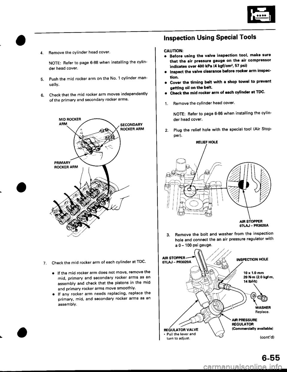
Remove the cylinder head cover.
NOTE: Refer to page 6-88 when installing the cylin-
der head cover.
Push the mid rocker arm on the No. 1 cylinder man-
ually.
Check that the mid rocker arm moves independently
of the primary and secondary rocker arms.
Check the mid rocker arm ot each cylinder at TDC'
. lf the mid rocker arm does not move, removs the
mid, primary and secondary rocker arms as an
assembly and check that the pistons in the mid
and primary rocker arms move smoothly.
. lf any rocker arm needs replacing, replace the
primary. mid, and secondary rocker arms as an
assembly.
7.
2. Plug the
per).
Inspection Using SPecial Tools
CAUTION:
. B€fore using tho Yalvo inspeciion tool, mako suro
that ths air pre3sure gauge on the air comprossor
indicatos ovor /rco kPa (,1 kgf/cm'�, 57 psi)
. In3poct ths valve closranca bafore rock$ arm impoc'
tion.
. Cover the timing beh whh I shop towel to prcvenl
gstting oil on the bolt'
. Chock ths mid rocker arm of each cylindll at TDC'
1. Remove the cYlinder head cover.
NOTE: Rsfer to page 6-86 when installing the cylin-
der head cover.
relief hole with the special tool (Air Stop-
OTLA' - PRSO2OA
3. Remove the bolt and washer from the inspection
hole and connoct the an air pressure regulator with
a 0 - 100 psi gauge.
AIF STOPPEBTNSPECTION HOIEOTLA' - PR3O2OA
t0 x 1.0 mrn20 N.m {2.0 kgf m,14 tbt'fr)
AIR PRESSUREREGULATOR{Cornm.rcirlly avril.bl.lBEGULATOR VALVE. Pull the lever andturn to adjust.{cont'd}
6-55
Page 167 of 2189

Valve Glearance
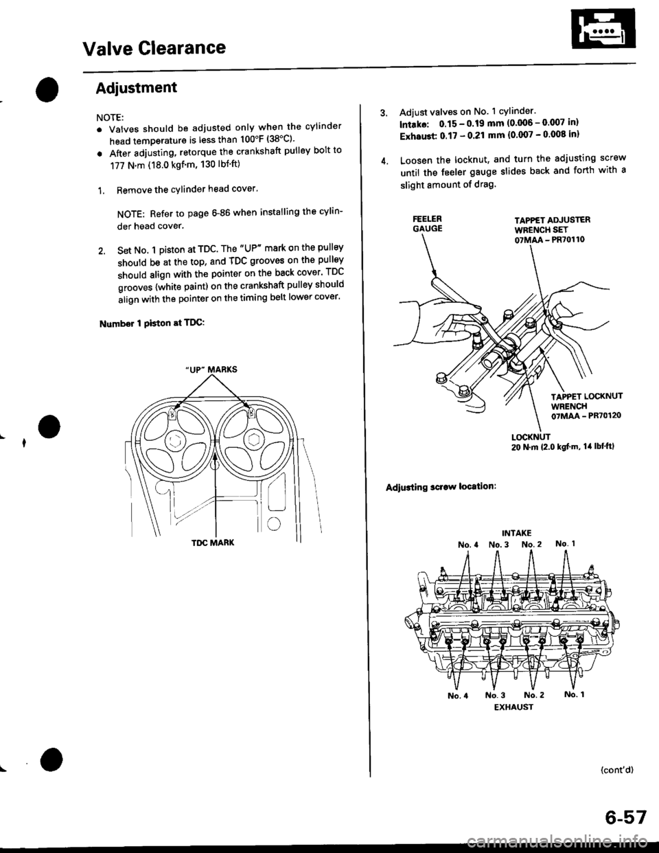
Adjustment
NOTE:
. Valves should be adjusted only when the cylinder
head temperaturs is less than 100'F (38'C)'
. After adjusting, retorque the crankshaft pulley bolt to
177 N.m (18.0 kgf'm, 130 lbt'ft)
1. Remove the cylinder head cover'
NOTE: Refer to page G86 when installing the cylin-
der head cover.
2. Set No. 1 pi$on at TDC. The "UP" mark on the pullsy
should be at the top, and TDC grooves on the pulley
should align with the pointer on the back cover' TDC
grooves {white paint) on the crankshaft pulley should
align with the pointer on the timing belt lower cover'
Number I Piston at TDC:
4.
Adjust valves on No. 1 cylinder.
lntako: 0.15 - 0.19 mm {0'006 - 0.007 in)
ExhaGt 0.17 - 0.21 mm {0'007 - 0 008 inl
Loosen the locknut, and turn the adjusting screw
until the feeler gauge slides back and forth with a
slight amount of drag.
TAPPET ADJUSTERWFENCH SET07MM - PR70110
TAPPET LOCKNUTWRENCH07MAA - PR70120
Adiusting sclaw location:
LOCKNUT20 N.m {2.0 kgf'm, lil lbt'ftl
(cont'd)
6-57
Page 168 of 2189
Valve Clearance
I
I
I
Adjustment {cont'd)
5. Tighten the locknut and recheck clearance.Repeat adjustment if necessary.
Rotate the crankshaft 180. counterclockwise(camshaft pulley turns 90'). The "Up" mark shouldbe on the exhaust side. Adjust valves on No. 3 cylin-der.
Number 3 piston at TDC:
FE€LER GAUGE
"UP- MARKS
6-58
7. Rotate the crankshaft '180. counterclockwise tobring No. 4 piston to TDC. The ,,Up,. mark shouldbe pointing straight down. Adjust valves on No. 4cylinder.
Number 4 piston at TDC:
8, Rotate the crankshaft 180. counterclockwise tobring No. 2 piston to TDC. The "Up., marks shouldbe on the intake side. Adjust valves on No. 2 cylin_der.
Number 2 piston at TDC:
L
Page 170 of 2189

Timing Belt
lllustrated Index
NOTE:
. Refer to page 6-59 for positioning crankshaft and pulley before installing belt.. Mark the direction of rotation on the belt before removino.a Do not use the middle cover and lower cover for storing r'emoved items.. Clean the middle cover and lower cover before installation.
WASHER
I
Replace when damagedor deteriorated.CAP NUTx 1,0 mm9.8 N.m lr.0 kgf.m, 7.2lbtftl
CYLINDERHEAD COVERRefer to page 6-86when installing.
HEAD COVER GASKETReplace when leaking,damaged or deteriorated.Apply liquid gasket atthe four corners ol therecesses,
TIMING BELTInspection, page 6-61Adjustment, page 6-61Replacement, page 6-62
I
6 x '1.0 mm9.8 N.m {1.0 kgf.m, 7.2 lbt.ftl
l0 x 1.25 mm5a N.m {5.5 kgl.m,40 tbt ftt
MIDDTE COVER
6 x 1.0 mrn9.8 N.m {1.0 kgf.m,7.2 tbt-ltl
8 x 1.25 mmN.m {5.7 kgt.m,41 tbt fr)
6x1.0mmN.m 11.0 kgf.m,7.2 tbt.ft'l
PULLEY BOLT14 x 1.25 mm177 N.m {18.0 kgf.m. 130 tbt.ft}Beplacement, page 6-59Do not use an impactwrench when installing.
TIMING BELTDRIVE PULLEY
Installwith concavesurtace facing out.Remove any oil and clean.
LOWERCOVER
CRANKSHAFT PULLEYReplacement, page 6-59
- -o
6-60
Replacement, page 6-59
Page 171 of 2189

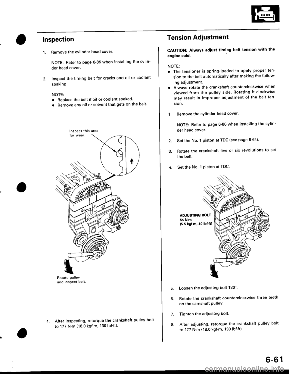
Inspection
Remove the cylinder head cover.
NOTE: Refer to page 6-86 when installing the cylin-
der head cover.
Inspect the timing belt for cracks and oil or coolant
soakrng.
NOTE:
. Replace the belt if oil or coola nt soaked.
. Remove any oil or solvent that gets on the belt'
I
Rotate PUlleYand inspect belt-
After inspecting, retorque the crankshaft pul
to 177 N.m (18.0 kgf'm, 130 lbf'ft)
'L
lnspect thrs area
Tension Adiustment
CAUTION: Always adiust timing belt tension with the
engine cold.
NOTE:
. The tensioner is spring-loaded to apply proper ten
sion to the belt automatically after making the follow-
ing adjustment.
. Always rotate the crankshaft counterclockwise when
viewed from the pulley side. Rotating it clockw'se
may result in improper adjustment of the belt ten-
sion.
1, Remove the cylinder head cover.
NOTE; Refer to page 6-86 when installing the cylin-
der head cover.
2. Set the No. 1 piston at TDC (see page 6-64)
3. Rotate the crankshaft live or six revolutions to set
the belt.
4. Set the No. 1 Piston at TDC
ADJUSTING BOLT
54 N.m(5.5 kgt.m, a0 lbtftl
5.
7.
8.
Loosen the adjusting bolt 180'.
Rotate the crankshaft counterclockwise three teeth
on the camshaft PulleY.
Tighten the adjusting bolt.
After adjusting, retorque the crankshaft pulley bolt
to 177 N.m (18.0 kgf'm, 130 lbnft)
ley bolt
6-61
Page 173 of 2189
7.
8.
Remove the crankshaft pulley (see page 6-59).
Remove the cylinder head cover'
NOTE: Refer to page 6-86 when installing the cylin-
der head cover.
Remove the middle cover and lower cover.
NOTE: Do not use the middle and lower covers for
storing removed items.
MIDDLE COVER
LOWER COVER
9.
10.Loosen the adjusting bolt 180'.
to remove tension from the
retighten the adjusting bolt.
9.8 N.m lt.o kgf m,
7.2lw'ftl
Push the tensioner
timing belt, then
N.m (5.5 kgt'm,
1 1. Remove the timing belt.
TDC
lnstallation
Install the timing belt in the reverse order of removal;
Only key points are described here.
1. Set the timing belt drive pulley so that the No. 1 pis'
ton is at top dead center (TDC). Align the groove on
the timing belt drive pulley to the V pointer on the
oil pumP.
set the camshaft pulleys so that the No. 1 piston is at
TDC.
Align the TDC marks on the intake and exhaust cam-
shaft pulleys.
MARK
(cont'd)
6-63
POINTER