1998 HONDA CIVIC Vacuum hose
[x] Cancel search: Vacuum hosePage 1170 of 2189
Front Brake Galiper
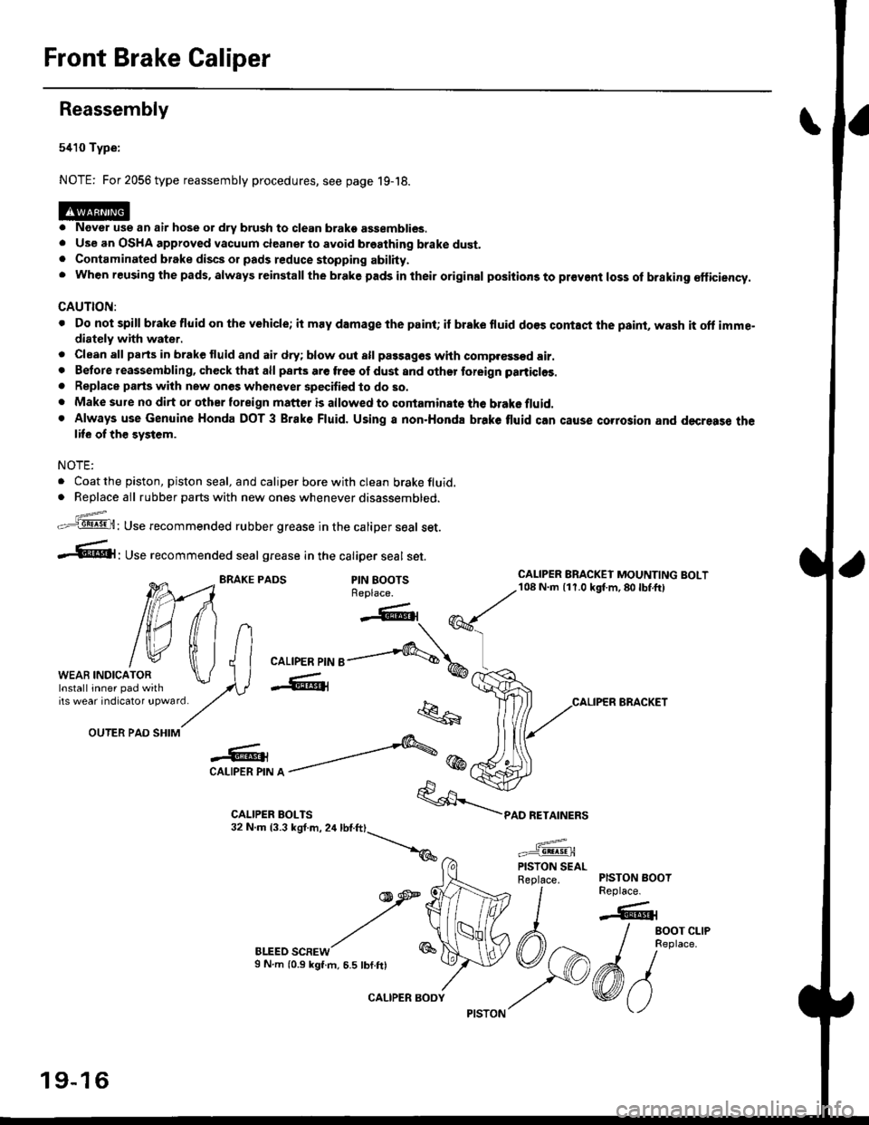
Reassembly
5410 Type:
NOTE: For 2056 type reassembly procedures, see page 19-18.
o Never use an air hose or dry brush to clean brako assemblies.. Use an OSHA approved vacuum cleanerto avoid breathing brake dust.. Contaminated brake discs or pads reduce stopping abilhy.. when reusing the pads, always reinstall the brake pads in their original positions to pr€vent loss of braking €fficiency.
CAUTION:
. Do not spill brake fluid on the vehicle; it may damage the paint; if brake fluid do€s contaci the psint, wash it oft imme"diately with water.
. Clean all parts in brake fluid and air dry; blow out all passag€s whh comp.€ssed air.. Betore reassembling, check that all parts are free ol dust and othor toreign particlos.
. Replace parts wilh new ones whenever specified to do so.. Make sure no dirt or other toreign matt€r is allowed to contaminate the brake fluid.. Always use Genuine Honda DOT 3 Brake Fluid. Using a non.Honda brake tluid can cause corrosion and decresse thelife of th€ system.
NOTE:
. Coat the piston, piston seal, and caliper bore with clean brake fluid.. Replace all rubber parts with new ones whenever disassembled.
z_..=-.q8! .9!,H: Use recommended rubber grease in the caliper seal set.
-.61' use recommended seal grease in the catiper seal set.
BRAKE PADSPIN BOOTSReplace.
OUTER PAD SHIM
-o -'''---&@CAI-IPER PIN A -
BLEED SCREWS N.m (0.9 kgt.m, 6.5 tbf.ftl
"k..6
*/\*
car-rpen prr'r e-....,-q\,
-W@{
q
1
PAD RETAINERS
CALIPER BRACKET
WEAB INDICATOR
tilfliltn
tw tfi lJlWEAB rNDrcAroR \J I Ilnsrall inner pad with lAVirs weat indicatot !pwatd/,.
CALIPER BRACKEI MOUNTING BOLT108 N.m {11.0 kgt m,80lbf.ft)
PISTON BOOTReplace.
-6r
/ eoor cr-re
I neptace.
6/vo
PISTON SEALReplace.
19-16
CALIPER BODY
Page 1172 of 2189
Front Brake Caliper
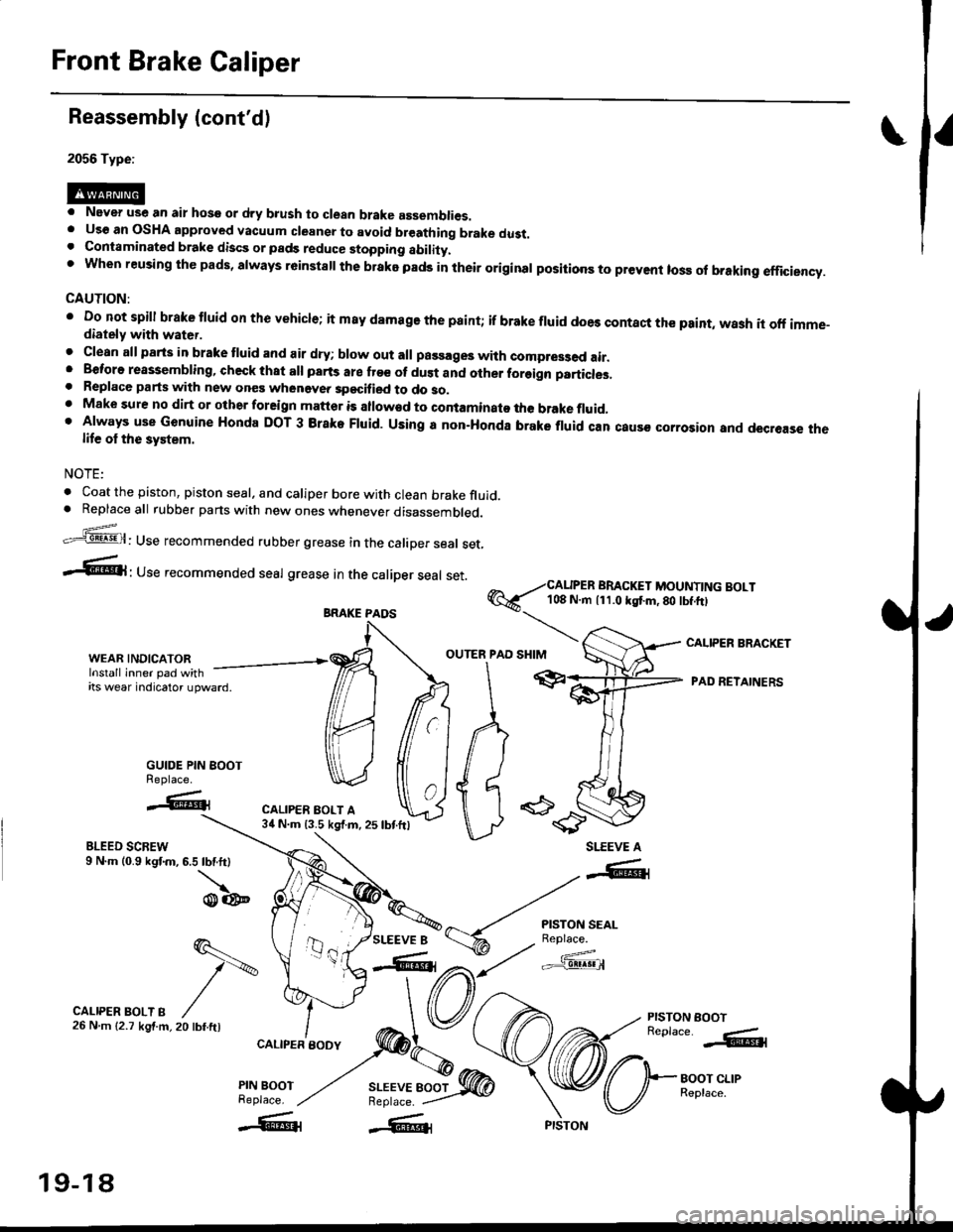
Reassembly (cont'd)
2056 Type:
. Never use an air hose or dry b.ush to clean brake assemblies.. Uso an OSHA approved vacuum cleansr to avoid breathing brake dust.. Contaminated brake discs or pads reduce stopping ability.t when reusing the pads, always r6instsll the brake pads in their original positioos to prevent loss ol braking efficiency.
CAUTION:
' Do not spill brake tluid or th€ vehicle; it m8y damage the paint; if brake fluid does contact the paint, wash it off imme-diately with water.
. Clean all parts in brake tluid and air dry; blow out all passages with compr63ed air.. Beforo reassembling, check that all parts are fr€e of dust and other foreign particles,. Replace parts with new ones whenevea specified to do so.. Make sure no dirt or other foreign matter is allowad to contaminato the brake fluid,' Always use Genuine Honda DOT 3 Brake Fluid. Using a non-Honda brake fluid can caus€ corrosior and decrease thelife ol the system.
NOTE:
. Coat the piston, piston seal, and caliper bore with clean brake fluid.. Replaceall rubber parts with new ones whenever disassembled.
.'=5@: Use recommended rubber grease in the caliper seal set,
-6l ' Use recommended seal grease In the caliper seal set.
@6--i#i['i,?li"..;:l]l?Y]li"'"'
I
r""'"rr r"""ip"autr, -/ffr
e"6ft 'ADRETATNERSitswearndcatoru'ward
MffiA pr
GUIDE PIN BOOT ) {I I II ) I I
% caL,PER
\I\d/ tt ' id 6
u -es'---r..'.* ".-,."oo*'J.l, ru,oonW U
**=*t
WEAR,INDICAToR. ,ffi OUTERIPAD
BLEED SCREW9 N.m (0.9 kgf.m, 6.5 lbf.ft)
\o@
CALIPER BRACKET
PISTON EOOTReplace. -.&l
BOOT CLIPReplace.
SLEEVE A
SLEEVE 8
-"-41
r{.i'""Jg*'
a,t/ c'f3!@
q.-
t\
20 tbf.ftl
CALIPER BOLT B26Nm{2.7kgf.m,
CALIPER BODY
PIN BOOTReplace.
BRAKE PAOS
19-18
Page 1175 of 2189
Master Cylinder/Brake Booster
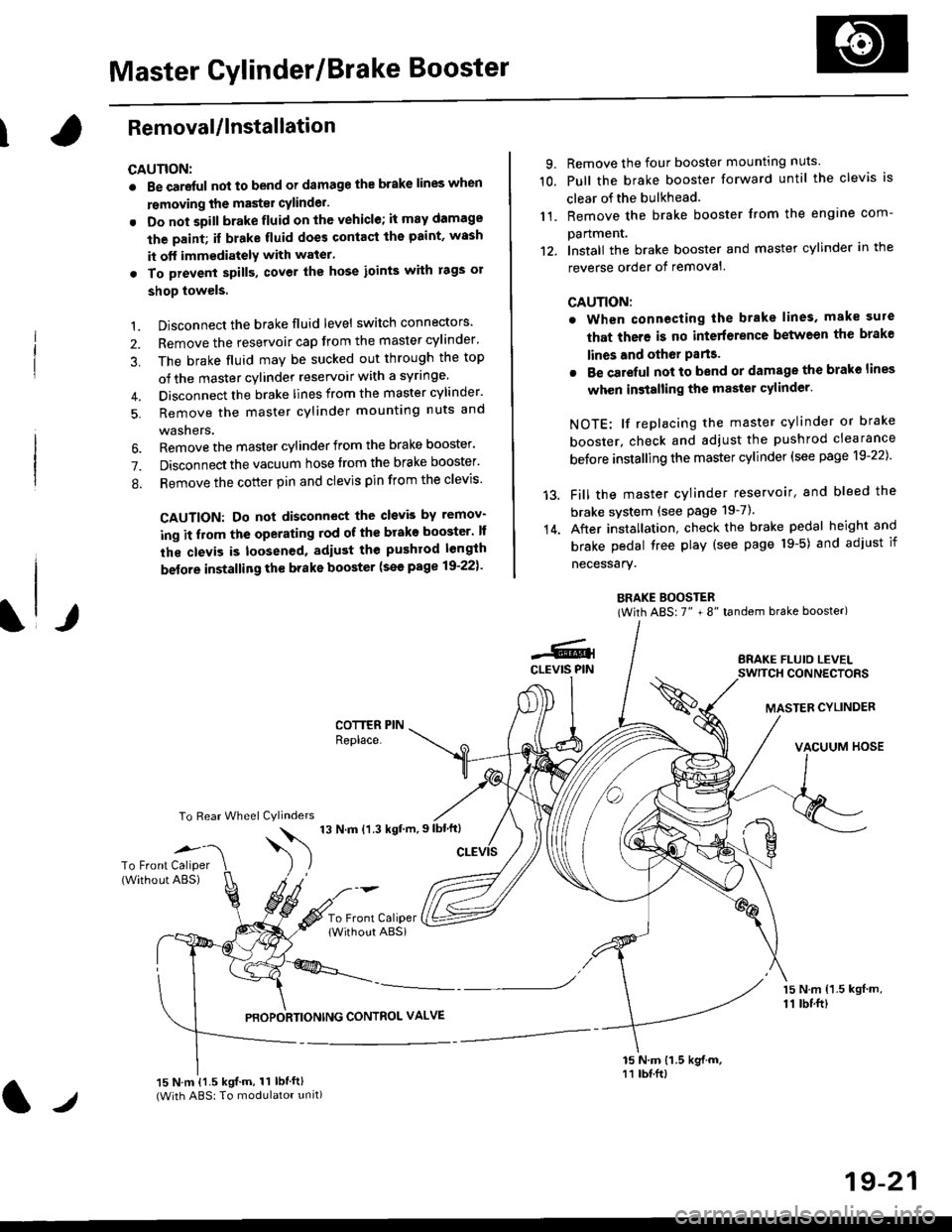
IRemovaUlnstallation
CAUTION:
. Be care{ul nol to bend or damage the brake lines when
rsmoving the mastsr cYlinder.
. Do not soill brakefluid on the vehicle; it may damage
the paint; if brake fluid does contact the paint, wssh
it off immediatelY with water'
. To prevent spill3, cover the hose ioints with rags or
shop towels.
9. Remove the four booster mountlng nuts
10. Pull the brake booster forward until the clevis is
clear of the bulkhead.
11. Remove the brake booster from the engine com-
panmenr.'12. Install the brake booster and master cylinder in the
reverse order of removal.
CAUTION:
. When connecting the brake lines. make sure
that there is no inte erence between the brake
lines and oth6r Parts.
r Be careful not to bend or damage the brake lines
when installing the master cylinder.
NOTE: lf replacing the master cylinder or brake
booster, check and adiust the pushrod clearance
be{ore installing the master cylinder (see page 19-221'
Fill the master cylinder reservoir, and bleed the
brake svstem (see Page 19-7).
After installation. check the brake pedal height and
brake pedal tree play (see page l9-5) and adjust if
necessary.
BRAKE BOOSTER(With ABS: 7" + 8" tandem brake booster)
BRAKE FLUIO LEVELSWITCH CONNECTORS
MASTER CYLINDER
VACUUM HOSE
1.
2.
3,
5.
Disconnect the brake fluid level switch connectors'
Remove the reservoir cap from the master cylinder'
The brake fluid may be sucked out through the top
of the master cylinder reservoir with a syrlnge.
Disconnect the brake lines from the master cylinder'
Remove the master cylinder mounting nuts and
washers.
\l/
6. Remove the master cylinder from the brake booster'
7. Disconnect the vacuum hose trom the brake booster'
8. Remove the cotter pin and clevis pin from the clevis'
CAUTION: Do not disconnect the clevb by remov-
ing it from the operating rod of the brako booster' lf
the clevis is loosened, adiust the pushrod length
before installing th€ brake booster (see page 19-221'
COTTER PINReplace.
To Rear Wheel Cylinders
14.
-6.4CLEVIS PIN
To Front Caliper(Without ABS)$
t'N't'ttrnt'-''
To Front CaliperlWithout ABSi
PBOPORTIONING CONTROL VALVE
15 N.m {1.5 kgl m,11 tbtft)
15 N.m {1.5 kgif.m, 11 lbtft}(With ABS: To modulator unit)lr
19-21
Page 1177 of 2189
Brake Booster InsPection
FunctionalTest
1. With the engine stopped, depress the brake pedal
several times to deplete the vacuum reservoir, then
depress the pedal hard and hold it for 15 seconds lf
the pedal sinks' either the master cYlinder is
bypassing internally, or the brake system (master
cylinder. lines. modulator, proportioning control
valve, or caliPer) is ieaking.
2. Start the engine with the pedal depressed lf the
pedal sinks slightly, the vacuum booster is operating
normally. lf the pedal height does not vary, the
booster or check valve is faultY.
3. With the engine running. depress the brake pedal
lightly. Apply just enough pressure to hold back
automatic transmission creep. lf the brake pedal
sinks more than 25 mm (1.0 in.) in three minutes,
the master cvlinder is faulty. A slight change in
pedal height when the A'lC compressor cycles on
and off if normal. (The A/C compressor load
changes the vacuum available to the booster')
Leak Test
1. Depress the brake pedal with the engine running.
then stop the engine. lf the pedal height does not
vary while depressed for 30 seconds, the vacuum
booster is OK. lf the pedal rises. the booster is
faulty.
2, With the engine stopped, depress the brake pedal
several times using normal pressure When the
Dedal is first depressed, it should be low On con-
secutive applications, the pedal height should grad-
uallv rise. lf the pedal position does not vary, checK
the booster check valve.
l./
19-23
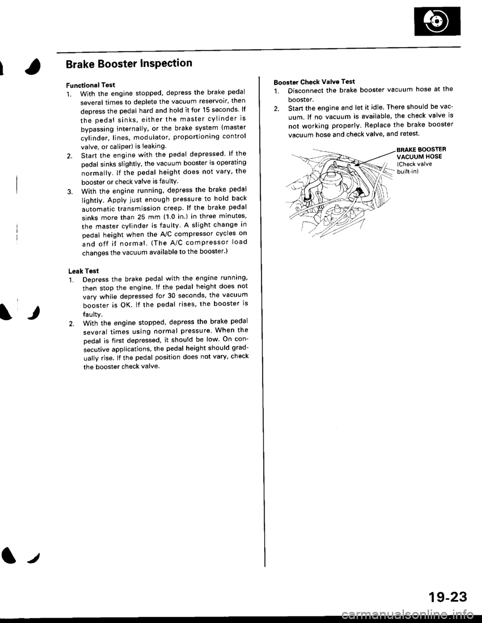
Booster Check Valve Test
1. Disconnect the brake booster vacuum hose at the
booster.
2. Stan the engine and let it idle. There should be vac-
uum. lf no vacuum is available, the check valve is
not working properly. Replace the brake booster
vacuum hose and check valve, and retest.
BRAKE BOOSTERVACUUM HOSE(Check valve
built-in)
Page 1178 of 2189
Rear Brake Pads
Inspection and Replacement
Never use an air hose or dry brush to clean brakeassemblies.
Use an OsHA-apptoved vacuum cl€aner to avoidbreathing brake dust,
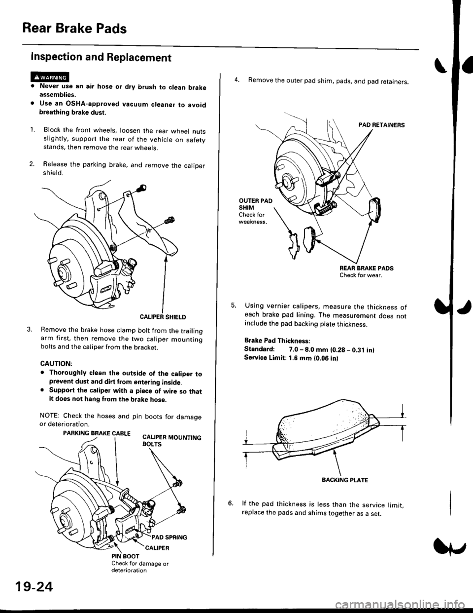
Block the front wheels, loosen the rear wneet nutsslightly, support the rear of the vehicle on safetystands, then remove the rear wheels.
Release the parking brake, and remove the calioersh ield.
CALIPER SHIELD
Remove the brake hose clamp bolt from the trailingarm first, then remove the two caliper mountingbolts and the caliper from the bracket.
CAUTION:
. Thoroughly clean the outside of the caliDer toprevent dust and dirt trom entering inside.. Support the calipor with a pieco of wire so thatit does not hang fuom the brake hose.
NOTEr Check the hoses and pin boots for damageor deterioration.
PARKING BRAKE CABLE ^.. ._-_ ---.
'L
19-24
4. Remove the outer pad shim, pads, and pad retainers.
PAO RETAINERS
OUTER PAOSHIMCheck for
REAR BRAKE PADSCheck for wear.
Using vernier calipers, measure the thickness ofeach brake pad lining. The measurement does notanclude the pad backing plate thickness.
Brake Pad Thickness:
Standard: 7.0 - 8.0 mm {0.28 - 0.31 in}Service Limit: 1.5 mm {0.06 in}
lf the pad thickness is less than the service limit,replace the pads and shims together as a set.
BACKING PI-ATE
Page 1181 of 2189
Rear Brake Caliper
Disassembly
@f l',lever use an air hose or dry brush to clean
assemblies.
. Use an OsHA-approved vacuum cleaner to
brake
avoid
breathing brake dust.
. Contaminated brake discs or pads reduce stopping
ability.
CAUTION:
. Do not spill brake tluid on the cal; h may damage the
paint; if brake fluid does contact the paint, wash ii
ofl immediatelY with water.
. To prevent spills, cover the hose ioints whh rags or
shop tow€ls.
. Clean all parts in brake fluid and air dry; blow out all
passagss with complessed air.
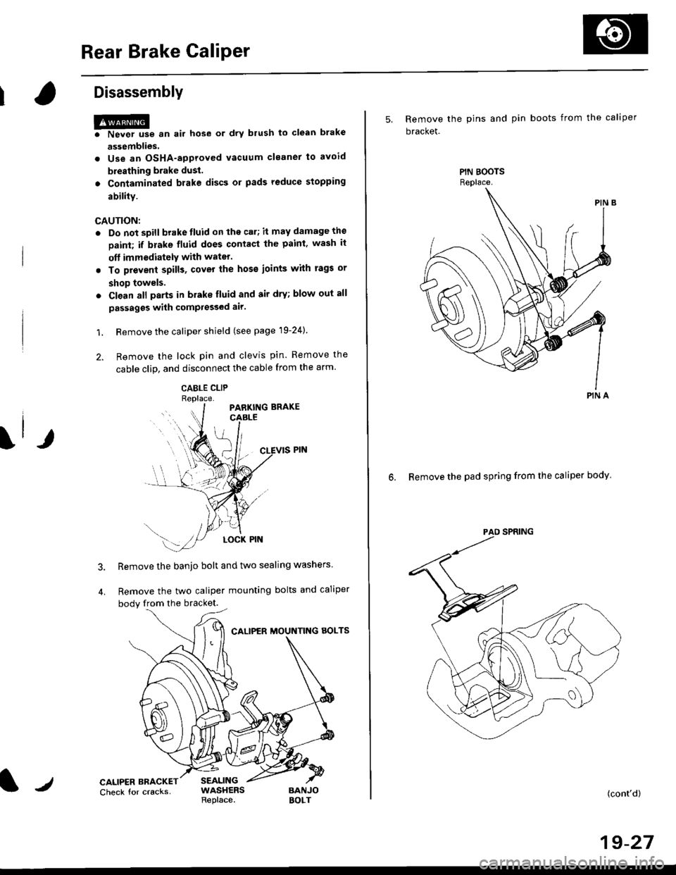
1. Remove the caliper shield (see page 19-24).
2. Remove the lock pin and clevis pin. Remove the
cable clip, and disconnect the cable from the arm
CABLE CLIP
Remove the banjo bolt and two sealing washers
Remove the two caliper mounting bolts and caliper
body from the bracket.
CALIPER MOUNTNG AOLTS
CALIPER BRACKETCheck for cracksSEALINGWASHERSReplace.BANJOBOLT
5, Remove the pins and pin boots from the caliper
bracket.
6. Remove the pad spring from the caliper body
PIN A
(cont'd)
19-27
Page 1189 of 2189
Rear Drum Brake
Index/lnspection
'1.
a
a
Never use an air hose or dly brush to clean brake assemblies,
Use an OSHA approved vacuum cleanar to avoid breathing brake dust,
Contaminated brake linings or drums reduce stopping ability.
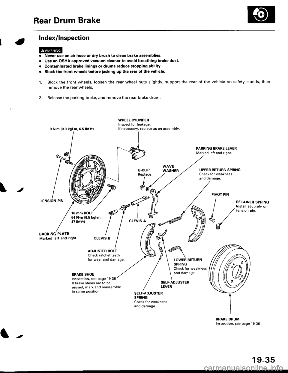
Block the tront wheels before iacking up ths r€ar of lhe vehicle.
Block the front wheels, loosen the rear wheel nuts slightly, support the rear of the vehicle on safety stands, then
remove the rear wheels.
2. Release the parking brake, and remove the rear brake drum.
I N m 10.9 kgtm, 6.5 lbf.ftl
TENSION PIN
10 mm BOLT6,1N m 15.5 kgf m,47 tbf.ft)
WHEEL CYLINDERInspect for leakage.lf necessary, replace as an assembly.
u-cLrPReplace.
WAVEWASHER
PARKING BRAKE LEVERMarked left and right.
Check for weaknessano oamage,
UPPER RETURN SPRING
I
@JPIVOT PIN
BACKING PLATEMarked lelt and right-
/
€f-l.^
I I
*'t")
ctEv'sB
/ (t
/ ,.ro,".r r.*,"n
/ , Install securely on
| / tension pin.
d"/
IU
ADJUSTER BOI-TCheck ratchet teethfor wear and damage.LOWER RETURNSPRINGCheck for weaknessand oamage.BRAKE SHOEInspection, see page 19-36lf brake shoes are to bereused, mark and reassemblein same position.
SELF.ADJUSTERLEVEB
SELF-ADJUSTERSPRINGCheck for weaknessano oamage.
BRAKE DRUMInspection, see page '19 36
t
19-35
Page 1450 of 2189
A/C System Service
Pressure Test Chart
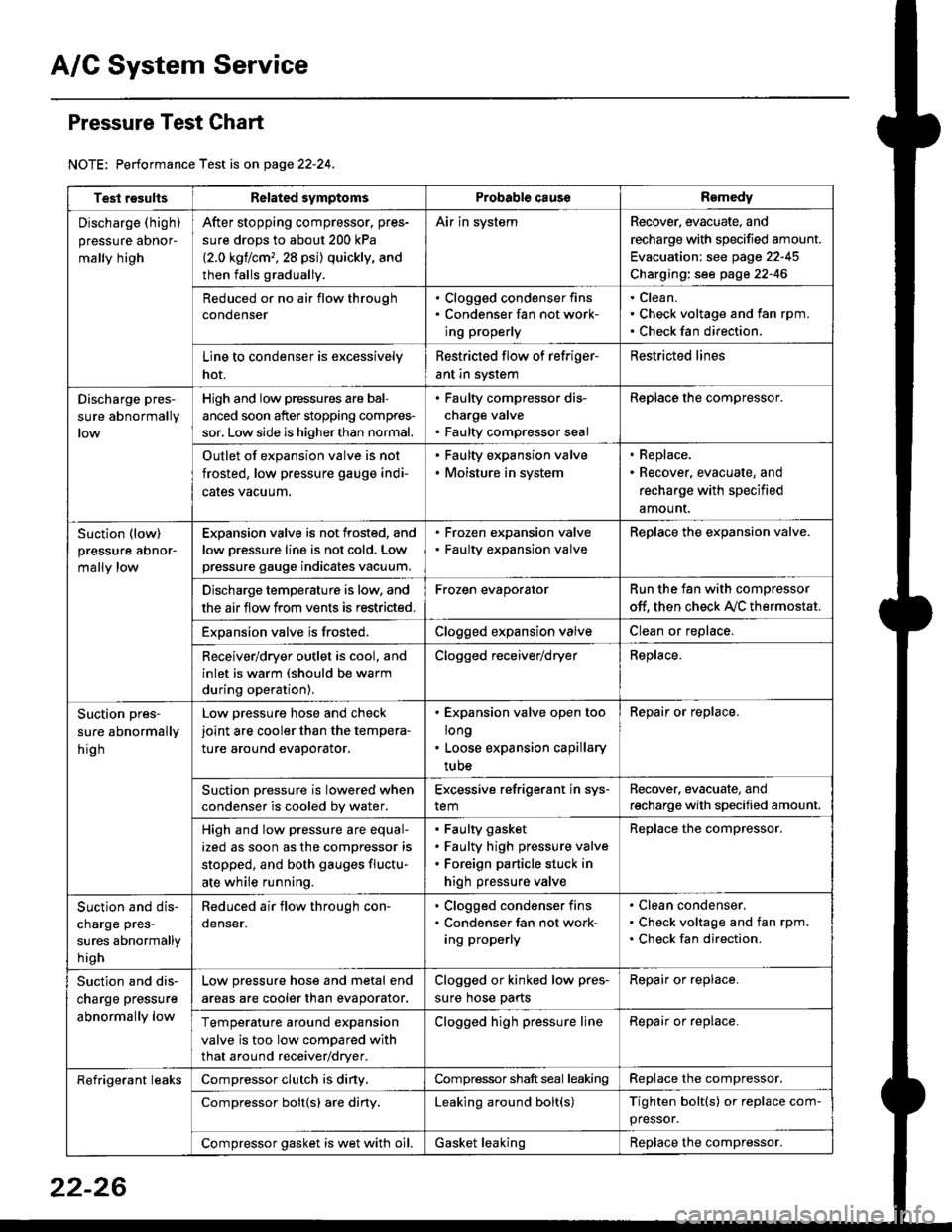
NOTE: Performance Test is on page 22-24,
Test resultsRelated symptomsProbabl€ causeRemedy
Discharge (high)
pressure aDnor-
mally high
After stopping compressor. pres-
sure drops to about 200 kPa
{2.0 kgflcm,,28 psi) quickly, and
then falls gradually.
Air in systemRecover, evacuate, and
recharge with specified amount.
Evacuation: see page 22-45
Charging: see page 22-46
Reduced or no air flow through
condenser
. Clogged condenser fins. Condenser fan not work-
ing properly
Clean.
Check voltage and fan rpm.
Check fan direction.
Line to condenser is excessively
hot.
Restricted flow of refriger-
ant in system
Restricted lines
Discharge pres-
sure abnormally
High and low pressures are bal-
anced soon after stopping compres-
sor, Low side is higher than normal.
. Faulty compressor dis-
charge valve. Faulty compressor seal
Replace the compressor.
Outlet of expansion valve is not
frosted, low pressure gauge indi-
cales vacuum.
. Faulty expansion valve. Moisture in system
. Replace,. Recover, evacuate, and
recharge with specified
amount.
Suction (low)
pressure abnor-
mally low
Expansion valve is not frosted, and
low oressure line is not cold. Low
pressure gauge indicates vacuum.
. Frozen expansion valve. Faulty expansion valve
ReDlace the exoansion valve.
Discharge temperature is low. and
the air flow from vents is restricted.
Frozen evaporatorRun the fan with compressor
off. then check A,/C thermostat.
Exoansion valve is frosted.Clogged expansion valveClean or replace.
Receiver/dryer outlet is cool, and
inlet is warm (should be warm
during operation).
Clogged receiver/dryerReplace.
Suction pres-
sure abnormally
hig h
Low pressure hose and check
joint are cooler than the tempera-
ture around evaporator.
. Expansion valve open too
long. Loose expansion capillary
tube
Repair or replace.
Suction oressure is lowered when
condenser is cooled bv water.
Excessive refrigerant in sys-
tem
Recover. evacuate, and
recharge with specified amount.
High and low pressure are equal-
ized as soon as the compressor is
stopped, and both gauges fluctu-
ate while running.
Faulty gasket
Faulty high pressure valve
Foreign particle stuck in
high pressure valve
Replace the compressor.
Suction and dis-
charge pres-
sures abnormally
h igh
Reduced air flow through con-
denser.
. Clogged condenser fins. Condenser fan not work-
ing properly
Clean condenser.
Check voltage and fan rpm.
Check fan direction.
Suction and dis-
charge pressure
abnormally low
Low pressure hose and metal end
areas are cooler than evaporator.
Clogged or kinked low pres-
sure hose parts
Repair or replace.
Temperature around expansion
valve is too low compared with
that around receiver/dryer.
Clogged high pressure lineRepair or replace.
Refrigerant leaksCompressor clutch is diny,Compressor shaft seal leakingReplace the compressor.
Compressor bolt{s) are diny.Leaking around bolt(s)Tighten bolt(s) or replace com-
pressor.
Compressor gasket is wet with oil.Gasket leakingReplace the compressor.
22-26