1998 HONDA CIVIC IGNITION SWITCH ASSEMBLY
[x] Cancel search: IGNITION SWITCH ASSEMBLYPage 1774 of 2189
Troubleshooting
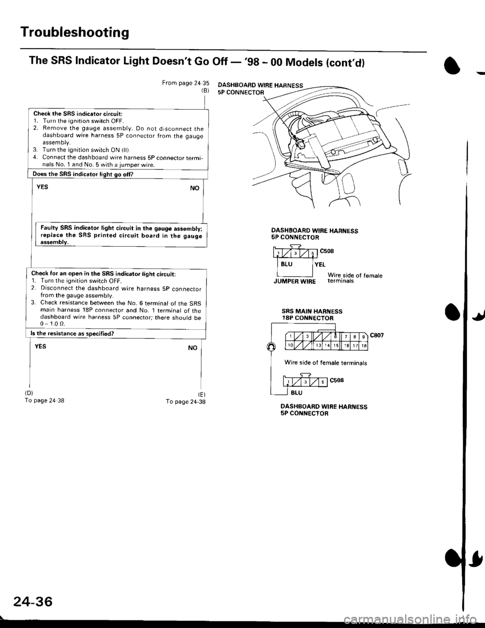
The SRS Indicator Light Doesn't Go Off - '98 - 00 Models (cont,dl
From page 24 351B)
Check the SRS indicetor circuit:1. Turn the ignition switch OFF.2. Bemove the gauge assembly, Do not dlsconnect thedashboard wire harness 5P connector from the gaugeassemoly.3. Turn the ignition switch ON (ll)4. Connect the dashboard wire harness 5P connector termi-nals No. 1 and No. 5 with a jumper wire.
Does the SRS indicator light go om
YESNO
Faulty SRS indicator light circuit in the 9au96 assembly;replace the SRS printed circuit board in the gaugeessembly.
Check for an open in the SRS indicator light circuit:r. rurn rne rqnrton swrtch ut-t-.2. Disconnect the dashboard wire harness 5p connectorfrom the gauge assembly.3. Check resistance between the No. 6 terminal of the SBSmain harness 18P connector and No. I terminal of thedashboard wire harness 5P connector; there should be0 1.0 0.
ls the resistance as soecified?
NOYES
(D)
To page 24 38(E)To page 24-38DASHBOARD WIRE HARNESS5P CONNECTOR
OASHBOARD WIRE HAR'{ESS5P CONNECTOR
llTf;rv;1c508.1#
I Bru lYErWire side of femaleJUMpER WIRE rerminats
SRS MAIN HARi{ESSI8P CONNECTOR
c807
24-36
DASHBOAED WIRE HARNESS
Wire side of female terminals
Page 1786 of 2189
Troubleshooting
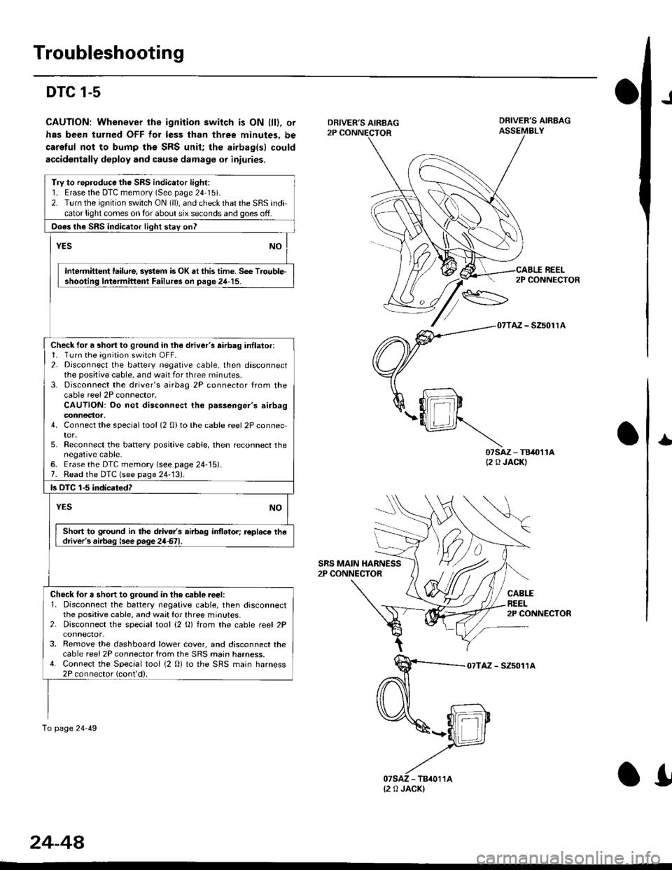
DTC 1-5
CAUTION: Whenever the ignition switch is ON {ll). or
has been turned OFF for less than three minutes, be
caretul not to bump ths SRS unit; the airbag(sl could
accidentally deploy and cause damage or iniuries.
J
DRIVER'S AIRBAG2P CONNECTOR
SRS MAIN HARNESS2P CONNECTOR
DRIVER'S AIRBAGASSEMBLY
REEL
07sAz - TB40't1A(2 0 JACK)
2P CONNECTOR
AZ - SZ5011A
CABLEREEL2P CONNECTOR
I
07TAZ - SZ5011A
Try to rep.oduce the SRS indicator light:1. Erasethe DTC memorv (See page 24'15).2. Turn the ignition switch ON (ll), and check that the SRS indicator light comes on tor about six seconds and goes off.
Ooes the SRS indicator light stay onl
YESNO
Intermittent lailure, system is OK at this time. See Trouble-shooting lntormittent Failure3 on page 24-15.
Check for a short to ground in lh€ driver's airbag inllator:1. Turn the ignition switch OFF.2. Disconnect the battery negative cable, then disconnectthe positive cable, and wait for three rninutes.3. Disconnect the driver's airbag 2P connector from thecable reel 2P connector.CAUTION: Do not disconnect tho p.ssenger's airbagconnectoa.4. Connect the specialtool (2 0)to the cable reel 2P connector.5. Reconnect the batlery positive cable, then reconnect thenegative cable-6. Erase the DTC memory (see page 24-15).7. Read the DTC (see page 24-131.
ls OTC 1-5 indicatedT
YESNO
Short to ground in the drive/s airbeg inflator; r€pl.ce thedriver's.iib.g (see page 24d1.
Check lor a short to ground in the csble reer:l. Disconnect the battery negative cable, then disconnectthe positive cable, and wait for three minutes.2. Disconnect the special tool {2 (}) from the cable reel 2P
3. Remove the dashboard lower cover, and disconnect thecable reel 2P connector from the SRS main harness.4. Connect the Special tool {2 0} to the SRS main harness2P connector (cont'd).
To page 24-49
{2 0 JACK)
24-44
.I
Page 1819 of 2189
How To Use This Manual
Circuit Schematics
oa
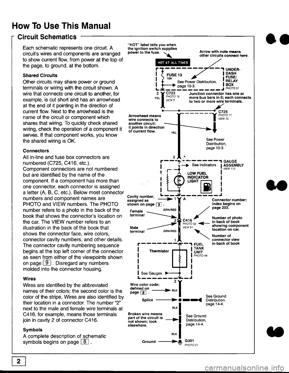
Each schematic represents one circult. A
circuit's wires and components are arranged
to show current flow, from power at the top of
the page, to ground, at the bottom.
Shared Circuits
Other circuits may share power or ground
terminals or wiring with the circuit shown. A
wire that connects one circuit to another, for
example, is cut short and has an arrowhead
at the end of it pointing in the direction of
current flow. Nelit to the anowhead is the
name o{ the circuil or comoonent which
shares that wiring. To quickly check shared
wiring, check the operation of a component it
serves. lf that component works, you know
the shared wiring is OK.
Connectors
All in-line and fuse box connectors are
numbered (C725, C416, etc.).
Component connectors are not numbered
but are identiJied by the name of the
component. lf a componenl has more than
one connector, each connector is assigned
a letter (A, B, C, etc.). Below most connector
numbers and comDonent names are
PHOTO and VIEW numbers. The PHOTO
number refers to a Dhoto in the back of the
book that shows lhe conneclor's location on
the car. The VIEW number refers to an
illustration in the back of the book that
shows the connector face, wire colors,
connector cavity numbers, and other details.
The connector cavity numbering sequence
begins at the top left corner oJ the connector
as seen from either of the viewooints shown
on page ffl . Disregard any numbers
molded into the connector housino.
Wires
Wires are identilied by the abbreviated
names of their colors; the second color rs the
color of the stripe. Wires are also identified by
their location in a connector. The number '2"
next to the male and female wire terminals at
C416, for example, means those terminals
join in cavity 2 of connector C416.
Symbols
A complete description of schematic
symbols begins on page | 8
"HOT" label tells you whenthe ignition switch suppliespower to the fuse. \
Artowhead meanswire connects toanother circuit;
Arrow with note rErngother circuils conncct h€re.
it .a
llu":: ^,{ ii t See Power Distribution, .I t----t oaqe tO-3. IL*--:--------J2 Y C723 Junction connectorYEL I Pao'o'8 more bus bars in it;
I - " " to two or more wire
l,/
-t>?
See PowerDistribution,page 10-3.
UNDER.DASHFUSE/RELAYBOX
has one oleach connactgterminala.
it ooints in directionof current flow.
TheImletor
t_I
Cavity number; L ---
Jiili'iJi!--' -----> '
shoin on page S .
Maleterminal
L?*?l?,-
"'"'I
c725
vlEUt/ 75
Connector number;index begins onpage 203.
Number ot photoin back ol bookshowing componentlocation on cat.
Number ofconneclor viewin back of book
7
GBN/FEO
See Ground
Soe Indicators I ASSEMBLY
:-------J
LOW FUELINDICATOFLIGHT r-l
EI
A
"o'r"/PHOTO 52 <-
\
FUELTANKUNIT
Splice ---------) O rr
".* I Page 14'4'
IBroken wire means | --^ -
iar";J.'It,;,rJ;ii; -----i Bffi,Bili*l
elsewhere. I 0a0e tn-a
IBrK Icround --->lL c301: ptioro 21
Page 1980 of 2189
Gauges (cont'd)
- How the Gircuit Works
When the ignition switch is in ON (ll) or START (lll),
battery voltage is supplied through fuse 25 to the
gauges in the gauge assembly.
Speedometer and Odometer
The odometer and soeedometer drive circuits
receive pulses from the vehicle speed sensor
(VSS). The pulse rate increases as the car
accelerates. The frequency and duration of these
input pulses are measured and displayed by the
speedometer, odometer and tripmeter.
Tachometer
The tachometer drive circuit receives pulses from
the ignition control module (lCM) in the distributor
assembly or the ECM/PCM. The solid-state
lachometer then displays these pulses as engine
speed. For each 200 pulses per minute from the
ignition control modul€ (lCM) or the ECM/PCM, the
tachometer displays 100 RPM.
Engine Coolant Temperature Gauge
The engine coolant temperature gauge has two
intersecting coils wound around a permanent
magnet rotor. Voltage applied to the coils, through
fuse 25, generates a magnetic lield. The magnetic
field, controlled by the coolant temperature sending
unit, causes the rotor to rotate and the gauge
needle to move. As the resistance in the sending
unit varies, current through the gauge coils
changes. The gauge needle moves toward the coil
with the strongest magnetic field.
The 6ngine coolant temperature sending unit's
resistance varies from about 137 ohms at low
engine temperature to between 3H6 ohms at high
temperature (radiator fan running).
Refer to the Service Manual (Section 23, Electrical)
for specific tests or troubleshooting procedures.
81-2
(
Fuel Gauge (All except cX)
The fuel gauge has two intersecting coils wound
around a permanent magnet rotor. Voltage applied
to the coils, through tuse 25, generates a magnetic
field. The magnetic field, controlled by the fuel
gauge sending unit, causes the rotor to rotate and
the gauge needle to move. As the resislance in the
sending unit varies, current through the gauge coils
changes. The gauge needle moves toward the coil
with the strongest magnetic field.
The fuel gauge sending unit's resistance varies
from about 2-5 ohms at full, to about 110 ohms at
empty. When you turn the ignition switch off, the
gauge remains at the last reading until you turn the
ignition switch to ON (ll) or START (lll) again,
Refer to the Service Manual (Section 23, Electrical)
for specific tests or troubleshooting procedures.
Fuel Gauge (GX)
The fuel gauge has two intersecting coils wound
around a permanent magnet rotor. Voltage applied
to the coils, through fuse 25, generates a magnetic
field. The magnetic field, controlled by the PCM,
causes the rotor to rotate and the gauge needle to
move. The PCM calculates the gas quantity in the
fuel tank by using the fuel pressure value detected
by the tuel tank pressure sensor and the fuel
temperature value detected by the fuel tank
temperalure sensor, and outputs the signal to the
gauge assembly. The gauge needle moves toward
the coil with the strongest magnetic field.
When you turn the ignition switch off , the gauge
remains at the last reading until you turn the ignition
switch to ON (ll) or START (lll) again. When the
PCM detects a malfunction with the fuel pressure or
temperature, or detects a gas leak, the PCM
reduces the fuel meter to 0.
Refer to the Service Manual GX Supplement
(Section 11 , Fuel and Emissions) for specific tests
or troubleshooting procedures.
a
a
Page 2060 of 2189
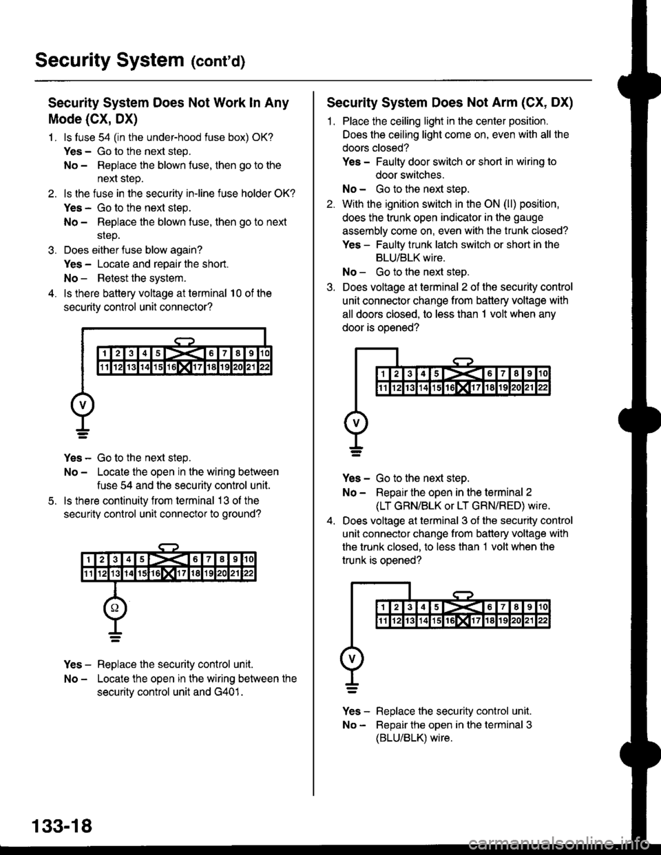
Security System (cont'd)
Security System Does Not Work ln Any
Mode (CX, DX)
1. ls luse 54 (in the under-hood fuse box) OK?
Yes - Go to the next step.
No - Repiace the blown fuse, then go to the
next step.
2. ls the fuse in the securiiy in-line fuse holder OK?
Yes - Go to the next step.
No - Replace the blown fuse, then go to next
srep.
3. Does either fuse blow again?
Yes - Locate and repair the short.
No - Retest the system.
4. ls there battery voltage at terminal 10 of the
security control unit connector?
Yes - Go to the next step.
No - Locate the open in the wiring between
fuse 54 and the security control unit.
ls there continuity from terminal 13 ol the
security control unit connector to ground?
Yes - Replace the security control unit.
No - Locate the open in the wiring between the
securitv control unit and G401.
5.
133-18
Security System Does Not Arm (CX, DX)
1. Place the ceiling light in the center position.
Does the ceiling light come on, even with all the
doors closed?
Yes - Faulty door switch or short in wiring to
door switches.
No - Go to the next steo.
2. With the ignition switch in the ON (ll) position,
does the trunk open indicator in the gauge
assembly come on, even with the trunk closed?
Yes - Faulty trunk latch switch or short in the
BLU/BLK wire.
No - Go to the next step.
3. Does voltage at terminal 2 of the security control
unit connector change from battery voltage with
all doors closed, to less than 1 volt when any
door is ooened?
Yes - Go to the next step.
No - Repair the open in the terminal 2
(LT GRN/BLK or LT GRN/RED) wire.
Does voltage at terminal 3 of the security control
unit connector change from battery voltage with
the trunk closed, to less than 1 volt when the
trunk is oDened?
v]" - R"pt"." tne security control unit.
No - Bepair the open in the terminal 3
(BLU/BLK) wire.
Page 2061 of 2189
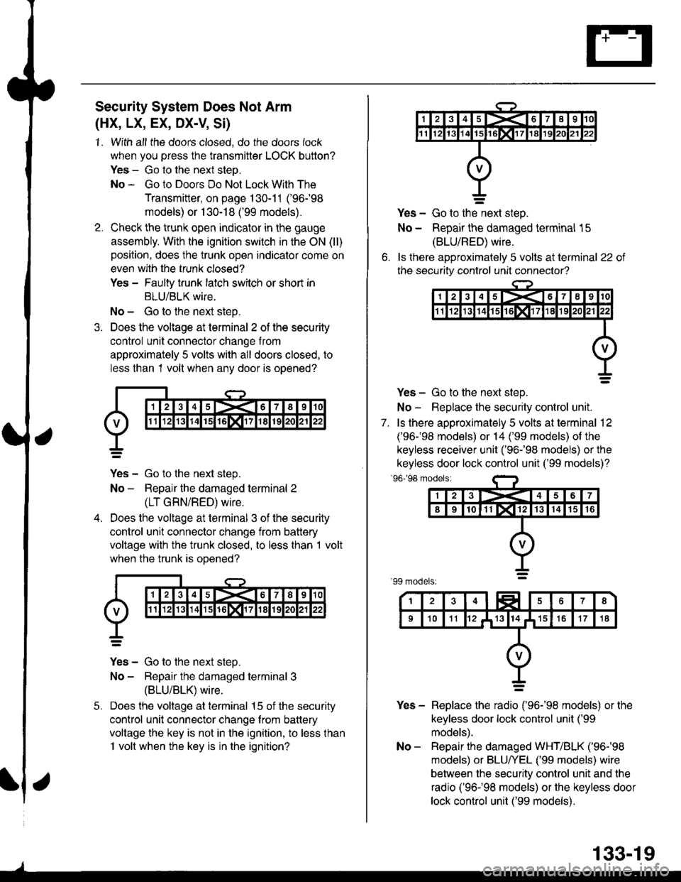
Security System Does Not Arm
(HX, LX, EX, DX-V, Si)
1. With all the doors closed, do the doors lock
when you press the transmitter LOCK button?
Yes - Go to the next steo.
No - Go to Doors Do Not Lock With The
Transmitter, on page 130-11 ('96-98
models) or 1 30-18 ('99 models).
Check the trunk open indicator in the gauge
assembly. With the ignition switch in the ON (ll)
position, does the trunk open indicator come on
even with the trunk closed?
Yes - Faulty trunk latch switch or shod in
BLU/BLK wire.
No - Go to the next steo.
Does the voltage at terminal 2 of the security
control unit connector change from
approximately 5 volts with all doors closed, to
less than 1 volt when any door is opened?
Yes - Go to the next step.
No - Repair the damaged terminal 2
(LT GRN/RED) wire.
Does the voltage at terminal 3 of the security
control unit connector change from battery
voltage with the trunk closed, to less than 1 volt
when the trunk is ooened?
Yes - Go to the next steo.
No - Repair the damaged terminal 3
{BLU/BLK) wire.
Does the voltage at terminal 15 of the security
control unit connector change from battery
voltage the key is not in the ignition, to less than
1 volt when the key is in the ignition?
5.
o.
Yes - Go to the-next step.
No - Repair the damaged terminal 15
(BLU/RED) wire.
ls ihere approximately 5 volts at terminal 22 of
the security control unit connector?
Yes - Go to the next step.
No - Replace the security control unit.
7. ls there approximately 5 volts at terminal 12
('96-'98 models) or 14 ('99 models) of the
keyless receiver unit ('96-�98 models) or the
keyless door lock control unit ('99 models)?'96198 modelsi
Yes - Replace the radio ('96-'98 models) or the
keyless door lock control unit ('99
models).
No - Repair the damaged WHT/BLK ('96-'98
models) or BLU/YEL ('99 models) wire
between the security control unit and the
radio ('96-�98 models) or the keyless door
lock control unit ('99 models).
133-19
Page 2065 of 2189
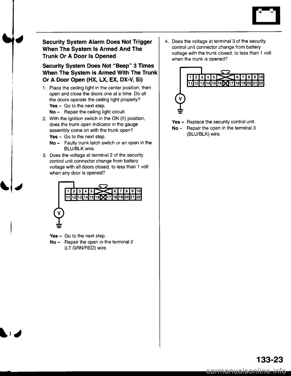
Security System Alarm Does Not Trigger
When The System ls Armed And The
Trunk Or A Door ls Opened
Security System Does Not "Be€p" 3 Times
When The System is Armed With The Trunk
Or A Door Open (HX, LX, EX, Dx-V SD
1. Place the ceiling light in the center position, then
open and close the doors one at a time. Do all
the doors operate the ceiling light properly?
Yes - Go to the next steo.
No - Repair the ceiling light circuit.
With the ignition switch in the ON (ll) position,
does the trunk open indicator in the gauge
assembly come on with the trunk open?
Yes - Go to the next step.
No - Faulty trunk latch switch or an open in the
BLU/BLK wire.
Does the voltage at terminal 2 of the security
control unit connector change trom battery
voltage with all doors closed, to less than I volt
when any door is opened?
Yes - Go to the next step.
No - Repair the open in the terminal 2
(LT GRN/RED) wire.
4. Does the voltage at terminal 3 of the security
control unit connector change from battery
voltage with the trunk closed, to less than 1 volt
when the trunk is opened?
Yes - Replace the security control unit.
No - ReDair the oDen in the terminal 3
(BLU/BLK) wire.
133-23