1998 HONDA CIVIC Engine block
[x] Cancel search: Engine blockPage 554 of 2189

\
\
(From page 11-284)
\(cont'd)
11-285
EVAP PURGE CONTROL SOI.INOID
VALVE 2P CONNECTOR IC114I
Wire side otfemaleterminals
?,
I,l,lil?"",,,u
EL,TWYEL)
Check the EVAP pirrge controlsolenoid valvei1. Disconnect the 2P connector
lrom the EVAP purge control
solenoid valve.
2. Ouickly raise the engine speed
to 3,000 rpm.
ls there vacuum?
InsDect vacuum ho56 routing.ll OK, replace the EVAP Purgecontrol solenoid valve.
Chock for a short in the wire(PCS linel:1. Turn the ignition switch OFF
2. Disconnect ECM/PCM connec'
tor A (32Pi.
3. Check for continuity between
the EVAP PUrge control sole
noid valve 2P connector termi
nal No.2 and body ground.
Check the vacuum when hot:
1. Turn the ignition switch OFF
2. Block the rear wheels and set
the parking brake.3. Jack up the front o{ the vehi-
cle and support it with safety
stands,4. Start the engine. Hold the
engine al 3,000 rpm wlth no
load (in Park or neutral) until
the radiator fan comes on, then
let it idle.5, Check for vacuum at the vac-
uum hose with transmissaonin gear (A/T in B Position,M/T in lst gear) after starting
the engrne.6. Ouickly raise the engine speed
to 3,000 rpm.
Reoair short in the wire botween
the EVAP purg€ cor|t]ol solenoid
valve and the ECM/pcM lA15l.ls there continuity?
Substitute a known-good ECM/
PCM and recheck. lf sYmPtom/indication goes eway. repl.c€ the
original ECM/PCM.
Check the EVAP Purg€ control
solenoid valve:1. Turn the ignition switch OFF
2. Disconnect the 2P connector
from the EVAP Purge control
solenoid valve and warm lt
up to normal operating tem_perature again if necessary
3. Stan the engine.4. At the harness side, measure
voltage between the EVAP
Purge control solenoid valve
2P connector terminal No. 1
and No. 2 with the transmission in gear (A,/T in E Posi-tion, M/T in 1st gear).
In3pect vacuum ho3€ touting.
ll OK, replace EVAP Purge con-
lrol aolenoid vtlv€.
Check lo. an open in the wire
llGl linel:At the harness side, measure volt
age between the EVAP Purge con-
trol solenoid valve 2P connectorterminal No. 1 and body groundRepeir open in tho wire between
EVAP purge conttol solenoid valv€
and the No. 15 ALTERNATOR SP
SENSOR (7.5 A fu3e
IBLK/YELI
lTo page 11 286i(To page 11-286)
Page 559 of 2189

Emission Control System
Ch€ck the EVAP purge controlsolenoid valv6:1. Disconnect the 2P connectorfrom the EVAP purge controlsolenoid valve.2. Ouickly raise the engine speedto 3,000 rpm.
Insped vacuum hose routing.lf OK. roplace the EVAP purge
control solonoid valve.
Chock tor r short in the wir€
{PCS line):1. Turn the ignition switch OFF.2. Disconnect ECM/PCM connec-tor A (32P).
3- Check tor continuity betweenthe EVAP purge control sole-noid valve 2P connector termi-nal No. 2 and body ground.
Check the vacuum when hot:1. Turn the ignition switch OFF.2. Block the rear wheels and setthe parking brake.3. Jack up the lront of the vehi-cle and support it with safetystands.4. Start the engine. Hold theengine at 3,000 rpm with noload (in Park or neutrali until
the radiator fan comes on, thenlet it idle.5. Check for vacuum at the vac-uum hose with transmissionin gear (A/T in E position,
lvl/T in 1st gear) after startingthe engine.6. Ouickly raise the engine speedto 3,000 rpm.
Rooair shoft in the wire belwegnthe EVAP pulg6 control solenoidvalvs and tho ECM/PCM {A61.ls there continuity?
Substitute a known-good ECM/PCM and rech6ck. lt 3ymptom/indicrtion 90e3 rway, r6plac6 th€o.iginal ECM/FCM.
Check th€ EVAP purge controlsolenoid valve:1. Turn the;gnition switch OFF.2. Disconnect the 2P connectorfrom the EVAP purge controlsolenoid valve and warm itup to normal operating tem-perature again if necessary.3. Start the engine.4- At the harness side, measurevoltage between the EVAPpurge control solenoid valve2P connector terminal No. 1and No.2 with the transmis-sion in gear {A/T in E posi-tion, M/T in lst geari.
In3pect vacuum hoae routing.lf OK, repl.ce EVAP purge con-trol solonoid valve.ls there battery voltage?
Chock for an open in the wire(lG1 lina):At the harnoss side, measure volt-age beNveen the EVAP purge con-trol solenoid valve 2P connectorterminal No. 1 and body ground.
Repair open in the wire b€lwe€nEVAP purge contrl 3olenoid valv6and lhe No. 15 ALTERNATOR SPSENSOR 17.5 A, fu3e.
ls there battery voltage?
Evaporative Emission (EVAPI Controls (cont'dl
(From page 11-289)
(To page 11-291)
11-290
IJ
EVAP PURGE CONTROL SOLENOIDVALVE 2P CONNECTOR IC114I
PCS
IRED/YEL)
temaletermrnars
of
PCS(RED/YEL)
tGlIBLK/YEL)
{To page 11 291)
Page 574 of 2189

Pressure Plate
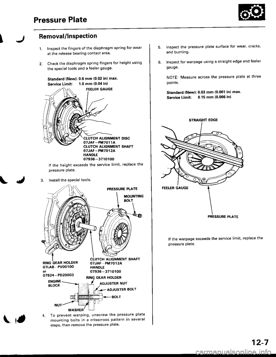
\Removal/lnsPection
1.Inspect the fingers of the diaphragm spring for wear
at the release bearing contact area.
Check the diaphragm spring fingers for height using
the special tools and a feeler gauge.
Standard {New}: 0.6 mm (0.02 inl max.
Seruice Limit: 1.0 mm {0.04 in}
FEELER GAUGE
CLUTCH ALIGNMENT DISCOTJAF_PM7O1 1ACLUTCH ALIGNMENT SHAFTOTJAF-PM7012AHANDLE07936-37tOtOO
lf the height exceeds the service limit, replace the
pressure Plate.
3. Installthe special tools
PRESSURE PLATE
MOUNTINGBOLT
ALIGNMENT SHAFTOTJAF-PM7012AHANDLE07936-371010Oo7924-PD20003GEAR HOLDER
07LA8-PVOOIOOot
ENGINEBLOCKADJUSTER BOLT
BOLT
4. To prevent warping, unscrew the pressure plate
mounting bolts in a crisscross pattern in several
steps, then remove the pressure plate.
f
12-7
lnspect the pressure plate surface for wear' cracks,
and burning.
Inspect for warpage using a straight edge and leeler
ga uge.
NOTEr Measure across the pressure plate at three
pornrs.
Standard (Newl: 0.03 mm (0.001 inl max.
Service Limit: 0.15 mm (0.006 inl
lf the warpage exceeds the service limit, replace the
pressure plate.
STBAIGHT EDGE
Page 604 of 2189

Countershaft Assembly
Reassembly (cont'd)
4. Suppon the countershaft on a steel block as shownand install 3rd gear using the special tools and apress.
PRESS
35 mm l.o.07746-0030400
5. Install 4th gear using the special tools and a press.
DRlvER. 40 mm
DRIVER, 40 mm LO.07746 -0030100
ATTACHMENT,
07746- 0030100
ATTACHMENT,
DRIVER, 40 mm l.D.07746-0030100
ATTACHMENT,30 mm l.D.
35 mm LO.07746-0030400
6. Install 5th gear using the special tools and a Dress.
07746-00303005TI{ GEAR
.g
7. Install the bearings in the direction shown using thesDecialtools and a oress.
CAUTION: Install ths bearings with a maximumpressure ot 7.8 kN {800 kgt, 5,786 lbfl.
ATTACHMENT,30 mm l.D.07745 - q'303tl)
*1: 016Y7 engine*2: D16Y5, D16Y8 enginesThin edge of outerrace faces down,
8. Securely clamp the countershaft assemblv in
bench vise with wood blocks.
LOCKNUT
108+0r108N.m(11.0 * 0 - 11.0 kgt m. 79.6 - 0 * 79.6 tbf.ft)
Install the spring washer, tighten the locknut, thenstake the locknut tab into groove.
/rt-\
srySnap ring
lacss up.
\J
Page 725 of 2189

FCM CONNECTOR D {16P)
\o
14-47
Terminal NumberSignalDo3criptionMeasuring Conditions/Torminal Vohage
D1LCALock-up control solenoid valve A
control
When lock-up is ON: Battery voltage
With no lock-up: 0 V
SHBShift control solenoid valve B
control
In E position, in 1st and 2nd gear in E, E
position: Battery voltage
ln 3rd gear in E, E, in 4th gear in E posi-
tion;0 V
D3LCBLock-up control solenoid valve B
control
When full lock-up: Battery voltage
With half lock-up: Pulsing signal
D4Not used
D5VB SOLLock-up control solenoids, shift
control solenoids and linear
solenoid power supply electrode
with ignition switch oN (ll): Battery voltage
With ignition switch OFF: 0 V
D6ATP RAy'T gear position switch
E position input
tnEposition:0V
In other than E position: Approx. 10 V
SHAShift control solenoid valve A
control
In E] position, in 2nd and 3rd gear in p!, [Q]
position: Battery voltage
In 1st gear in E, @ position, in 4th gear in El
Dosition: 0 V
D8ATP D3A/T gear position switch
E position input
In E position:0V
In otherthan @ position: Approx. 10 V
D9ATP D4Ay'T gear position switch
E position switch
In El position: 0 V
In other than E position: Approx. 5 V
D10NCCountershaft speed sensor signal
input
Depending on vehicle speed: Pulsing signal
When vehicle is stooped: 0 V
D11NMMainshaft speed sensor signal
Inpur
Depending on engine speed: Pulsing signal
When engine is stopped: 0 V
D't2NMSGMainshaft speed sensor ground
D13ATP NPAy'T gear position switch E and
E position input
InE and E positions: 0V
In other than E and E positions: Approx. 10 V
D14AfP 2Ay'T gear position switch
E position input
tnEposition;0V
In other than E position: Approx. 10 V
D16NCSGCountershaft speed sensor
ground
Page 790 of 2189

Symptom-to-Component Chart
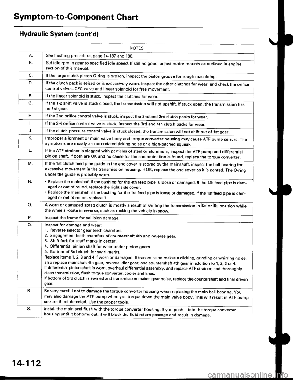
Hydraulic System (cont'dl
G.
n,
set idle rpm in gear to specified idle speed. lf still no good, adjust motor mounts as outlined in enginesection of this manual.
lf the clutch pack is seized or is excessively worn. inspect the other clutches for wear, and check the orificecontrol valves, CPC valve and linear solenoid for free movement.
lf the linear solenoid is stuck, inspect the clutches for wear.
lmproper alignment or main valve body and torque converter housing may cause ATF pump seizure. Thesymptoms are mostly an rpm-related ticking noise or a high-pitched squeak.
lf the l st clutch feed pipe guide in the end cover is scored by the mainshaft, inspect the ball bearing forexcessive movement in the transmission housing. lf oK, replace the end cover as it is dented. The o-rinounder the guide is probably worn.
Replace the mainshaft if the bushing for the 4th feed pipe is loose or damaged. lf the 4th feed pipe is danFaged or out of round, replace the right side cover.
Replace the mainshaft if the bushing for the 1st feed pipe is loose or damaged. lf the 1st feed pipe is darn-aged or out of round, replace it.
A worn or damaged sprag clutch is mostly a result of shifting the transmission inthe wheels rotate in reverse, such as rocking the vehicle in snow.
or E position while
Inspect for damage and wear:
1. Reverse selector gear teeth chamfers.
2. Engagement teeth chamfers of countershaft 4th and reverse gear.
3. Shift fork for scuff marks in center.
4. Differential pinion shaft for wear u nder pin ion gears.
5. Bottom of 3rd clutch for swirl marks.
Replace items 1,2,3 and 4 if worn or damaged. lf transmission makes a clicking, grinding orwhirring noise,also replace mainshaft 4th gear, reverse idler gear. and countershaft 4th gear in addition to 1, 2, 3 or 4.lf differential pinion shaft is worn, overhaul differential assembly, and replace ATF strainer, and thoroughlyclean transmission, flush torque converter, cooler and lines.lf bottom of 3rd clutch is swirled and transmission makes gear noise, replace the countershaft and final drivengear.
Be very careful not to damage the torque converter housing when replacing the main ball bearing, you
may also damage the ATF pump when you torque down the main valve body. This will result in ATF pumpseizure if not detected. Use the oroper roors.
Install the main seal flush with the torque converter housing. lf you push it into the torque converterhousing until it bottoms out, it will block the fluid return passage and result in damage.
See flushing procedure, page 14-187 and 188.
lf the large clutch piston O-ring is broken, inspect the piston groove for rough machining.
lf the l-2 shift valve is stuck closed, the transmission will not upshift. lf stuck open, the transmission hasno 1st gear.
lf the znd orifice control valve is stuck. inspect the 2nd and 3rd clutch oacks for wear.
lf the 3-4 orifice control valve is stuck, inspect the 3rd and 4th clutch oacks for wear.
lf the clutch pressure control valve is stuck closed, the transmission will not shift out of 1st gear.
lf the ATF strainer is clogged with particles of steel or aluminum, inspect the ATF pump and differentialpinion shaft. lf both are OK and no cause for the contamination is found, replace the torque converter.
Inspect the frame for collision damage.
14-112
Page 791 of 2189

Road Test
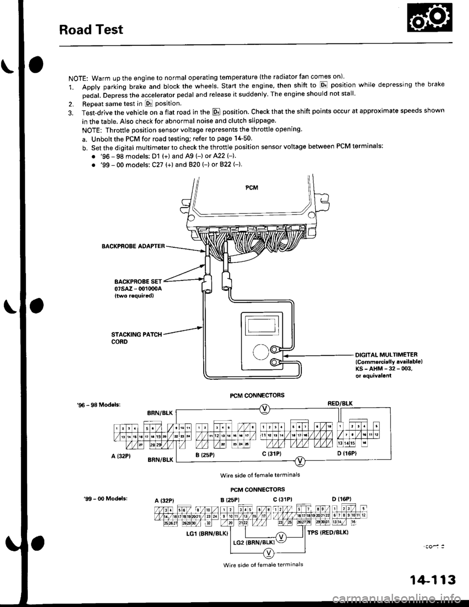
NOTE: Warm up the engine to normal operating tem peratu re (the rad iator fan comes on )'
1. Apply parking brake and block the wheels. Start the engine, then shift to E position while depressing the brake
Dedal, Depress the accelerator pedal and release it suddenly. The engine should not stall'
2. Repeat same test in E Position.
3. Test-drive the vehicle on a flat road in the E position. Check that the shift points occur at approximate speeds shown
in the table. Also check for abnormal noise and clutch slippage.
NOTE: Throttle position sensor voltage represents the throttle opening
a. Unbolt the PCM for road testing; refer to page 14-50.
b. Setthedigital multimeter to check the th rottle position sensor voltage between PCM terminals;
. '96 - 98 models: D1 {+) and A9 (-) or 422 (-}.
. '99 - 00 models: C27 (+) andB20t-) orB22{-}.
BACKPROBE ADAPTER
BACKPROBE SET07sAz - 001oq)A{two requiredl
DIGIIAL MULTIMETERlCommercially available)KS-AHM-32-003,or equivalenl
'96 - 98 Modelsr
Wire side ol temale terminals
PCM CONNECTORS
B t25Pl c (31P)
LG1 IBRN/BLK)
I (25P1c (31P}
A t32PtD (16P)
Wire side ol female terminals
'9!t - 00 Models:
1+113
Page 794 of 2189

Stall Speed
Test
CAUTION:
. To prev€nt transmission damage, do not t6st stall speed for more than ro sgconds at a time.. Do not shift the levor while raising the engine speed.. Bo sule lo remove the pressure gauge betoro testing stall speed.
'1. Engage the parking brake, and block the front wheels.
2. Connect a tachometer to the engine, and start the engine.
3. Make sure the Ay'C switch is OFF.
4. After the engine has warmed up to normal operating temperature (the radiator fan comes on). shift into E position.
5. Fully depress the brake pedal and accelerator for 6 to g seconds, and note engine speed.
6. Allow two minutes for cooling, then repeat the test in @ and @ positions.
NOTE:
. Stall speed tests should be used for diagnostic purposes only,. Stall speed should be the same in o., E and E positions.
Stall Spsed RPM:
Specification: 2.700 rpm
Service Limit: 2,550 - 2,850 rDm
TROUBLEPROBABLE CAUSE
. Low fluid level or ATF pump outDur. Clogged ATF strainer. Pressure regulator valve sluck closeo. Slipping clutch
. Slippage of 4th ctutch
. Slippage of 2nd clutch
. Slippage of lst clut"tr or. t"t g""io*-*"y "lut"h
Stall rpm high in D., E and E positions
Stall rpm high in El position
Stall rpm high in E posirion
Stall rpm high in E position
Stall rpm low in LDa . El and E positrons. Engine output low. Torque converter one-way clutch slipping
14-116