Page 1587 of 2189
-
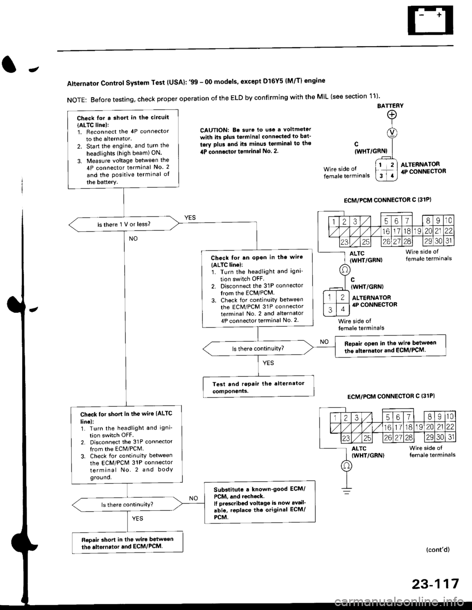
Alternator Control System Test {USA}: '99 - 0O models, except Dl6Y5 {M/T} engine
NOTE: Before testing, check proper operation ofthe ELD by confirming with the MIL (see section 11)'
BATTERY
CAUTION: Be sura lo use a voltmeter
with its plus te.minal conneqted io bat-
tery plus and it3 minus tgrminal to ths
4P connoctot tomrinal No. 2.
Wire side of
female terminals
c(WHT/GRNI
wire side offemale terminals
ALTERNATOR.P CONNECTOR
ECM/PCM CONNECTOR C 13lPI
ECM/PCM CONNECTOR C (31PI
(cont'd)
23-117
Check lor a sho.t in the circuit
{ALTC line):1, Beconnect the 4P connector
to the alternator.
2. Start the engine, and turn the
headlights (high beam) ON.
3. Measure voltage between the
4P connector terminal No. 2
and the Positive terminal of
the battery.
ls there 1 V or less?
Chcck for rn opon in the wire(ALTC lin6l:1. Turn the headlight and igni-
tion switch OFF
2. Disconnect the 31P connector
trom the ECM/PCM.
3. Check for continuity betlveen
the ECM/PCM 31P connectorterminal No. 2 and alternator
4P connector terminal No. 2
Repair opcn in the wire botweon
the alternstoi.nd ECM/PCM.ls there continuity?
Check tor short in the wire IALTC
line):1. Turn the headlight and igni-
tion switch OFF2. Disconnect the 31P connector
from the ECM/PCM.
3. Check for continuity between
the ECM/PCM 31P connector
terminal No. 2 and body
ground.
Substitute a known'good ECM/
PCM, and recheck.It prscribed voltagg is now avail'
abl€, replace tho original ECM/
PCM.
Raoair short in the wite between
the alle.nator and ECM/PCM,
1235618I10
/11611lo191 zo2122
23252621?82930JI
ALTC Wire side of(WHT/GRN) female terminals
o
Page 1708 of 2189
Moonroof
1.
Switch Test
Carefully remove the switch from the driver's dash-
board lower cover {see page 23-205}.
Check for continuitv between the terminals in each
switch position according to the table.
Terminal
t*',*-----__\I234
ut-t-
OPENo--o
CLOSEo---o
TILTo--o
23-234
Motor Test
'1.Remove the headliner (see section 20).
Disconnect the 2P connector from the moonroof
motor.
Terminal side of male terminals
Check the motor by connecting power and ground
according to the table.
4. lf the motor does not run, replace it (see section 20).
NOTE: See Closing Force Check in section 20 for
motor clutch test.
\_____lTr1
Position
,l
OPENo@
CLOSE@
Page 1709 of 2189
Open/Close-Tilt/Close Switch Test
1. Remove the headliner (see section 20).
2. Disconnect the 2P and 4P connectors from the moon-
roof motor and the switch.
3. Check for continuity between the terminals in each
switch position according to the table.
Terminal side of male terminals
Terminal
*r*"-
-\123
CLOSE .* TILTo--oo---o
CLOSE ..--. OPENo--o
4. lf there is no continuity, adiust or replace the switch'
l-t
23-239
Page 1717 of 2189
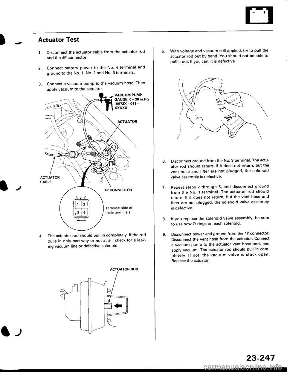
)Actuator Test
't.Disconnect the actuator cable from the actuator rod
and the 4P connector.
Connect battery power to the No 4 terminal and
ground to the No. 1, No. 2 and No. 3 terminals.
Connect a vacuum pump to the vacuum hose Then
apply vacuum to the actuator.
2.
VACUUM PUMPGAUGE,0 - 30 in.Hg.
{A973X - 041 -
xxxxxl
ACTUATOR
,lP CONNEcToR
Terminalside o{male termrnals
4. The actuator rod should pull in completely. lf the rod
pulls in only pan-way or not at all' check for a leak-
ing vacuum line or defective solenoid.
ACTUATOF ROD
l-t
23-247
5. With voltage and vacuum still applied, try to pull the
actuator rod out by hand. You should not be able to
oull it out. ll you can, it is defective
1.
Disconnect ground from the No.3 terminal. The actu-
ator rod should return lf it does not return, but the
vent hose and filter are not plugged, the solenoid
valve assembly is defective.
Repeat steps 2 through 5, and disconnect ground
from the No. 1 terminal. The actuator rod should
return. lI it does not return, but the vent hose and
filter are not plugged. the solenoid valve assembly
is defective.
It you replace the solenoid valve assembly, be sure
to use new O-rings on each solenoid.
Disconnect power and ground from the 4P connector.
Disconnect the vent hose from the actuator. Connect
a vacuum pump to the actuator vent hose port, and
apply vacuum. The actuator rod should pull in com-
pletely. lf not, the vacuum valve is stuck open.
Replace the actuator'
8.
Page 1756 of 2189
Troubleshooting
Diagnostic Trouble Code (DTCI Ghart -'96 - 97 Models (cont'd)
NOTE:* l: In case of an intermittent failure DTC g-1, it means there was an internal failure of the SRS unit or a faultv SRS indicator light circuit. Do the troubleshooting for intermittent failures (see page 24-15).*2: lt both DTC 9-2 and DTC 5-1 are indicated, do the troubleshooting for DTC g-2.*3: Apply to the '97 model coupe HX and DX.*4: DTC cannot be read with a Honda PGM Tester; check by jumping the SCS service connector.
24-18
.
Possiblg cause Cortestive action
5 3 I Internal failure of the SRS unitSRS unit
replacement
lnternal failure of the SRS unitSRS unit
replacement
Internal failure of the SRS unit
Internal failure of the SRS unitSRS unit
replacement
Internalfailure of the SRS unit ortwo failures at atime
8-6*3 Internalfailure ofthe SRS unit
Internal failure of the SRS unit
Faulty SRS power supply (VB line)
SRS unit replacement code (SRS unit must not
be used any longe.)
J
Page 1757 of 2189
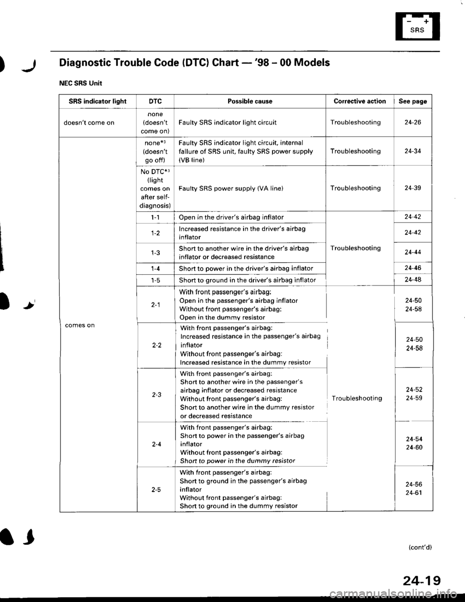
)Diagnostic Trouble Code (DTC) Chart -'98 - 00 Models
NEC SRS Unit
Ir
SRS indicator lightDTCPossible causeCorrestive actionSee page
doesn't come on
none
(doesn't
come on)
Faulty SRS indicator light circuitTroubleshooting24-26
comes on
none*3
(doesn't
go off)
Faulty SRS indicator light circuit, internal
fallure of SRS unit, faulty SRS power supply
(VB line)
Troubleshooting24-34
No DTC*3(lis ht
comes on
after self-
diagnosis)
Faulty SRS power supply (VA linelTroubleshooting24-39
l-1Open in the driver's airbag inflator
Troubleshooting
24 42
Increased resistance in the driver's airbag
inflator24-42
Short to another wire in the driver's airbag
inflator or decreased resistance24-44
't -4Short to power in the driver's airbag inflator24-46
t-5Short to ground in the driver's airbag inflator24-48
With front passenger's airbag:
Open in the passenger's airbag inflator
Without front passenger's airbag:
Open in the dummv resistor
24-50
24-54
With front passenger's airbag:
Increased resistance in the passenger's airbag
inflator
Without front passenger's airbag:
Increased resistance in the dummy resistor
24-50
24-58
with front passenger's airbag:
Short to another wire in the passenger's
airbag inflator or decreased resistance
Without front passenger's airbag:
Short to another wire in the dummy resistor
or decreased resistance
Troubleshooting
24-52
24,59
2-4
With front passenger's airbag:
Short to power in the passenger's airbag
inflator
Without front passenger's airbag:
Shon to power in the dummy resistor
24-54
24-60
With front passenger's airbag:
Short to ground in the passenger's airbag
inflator
Without front passenger's airbag:
Short to ground in the dummy resistor
24-56
24-61
(cont'd)
24-19
l,
Page 1758 of 2189
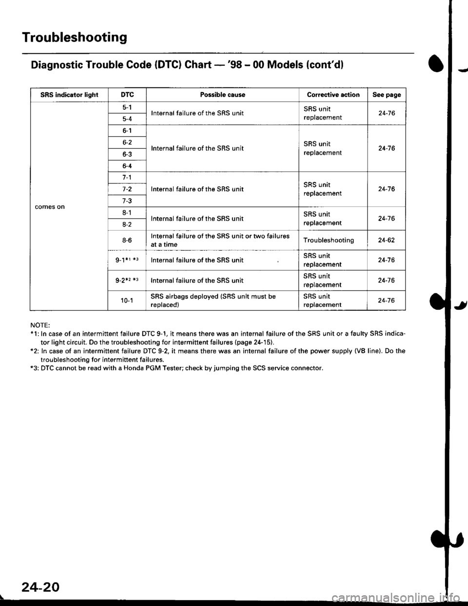
Troubleshooting
Diagnostic Trouble Code (DTC) Chart -'98 - 00 Models {cont'dl
NOTE:* 1: In case of an intermittent failure DTC 9-1, it means there was an internal failure of the SRS unit or a faulty SRS indica-
tor light circuit. Do the troubleshooting for intermittent failures (page 24-'15).*2: In case of an intermittent failure DTC 9-2, it means there was an internal failure of the power supply {VB line). Do the
troubleshooting for intermiftent failures.*3: DTC cannot be read with a Honda PGM Tester; check by jumping the SCS service connector.
24-20
\
SRS indicator lightDTCPossible causeCorrectiYe actionSee page
comes on
5-1lnternal failure of the SRS unitSRS unit
replacemenl24-765-4
6-1
lnternal failure of the SRS unitSRS unit
replacement24-7 66-2
o-5
6-4
7-1
lnternal failure of the SRS unitSRS unit
replacement24-76
7-3
8-1lnternal failure of the SRS unitSRS unit
reptacement24-7 68-2
8-6Internal failure of the SRS unit or two failures
at a trmeTroubleshooting24-62
g_1*r *3lnternal failure of the SRS unitSRS unit
replacement24-7 6
9-2+2 *3lnternal failure of the SRS unit5l|5 Untr
replacement24-76
10-1SRS airbags deployed (SRS unit must be
reDlaced)
SRS unit
replacement24-76
Page 1759 of 2189
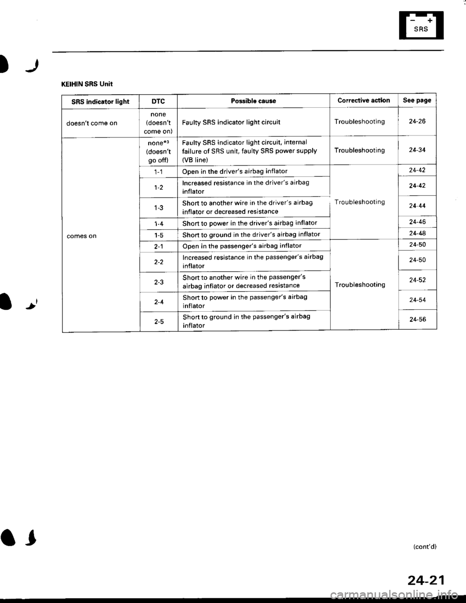
)r
l,.l
I
KEIHIN SRS Unit
SRS indicator lightDTCPossible cau3eCorrective astionSee page
doesn't come on
none
(doesn't
come on)
Faulty SRS indicator light circuitTroubleshooting24-26
comes on
none*3
(doesn't
go offl
Faulty sRs indicator light circuit, internal
failure of SRS unit, faulty SRS power supply
{VB line)
Troubleshooting24-34
Open in the driver's airbag inflator
Troubleshooting
24-42
1-2Increased resistance in the driver's airbag
inflator24-42
1-3Short to another wire in the driver's airbag
inflator or decreased resistance24-44
1-4Short to power in the driver's airbag inflator24-46
1-5Short to ground in the driver's airbag inflator24-44
2-1Open in the passenger's airbag inflator
Troubleshooting
24-50
Increased resistance in the passenger's airbag
inflator24-50
Short to another wire in the passenger's
airbag inflator or decreased resistance24-52
2-4Short to power in the passenger's airbag
inflator24-54
Short to ground in the passenger's airbag
inflator24-56
(cont'd)
24-21