1998 HONDA CIVIC brake line
[x] Cancel search: brake linePage 980 of 2189

ATF Filter
l.Removal/lnstallation
!@ Make sure lifts, lEcks, snd safoty stands
ara pl8ced properly {sae section 1).
CAUTION: While removing and installing the ATF tilier,
be sure not to allow dust or other for6ign particle3 to
enter thg transmission.
1. Raise the front of the vehicle, and support it with
safety stands (see section 1).
2. Set the parking brake, and block both rear wheels
securely.
3. Remove the drain plug, and drain the CVT fluid.
Reinstall the drain plug with a new sealing washer
{see page 14-299).
fl,
5.
CAUTION: Keep all toreign particles out ot the
transmission.
Remove the ATF cooler hoses at the ATF cooler
lines. Turn the ends of the ATF cooler hoses up to
prevent ATF from flowing out, then plug the ATF
cooler noses.
CAUTION: Keep all foreign particles out of the
transmission.
Remove the right front mounvbracket.
10 x 1.25 mm4{ N.m {i1.5 kgf.m,33 lbf ft)
ATF COOLER LINE
10 x 1.25 mm54 N.m {5.5 kgt'm,
40 rbl.ft)
ATF COOLER HOSE(|'t
14-303
6. Remove the ATF cooler outlet line.
7. Remove the ATF cooler line bracket bolt.
8. Remove the ATF pan (fourteen bolts)
9. Remove the ATF cooler inlet line from the ATF pan
(three bolts).
10. Remove the ATF filter, and clean it.
11. Check that the ATF filter is in good condition.
12. Replace the ATF filter if it is clogged.
LINE BOLT28 N.m {2.9 kgf.m,21 lbt.ft)
ATF COO1TR OUTIET
6x1.0mm
ATF COOLER INI-ETLINE ERACKET BOLT8 x 1.25 mm26 N.m (2.7 kgt.m,20 rbtftt
O.RINGReplace.
ATF
ATF FILTER
ATF PAN
6x1.0mm12 N.m (1.2 kgt'm,8.7 lbl'ft)
lnstall the ATF filter in the reverse order of the
removal procedure.
GAUTION: Keep all foreign particles out ot the
transmission,
NOTE:
Replace the O-rings, the ATF pan gasket and
sealing washers.
lf the ATF cooler inlet line bracket is bent or
warped. put it back to the original position
GASKETReplace.
'13.
12 N m (1.2 kgf m,
Page 990 of 2189

6) TRANSMISSION HOUSING GASKET Replace'
@ DOWEL PIN
@) ATF FEED PIPE
@ o-RING Replace.
60 o-RING Replace.
@) DRIVE PULLEY SPEED SENSOR
@ TRANSMISSION HANGER
@ SNAP RING
@ txaust Sxtfu, zs t 31 mm selective part
@ SALL BEARING
6J RING GEAR6D SNAP RING
@ aevense aRlxe rND PLATE Selective part
@ REVERSE BRAKE DISC
@ REVERSE BRAKE PLATE
@ DISC SPRING6} THNUST WASHER
@} finusr NeeoLr eelnNc
@ THRUST WASHER
@ GARRIER ASSEMBLY
@ THRUST WASHER
@ THRUST NEEDLE BEARING
@} SUN GEAR
@ SEALING RING REPIACE'
@ NEEDLE BEARING
@ INPUT SHAFT
@ NEEDLE BEARING
@ SEALING RING FEPIACE'
@ SEALING RING {RUBBERI Replace'
@ ATF FEED PIPE
O END COVER
O ATF FEED PIPE
O DOWEL PIN
@ O-RING Replace.G) FEED PIPE FLANGE
@ reeo ppe ruruce puru
O] ROLLERO IruTENMEDNTE XOUSING ASSEMBLY
ao corutnoL sxlrr lsseugLv
@ tnlrusmtsstottt ttoustt'tc
@ SHIFT CABLE BRACKET
c) BREATHER CAP
@ oll- SEAL Replace.
@ CONTROL LEVER
G LoCK WASHER Replace.(D secololaY ceaR SHAFT SPEED sENsoR
o) onvel put-uv sPEED SENSOR
@ O-RING Replace.(O SNAP RING6 rnmrsutsstoru xouslNc oRlvEN PULLEY
SHAFT ROLLER BEARING
@ END COVER GASKET REPIACE'
@ o-RING Replace
6o mnruulL vnLVe goDY LINE A
64 MANUAL VALVE BODY LINE B
@ O-RING Replace.
@ DETENT SPRING
O ATF FEED PIPE
@ O-RING Replace.
@ MANUAL VALVE EODY
@ DOWEL PIN
@ r'rllull valve goDY SEPARAToR PLATE
6D SNAP RING
@t roRwlno cturcx ASSEMBLY
@ o-RING Replace
@ SNAP RINGo3 spnlruc aetlrupn/RETURN SPRING ASSEMBLY
@ nevense ennr eBtottt
@ o-RING Feplace.
@ SNAP RING RE'AINER
@ ATF FEED PIPE
.1,
TOROUE SPECIFICATIONS
6x1.0mm
6x1.0mm
8 x 1.25 mm
8 x 1.25 mm
8 x 1.25 mm
12 N.m (1.2 kgf'm,8.7 lbf'ft)
14 N.m {1.4 kgf'm, 10 lbift)
37 N.m (3.8 kgf'm, 27 lbf'ft)
26 N.m (2.7 kgf'm,20 lbf'ft)
29 N.m (3.0 kgf'm, 22 lbf'ft)
6B
8B
8F
8G
14-313
rl,
Page 996 of 2189
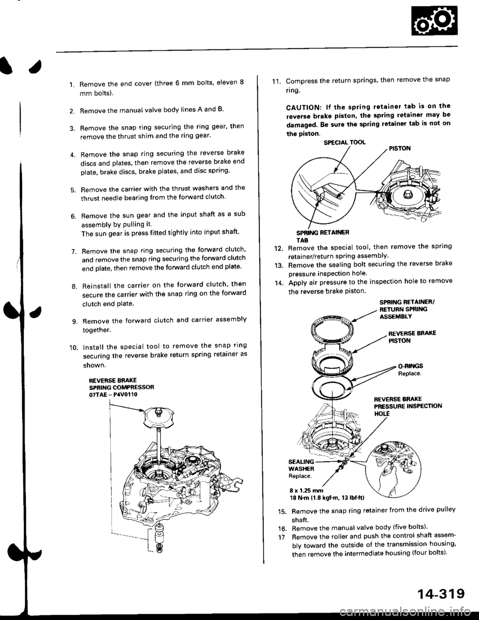
l.
1.
2.
Remove the end cover {three 6 mm bolts, eleven 8
mm bolts).
Remove the manualvalve body lines A and B
3. Remove the snap ring securing the ring gear, then
remove the thrust shim and the ring gear'
4. Remove the snap ring securing the reverse brake
discs and plates, then remove the reverse brake end
plate. brake discs, brake plates, and disc spring'
5. Remove the carrier with the thrust washers and the
thrust needle bearing from the forward clutch
6. Remove the sun gear and the input shaft as a sub
assembly bY Pulling it
The sun gear is press fitted tightly into input shaft'
7. Remove the snap ring securing the forward clutch,
and remove the snap ring securing the forward clutch
end plate, then remove the forward clutch end plate'
8. Reinstall the carrier on the forward clutch, then
secure the carrier with the snap ring on the forward
clutch end Plate.
9. Remove the forward clutch and carrier assembly
together.
'10. lnstall the special tool to remove the snap ring
securing the reverse brake return spring retainer as
snown.
REVERSE BBAKESPRING COMPRESSOR07TAE - PaV0110
11. Compress the return springs. then remove the snap
ring
CAUTION: lf the spring retainer tab is on the
rsverse braks piston, tho spting letainer may be
damaged. Be surs the spring letainer tab is not on
the piston.
SPfiING FETAIiGRTAB
Remove the special tool, then remove the spring
retainer/return spring assembly.
Remove the sealing bolt securing the reverse brake
pressure insPection hole.
Apply air pressure to the inspection hole to remove
the reverse brake Piston
12.
13.
14.
16.'t7
SPBING REYAINER/RETURiI SPRIiIGASSEMALY
REVERSE BNAXEPISTON
o-RrllcsReplace.
FCVERSE BRAKEPRESSURE INS?ECTK)NHOtl
SEALINGWASHERReplace.
8 x 1.25 mm18 N.m 11.8 kgf.m, 13 lbf.ttl
Remove the snap ring retainer from the drive pulley
shaft.
Remove the manual valve body (five bolts)'
Remove the roller and push the control shaft assem-
bly toward the outside of the transmission housing,
then remove the intermediate housing (four bolts)'
SPECIAL TOOL
14-319
Page 1014 of 2189
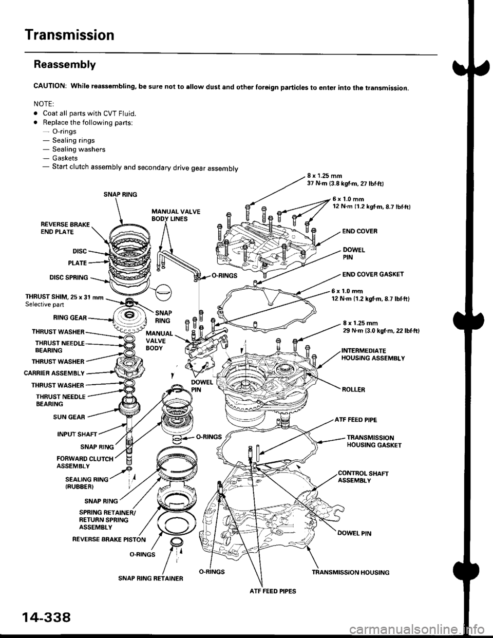
Transmission
Reassembly
CAUTION: While reassembling. be sure not to sllow dust and othor foreign particles to enter into the transmission.
NOTE:
. Coat all parts with CVT Fluid.
. Replace the following parts:- O-rings- Sealing rings- Sealing washers- Gaskets- Start clutch assembly and secondary drive gear assembly8 x 1.25 mm37 N.m {3.8 kgf.m,27 lbtftl
MANUAL VALVE
6x1.0mm12 N m 11.2 kgf.m,8.7 lbl.ft)
LINESREVERSE BRAKEEND PLATE
Dtsc
PLATE
DISC SPRING
THRUST WASHER
CARRIER ASSEMBLY
THRUST WASHER
THRUST NEEDLEBEARING
END COVEB
DOWELPIN
END COVER GASKET
6x1.0mm12 N.m 11.2 kgtm,8.7 lbtft)THRUST SHIM,25 x 31 mmSelective part
RING GEAR
THRUST WASHER
THRUSTBEARING
8 x 1.25 mm29 N.m 13.0 kgl m, 22 lbtftl
INTERMEDIATEHOUSING ASSEMBLY
ROLI.IR
SNAPRINGeBH^cMANUALVALVEBOOY
SUN GEAR
INPUT SHAFT
(RUBEERI
ATF FEED PIPE
O-RINGSTRANSMISSIONHOUSING GASKETSNAP RING
FORWARD CLUTCH
SNAP RING
SHAFTASSEMALY
DOWEL PtN
SPRING RETAINER/RETURN SPRINGASSEMBLY
REVERSE BRAKE PISTON
O.RINGS
SNAP RING
ATF FEED PIPES
14-338
SNAP RING RETAINERTRANSMISSION HOUSING
Page 1016 of 2189
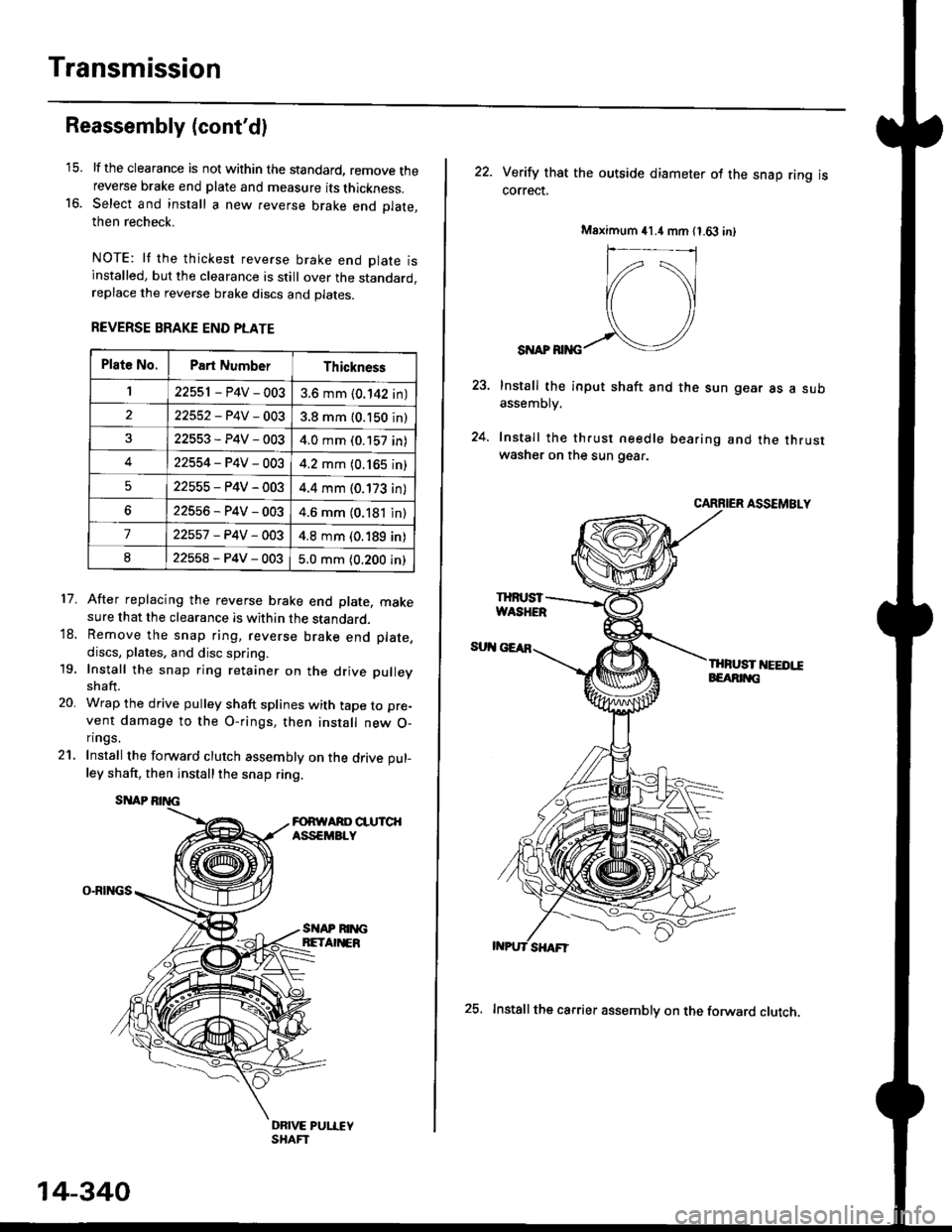
Transmission
16.
Reassembly (cont'dl
21.
17.
lf the clearance is not within the standard, remove thereverse brake end plate and measure its thickness.Select and install a new reverse brake end Dlate.then recheck.
NOTE: lf the thickest reverse brake end olate isinstalled, but the clearance is still over the standard,replace the reverse brake discs and plates.
REVERSE BRAKE END PLATE
After replacing the reverse brake end plate, makesure that the clearance is within the standard.Remove the snap ring, reverse brake end plate,
discs, plates. and disc spring.
Install the snap ring retainer on the drive pulley
shaft.
Wrap the drive pulley shaft splines with tape to pre-
vent damage to the O-rings, then install new O-n ngs.
Install the forward clutch assembly on the drive pul-
ley shaft, then installthe snap ring.
SITAP
O-RINGS
18.
19.
20.
SI{AP RIM;BETA EB
DRIVE PUI.IEYSHAFT
Plat6 No.Part NumberThickness
122551 - P4V - 0033.6 mm (0.142 in)
22552-P4V-0033.8 mm (0.150 in)
22553-P4V-0034.0 mm (0.157 in)
422554-P4V-0034.2 mm (0.165 in)
522555-P4V-0034.4 mm (0.173 in)
622556-P4V-0034.6 mm (0.181 in)
722557 -P4V -OO34.8 mm (0.189 in)
822558-P4V-0035.0 mm (0.200 in)
14-340
25. Installthe carrier assembly on the forward clutch.
22. Verity that the outside diameter ol the snap ring iscorrect.
SI{AP RIiIG
Install the input shaft and the sun gear as a subassemDry.
Install the th.ust needle bearing and the thrustwasher on the sun gear.
CARRIER ASSEMBLY
THFUST I'IEEDI!EEARIT{G
Msximum 41.4 mm 11.63 in)
IHruST
Page 1149 of 2189
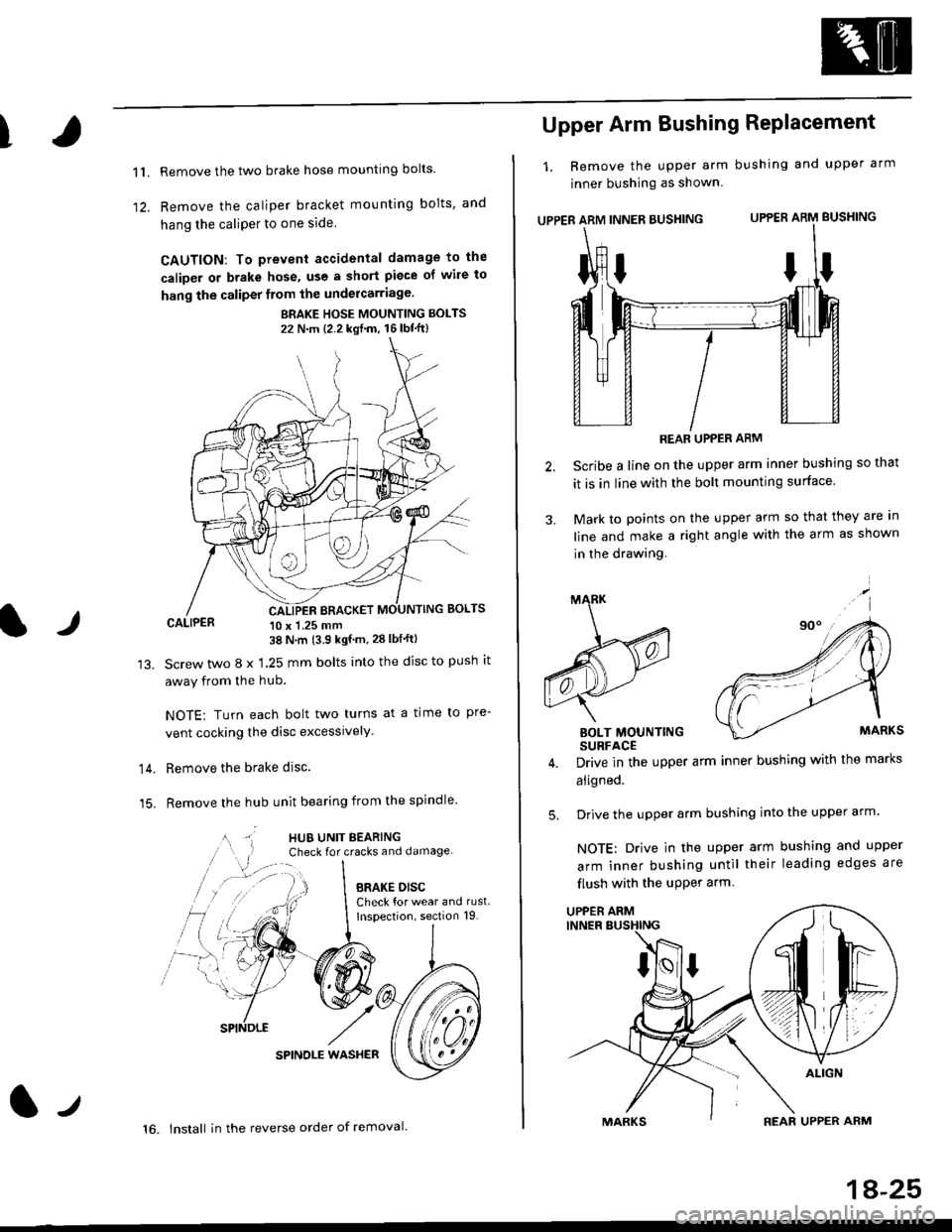
T
11.
1)
Remove the two brake hose mounting bolts
Remove the caliper b.acket mounting bolts, and
hang the caliPer to one side
CAUTION: To prevent accidental damage to the
caliper or brake hose, use a short piece of wile to
hang the caliper from the undercarriage.
BRAKE HOSE MOUNTING BOLTS
22 N'm {2.2 kgf'm, 16lbt"ft}
CALIPER 10 x 1.25 mm38 N'm (3.9 kgf'm, 28 lbf'ftl
Screw two 8 x 1.25 mm bolts into the disc to push it
away from the hub.
NOTE: Turn each bolt two turns at a time to pre-
vent cocking the disc excessively.
Remove the brake disc.
Remove the hub unit bearing from the spindle
SPINOLE WAS}IER
lr
14.
15.
lt
16. lnstall in the reverse order of removal.
1A-25
Upper Arm Bushing RePlacement
1. Remove the upper arm bushing and upper arm
jnner bushing as shown
UPPER ARM INNER BUSHING UPPER ARM BUSHING
REAR UPPER ARM
Scribe a line on the upper arm inner bushing so that
it is in line with the bolt mounting surface
Mark to points on the upper arm so that they are In
line and make a right angle with the arm as shown
in the drawing.
BOLT MOUNTINGSURFACE
Drive in the upper arm inner bushing with the marks
aligned.
Drive the upper arm bushing into the upper arm
NOTE: Drive in the upper arm bushing and upper
arm inner bushing until their leading edges are
flush with the uPPer arm
ttI
5.
UPPER ARM
Page 1155 of 2189
t
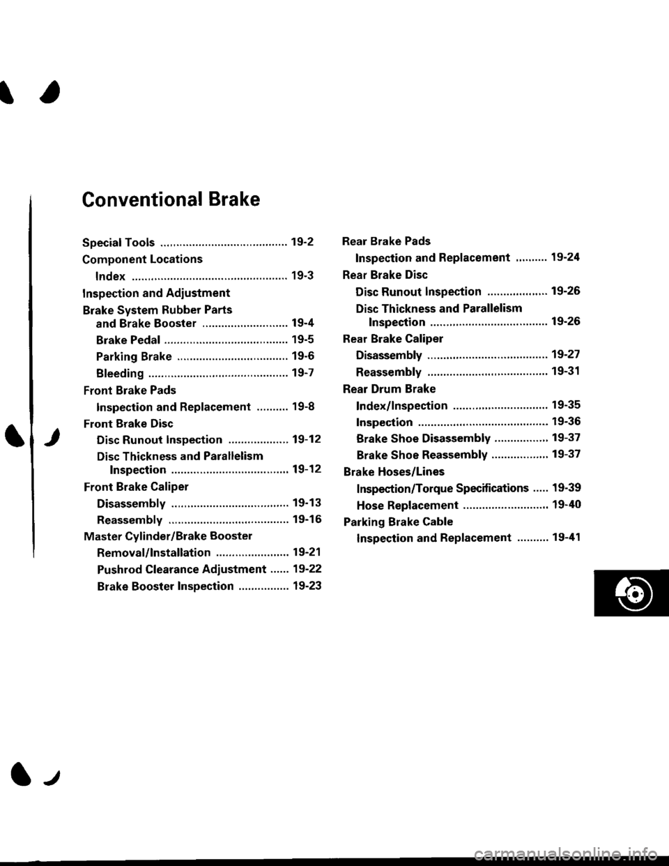
Conventional Brake
Speciaf Tools .............19'2
Component Locations
lndex ................ ...... 19-3
Inspection and Adiustment
Brake System Rubber Parts
and Brake Booster ...........,.,............. 19-4
Brake Pedal ............ 19-5
Parking Brake ........ 19-6
Bleeding ................. 19-7
Front Brake Pads
Inspection and Replacement .......... 19-8
Front Erake Disc
Disc Runout Inspection ................... 19-12
Disc Thickness and Parallelism
Inspection .......... 19-12
Front Brake Caliper
Disassembly .......... 19'13
Reassembly ........... 19-16
Master Cylinder/Brake Booster
Removal/lnstallation ....................... 19-21
Pushrod Clearance Adiustment ...... 19-22
Brake Booster Inspection ................ 19-23
Rear Brake Pads
Inspection and Replacement ,,........ 19-24
Rear Brake Disc
Disc Runout lnspection ................... 19-26
Disc Thickness and Parallelism
Inspection .......... 19-26
Rear Brake Caliper
Disassembly ...........19-27
Reassembly ........." 19-31
Rear Drum Brake
Index/lnspection .............................. 19-35
Inspection ....,.,....... 19-36
Brake Shoe Disassembly ..............." 19-37
Brake Shoe Reassembly ...............'.. 19-37
Brake Hoses/Lines
Inspection/Torque Specifications ..... 19-39
Hose Replacement ........................... 19-40
Parking Brake Cable
lnspection and Replacement ........,. 19-41
l-l
Page 1157 of 2189
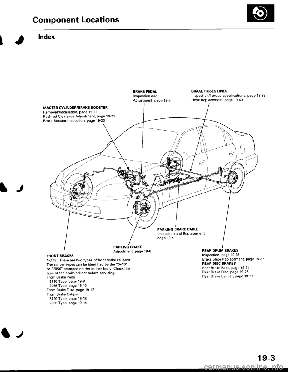
Component Locations
I
lndex
ERAKE PEDALInspectron andAdjustment, page 19 5
BRAKE HOSES LINESInspection/Torque specif ications, page 1 9-39Hose Replacement, page 19-40
MASTER CYLINDER/BRAKE BOOSTERRemoval/lnstallation, page 19 21Pushrod Clearance Adjustment, page 19_22
Brake Booster Inspection, page 19-23
lJ
PARKING BRAKE CASLEinspection and Replacement,page 19 41
FRONT BRAKESNOTE: There are two types offront brake calipers:The caliper types can be identitied by the "5410"
or "2056" stamped on the caliper body. Check thetype ot the brake caliper betore servicing.Front Brake Pads5410 Type: page 19-82056 Typer page 19 10Front Brake Disc, page 19-12Front Brake Caliper5410 Type: page 19-132056 Type: page 19-14
BBAKEAdiustment, page 19-6REAR ORUM BRAKESInspection, page 19-36
Brake Shoe Beplacement, page 19'37
REAR DISC BRAKESRear Brake Pads, page 19 24Rear Brake Disc, page 19 26Rear Brake Caliper, page 19'27
lJ
19-3