Page 163 of 2189

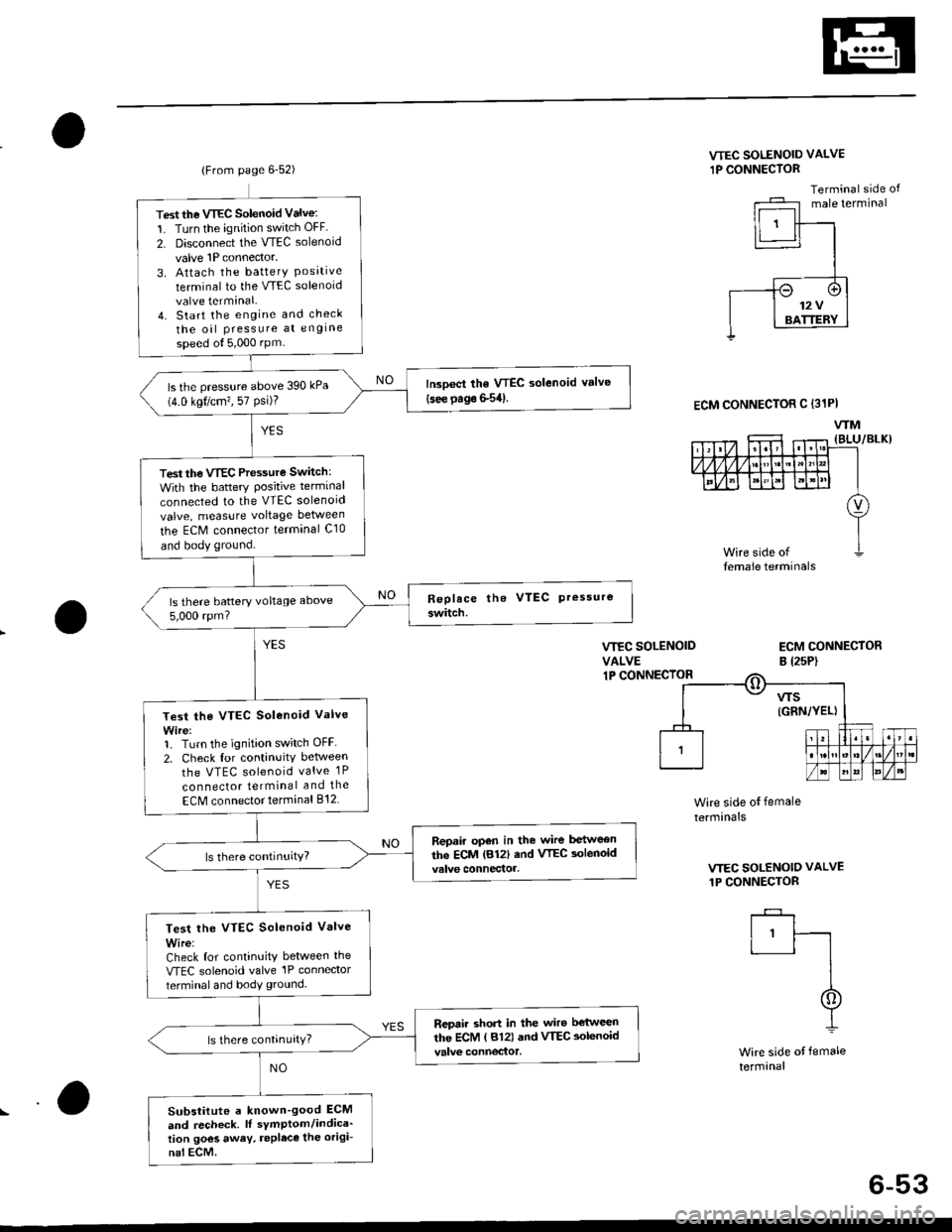
(From page 6-52)
Test the VTEC Solenoid Valve:
1. Turn the ignition switch OFF
2. Disconnect the VTEC solenoid
valve 1P connector,
3. Attach the batterY Posrtrveterminal to the VTEC solenoid
valve terminal.4. Start the engine and check
the oil Pressure at engine
speed ol5,000 rPm
lrcoect the VTEC solenoid valve(see page S54)ls the pressure above 390 kPa(4.0 kgt/cm?, 57 Psi)?
Test the VTEC Pressure Switch:
With the battery Positive terminal
connected to the VTEC solenoid
valve, measure voltage between
the ECM connector terminal C10
and body ground.
ls there battery voltage above
5,000 rpm?
Test the VTEC Solenoid Valve
Wire:1. Turn the ignition switch OFF
2. Check for continuitv between
the VTEC solenoid valve 1P
con nector terminal and the
ECM connector terminal 812
Repair open in the wire between
the ECM lB12| and VTEC aolenoid
Test lhe VTEC Solenoid Valve
Wire:Check for continuity between the
VTEC solenoid valve'lP connector
terminal and body ground.
Repair short in the wiro b€'tween
the ECM ( 812) and VTEC aolenoid
Substitute a known'good ECM
and recheck. lI sYmptom/indica'tion goes away. repleca the origi-
nal ECM.
VTEC SOLENOID VALVE
1P CONNECTOR
Terminal side ofmale terminal
VIEC SOLENOIDVALVE1P CONNECIOR
ECM CONNECTORB l2sP)
ECM CONNECTOR C (31PI
WM
Wire side ot female
termrnals
VTEC SOLENOID VALVE
1P CONNECTOR
I'ft
I
I
Wire side of female
termanal
6-53
Page 164 of 2189
VTEC Solenoid ValveVTEC Rocker Arms
a
I
(
Inspection
1. Remove the VTEC solenoid valve assembly fromthe cylinder head. and check the VTEC solenoidvalve filter for clogging.
. lf there is clogging, replace the engine oilfilter andengine oil.
6x1.0mm12 N.m (1.2 kgf.m, B,7 tbf.ftl
lf the filter is not clogged. push the VTEC solenoidvalve with your finger and check its movemenr.
. lf the VTEC solenoid valve is normal, check theengine oil pressure.
6x1.0mm12 N.m (1.2 kgtm,8.7 lbt.ft)
6-54
L-
SOLENOID
Manual Inspection
1. Set the No. 1 piston at TDC.
2. Remove the ignition wire cover and the wires.
3. Remove the ignition clamps while pulling up on theIock.
6xl.0mm9.8 N.m (1.0 kgl.m, 7.2 tbtftl
IGNITIONWIRE COVER
IGNITIONWIRE
\
LOCK
Page 166 of 2189
VTEC Rocker Arms
4.
Inspection Using Special Tools (cont,dl
Loosen the valve on the regulator and apply thespecified air pressure.
Specified Air Pressuro:
250 kPa {2.5 kgtlcm,, 36 psil- 490 kPa {5.0 kgtcm,, 7t psil
Make sure that the primary and secondary rockerarms are mechanically connected by the pistonsand that the mid rocker arms do no. move wnenpushed manually.
SECONDARYROCKER ARM
. lf any mid rocker arm moves independently ofthe primary and secondary rocker arms, replacethe rocker arms as a set.
Remove the tools.
Check the operation of the lost motion assembly bypushing on the mid rocker arm. The lost motionassembly should compress fully and operatesmoothly through its full stroke. Replace the assem_bly if it does not work smoothly.
After inspection. check that the Malfunction Indi_cator Lamp {MlL) does not come on.
7.
6-56
I
ll
;l
Page 179 of 2189
WATER BYPASS
HOSE
14. Remove the upper radiator hose, heater hose and
water bvpass hose.
HEATER
Remove the engine wire harness connectors and wlre
harness clamps from the cylinder head and the intake
manifold.
Four fuel injector connector
Engine coolant temperature (ECT) sensor connec-
tor
ECT gauge sending unit connector
ECT switch connector
ldle air control (lAC) valve connector
Manifold absolute pressure (MAP) sensor connec-
tor
Throttle position sensor connector
Primary Heated oxygen sensor (Primary HO2S)
connecror
VTEC solenoid valve connector
15.
a
a
a
a
a
\
16.
17.
Remove the spark plug caps and distributor form
the cylinder head.
Remove the upper bracket.
NOTE:
. Use a jack to support the engine before removing
the upp€r bracket is removed.
. Place a cushion between the oil panandthejack.
12 x 1.25 fin74 N.m 17.5 kgtm,
UPPER BRACKET
18. Remove the cylinder head cover.
{cont'd)
6-69
Page 181 of 2189
Rocker Arms
Removal
'1. Hold the rocker arms together with a rubber band to
prevent them from separating.
Remove the intake and exhaust rocker shaft oil con-
trol orifices, then remove the VTEC solenoid valve
and the sealing bolts.
NOTE: The shapes ofthe intake and exhaust oil con-
trol orifices are different, ldentify the parts as they
are removed to ensure reinstallation in the original
locauons.
2.
EXHAUST ROCKERSHAFT ORIFICE
INTAKE ROCKERORIFIGEClean.Clean.
O.RINGO.RINGReplace.
RUEBER BAND
Replace. _ (lX
-dJ'v-l-
\
6-71
3. Screw 12 mm bolts into the rocker arm shafts.
Remove each rocker arm set while slowly pulling
out the intake and exhaust rocker arm shafts.
12 mm BOLTS
ROCKER ARM SHAFTS
Page 309 of 2189
System Description
Electrical Connections ('99 - 00 Models except Dl6Y5 engine with M/Tl
(cont'd)
T:I
1
0
EVAP PURGE CONTROLSoLENOtOVAIVEc26 ECTECTSENSOR
D
EVAP COI{TROL CANISIE R
IATSENSOR
ta-t
c25 tAT
HO2S(sENSoFt
EVAP BYPASS SOI.ENOID VALVE
cl Po2s{tc"Eso! 87
)wEGF coNTRoL solENoro vaLvE'"c16PHO2S
vlsBr2VTEC SOLEr{O|D VATVE
H02SiSENSOR 2),wA23 SHO2S
VTECPFESSUFESWITCH
sEt{soR
-t,.1 f
I
BRAKE SWITCH
c7 sG1
SENSOB(Buln l oF
@E
lfil
*_r
/V | GAUGE
* lassEMBLIIl-
SPEEOSENSOR
tr
D5VBSOLo4tND A14
N DTI
NC DTOSPEEDSENSOR
LS+ Bl7UNEAR SOLENOID VALVET'I AT?04LS- a3
LOCIPr. l03alP03LCA 01P CONTBOISOIENOiDVALVE BLCB 03IOI{IROL SOLENOID VAIV€ A
SHIFI COTITROL SOLENOID VALVE BSHE D2
POStTtON
t----
I
To IIIT!FLOCK CONTROL UNIT
--t
L
l-
I
I
11-40
-.._.._.._.._l
,'-J
Page 313 of 2189
System Description
Electrical Gonnections ('99 - 00 Models except Dl6yS engine with M/T)(cont'd)
cad__J
neozvef- -l
q30
1""
h/wFDlt+l-lvss
EVAP CONTROLCANISTEF VENTSHUI VALVE
l,,"
I
Fl
TI
| "u,LB|.X'--Jf-ll
PsP swrcH'
VTECsoLEt{otoVALVE
cliaBLTC.YEL ----J----]
neo,"yrr.'--{l- ---5 |EVAP PUBGECONTROLSOLENOIDVALVE
clat
11-44
Page 357 of 2189

Troubleshooting
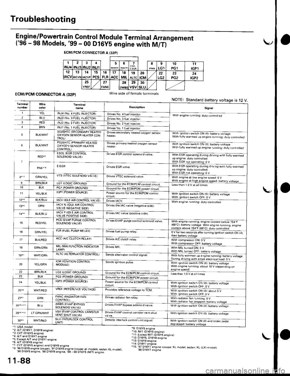
E n gine/P_o,weft ra in Control Module Term inal Arra n gement('96 - 98 Models, '99 - 00 Dl6yS engine with M/T)
-
ECM/PCM CONNECTOR A I32PI
1INJ62INJ3INJ21
INJl567I
LG110PGll1
IGPl12
ACV
131115
PCS
16
FLR17acc18MIL19ALTC20
tcM22PG221IGP2272A25
VSV30
SLU
ECM/PCM CONNECTOR A (32P)
'2: A./T (D16Y7, 016Y8 engine)13: CvT (D16Y5 enoin€)',4: A/T and D16y7 engine*5: Except A/T and D16Y7 €nsine'6r A/T (D16Y8 ensine)'7 Cw 1D16Y5 eng,nel and D16y8 ensrne'"'3:Bi..I?'Jt;".'e'.!ti.?i?l'""."T8"_";btfr
"fl
1-88
Wire side of female terminals
NOTE:Standard battery voltage12ts
'10i i,4/T (D16V5 engine)r11 Ex.ept M/l (D16V5 enqinelr12: 016Y5, D16YB enqine
r15:'97 016Y7 engine lcoupe: KL modet, sedan: KL (LXl modet),'98 D16Y7 engine
1
1
Sign.l
YELlNJ4 (No.4 FUEL INJECIOB)D ves No 4 ruel injector.Wilh engine runninq: ddly coniroted2BLUlNJ3 lNo. 3 FUEL TNJECTOBJDrives No. 3 lue Inteclor.38EDINJ2 (NO, 2 FUEI INJECTON)Drives No. 2 iuel njector.88NlNJl (No. 1 FUEL INJECTOB)Dives No. 1 ruelinjector.
5SO2SIITC (SECONDAFY HEATEDOXYGEN SENSOF HEATEF CONTFOL)
Orives secondary heated oxyqen sensorWith ignilion switch ON (lll: batery vo lageWith f!llywarmed up engine runninq:dLtv controled
6BLXAVHTPO2SHTC (PRIMAFY HEATEOOXYGEN SENSOR HEATERCONTROL)
Drives prihary healed oxygen sensorWith ignition switch ON ltt):baneryvottasewlhrdllywdrmedupcngne,Lnnrrq dury,orl.otred
FED{ESOL (EGF CONTRO!SOIENOIO VALVE)Drives EGF conlrolsoleno d vatve.Wilh EGR operating during drving wiih fu|y warmedup engrne: duty controttedWilh EGF nol opefating:O VE.EGRWith EGF operating du.ing driv og wilh iuty warmedup en9ine: dutycont.olted.With EGR not ooeralino; o V8*r/GFN/YELWS (VTEC SOLENOTD VALVE)Drives VTEC solenoid va veWilh eng ne at ow engine speed:O VWirh engine at h gh enqine speedr banery vohaae9BflN/BLKLG1 (LOGIC GROUND)Gro!nd lorthe €CM/PCM conlrotc rcuit.Lesslhan 1.0 V at a ttimest0ALKPG1 IPOWEF GFOUND)Ground ior rhe ECM/PCM power.tcuf.11YEVBLKIGPT iPOWEF SOUFCE)Power source forthe Ec[,l/PcM conlroWilh ignition swirch ON (tt): battery voltageWith gntron switch OFF: 0 VBLVBLUIACV (IDLE AIN CONTROL VALVE)Wilh engine r!nn ng: dlty contro ed13,.o8NIACV N lIDLE AI8 CONTFOLVALVE NEGATIVE SIOE)Drivesthe IAC valve {negalive side).
BLVBLUIACV P (IDLE AI8 CQNTROLVALVE POSITIVE SIDE)Orives IAC vaive (posilive side).
FEO/YELPCS (EVAP PURGE CONTFOTSOIENOIOVALVE)Drives EVAP pu.ge controtsolenoid vatve.Wilh engioe running, engin€ cootani betow 154,F'68'Cr bancry vohaSe w'ln ens nc runn,.o. eng,rc
GRN/YELFL8 (FUEL PU[4P FELAY)Orives fuelpump relay.0 V {or two secor os ahe' tJ n ng 'onir or \wnch ON ,,,,,
I7BLI(REOACC (A,/C CLUTCH RELAY)Drives A/C clutch relay.Wirh compressor ONr0 VWilh compressof OFF:banery votrage18GFN/ONNMIL (I\,lALFUNCTION INDICATOFWith MIL lLrned ON: 0 VWith illl turned OFF: banery volaqe19',AITC {AITERNAIOR CONIROL)se.ds ahernator controt signat.Wirh fully warmed.up engine ru.ntng: battery votlas€During drivins wnh smatl eteclricat toad: O V
20YEVGRNICM (IGNI'TION CONTROLMOOU!E)with ignltlon swilch ON (tl):b6n€ry vohageWilh ensine runnins: aboul t0 V (depending on
22BRN/BLKLG2 (LOGIC GAOUND)Ground for the ECM,/PCM conrrot ci'cu LLess than 1.0 V at a tt mes23BLKPG2 iPOWEA GROUND)Gro!nd lor the ECM/PCM power circuir.24YEUBLKlGP2 (POW€R SOUSCE)Power sou.ce lor the ECM/PCl, conrrolWnh ignilion swilch ON {it):battery vohageWilh ignilion switch OFF:0 V25*6WHT/FEDVSEF IREFEfl ENCE VOLTAGE)Provrdes reference voIaOe to TCM.With ignition switch ON (tt):abour 5 VWth gnition swltch OFF: O V21'1GFNFANC {RAOIATOR FANCONTFOL)Drives radialof fan ielay.With radialor fan f!nn nqr O VWilh radiato.tan stopped: batteryBL!2WBS (EVAP BYPASSSOLENOIO VALVE]Orives EVAP bypass sotenotd va !e.With ignirion swrrch ON (tt):barery vo rase
LT GRNA/VHTVSV (EVAP CONTFOTCANISTEFVENT SHUT VAIVE)Drives EVAP conlfot canisrer venl shulwnh ignirion sw'tch ON lr|l barery volaqe
WHT/NEDSLU (INTEFLOCK CONTFOLUNIT)Detects intenock conlrotLn t signalWhh ignition switch ON (tt)and brake pedadepf essed: battery vollage