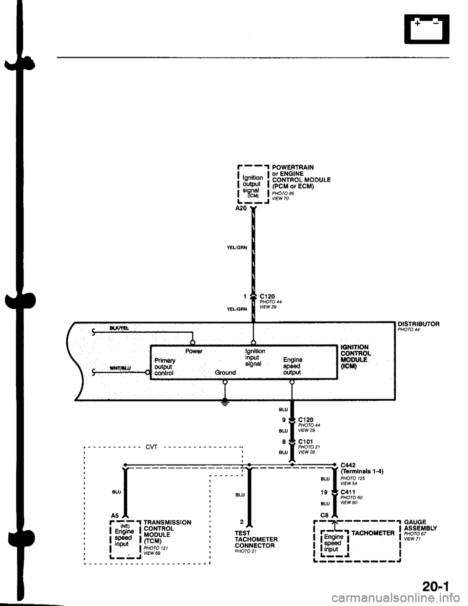
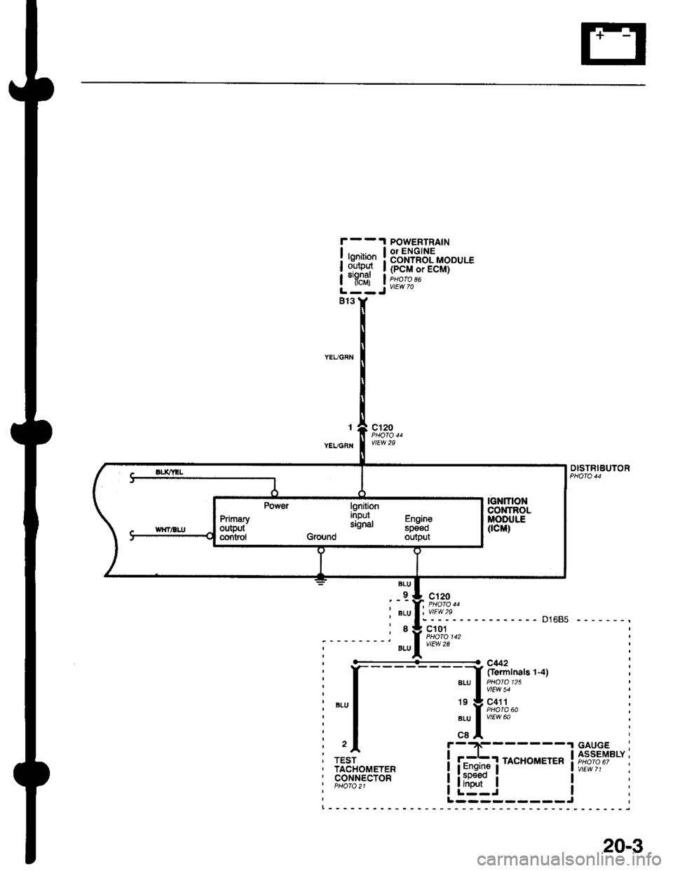
1998 HONDA CIVIC Tacho
[x] Cancel search: TachoPage 1817 of 2189

Contents
How to Use This Manual ICircuit Schematics (see Circuit Index)Fuse/Relaylnformation 6Ground-to-Componentslndex 6-6ComponentLocationPhotooraohs 201Conriector Views 202
Circuit Index
Accessory power socket 155Air conditionerAir delivery'96198 models 61'99-'00 models 61-2Blower controls'96198 models 60'99100 models 60-1Compressor controls 62Fans 63Anti-lock brake system (ABS) 44A/T gear position indicatorCVT 89All except CVT 89-1Automatic transmission controlsAll '96-'98 models except CVT and GX 39All '99100 models except CVT 39-8All GX models 39-8'96-'�98 CVT 39-4'99100 cw 39-12Back-up lightsCoupe and Sedan 110Hatchback l'10-1Brake lightsAll Coupes and'96-'98 Sedans 110-15'99-'00 Sedans 110-16Hatchback 110-17Brake system indicator light'96198 models 7'1'99100 models 71-1Ceiling light 114-3Charging system 22Condenser fan 63Console lights 114Cruise control 34Dash lights 114Daytime running lights 110- 13Engine coolant temperature gauge 81-1Fog lights 110-10Front parking lights 110-2Fuel gauge 81-1Fuse/relay boxUnder-dash 6Under-hood 6-4Underhood ABS 6-3Gauges 81Ground distribution 14Ground-to-Componentslndex 6-6Hazard warning lightsAll except '99100 Sedans 110-6'99100 Sedans 110-8Headlights 110-12Headlight switch 100Heater - See Air ConditionerHorn'96197 models 40'98 model 40-1'99100 models 40-2lgnition key reminder 73lgnition systemAll '96198 models except Dl685 20All '99100 models except D16Y5 with Mn 2O-2All D1685 engines 20-2'99-'00 D 16Y5 with M/T 20
lndicators 80Integrated control unit 70lnterlock systemAll except'96J98 CVT 138'96198CVT 138-1License plate lightsAll Coupes and '96-'98 Sedans I l0-3'99100 Sedans 1 10-4Hatchback 110-5Low fuel indicator light 74Moonrool'96197 models |22'98-'00 models 122-1Odometer 81Oil pressure indicator light 80-3Power distributionBattery to ignition switch, fuses, and relaysFuses to relays and components 10-2Power door locksAll models without keyless entry 130'96-'98 models with keyless entry 130-2'99100 models with keyless entry 130-12Power mirrorsWithout detogger 141With defogger '141-2
Power windows 120Programmed fuel injection system (PGNr-Fl)All '96-98 models except D1685 23All '99-'00 models except D16Y5with M/T and D1685 24All D1685 engines 25'99100 D16Y5 with M/T 23Radiator fan 63Rear window defogger'96-,98 models 64'99100 models 64-1Seat belt reminder 73Security system'96.'98 USA HX, LX, EX 133'96-'98 Canada EX, Si 133'99TOO USA HX, LX, EX, DX.V Si 133-4'99100 Canada EX, Si 133-4All CX and DX models 133-8Speedometer 81Starting systemA./T (All except Dl685) 21A"/r (D16Bs) 21-1Manualtransmission 21-2Slereo sound system 150Supplemental rastraint system (SRS) 47Tachometer 81TailliqhtsAllboupes and'96-'98 Sedans 110-3'99100 Sedans 1 10-4Hatchback 110-5Trunk light 114-3Turn signal lightsAll except'99100 Sedans 110-6'99-'00 Sedans 1 10-8Vehicle speed sensor (VSS) 33Wiper/washerFront 91Rear 92
10
Page 1872 of 2189

, r -.-- .l TBANSMTSS|ON
I igF"
POWEBTRAINor ENGINECONTROL MODULE(PCM or ECM)
vtEw 70
lgnitionoulputsignatflcM)
I
YEUGBN
c'120
vtEw 29
DISTRIBUTOR
D1685 -------,
BLU
_9-
BLU
8
9LU
:'!'\?- - -
c101
vtEw 2a
----------<- c442
I frerminals 1-4]a|-u a olo'25 |I vlEw 54
19 g C411a PHOTA 60aru I vtrw ool,cBA- -.t GAUGF
i f#f rAcHoirErER ift?i,?""i
liitr" i !I L--J IL ---- - --- -J
TESTTACHOMETERcor.rNEcToRPHO|O2l
lgniiionnrpur Fh^ih-signal "p_il;Ground output
PrimaryoutPutcontsol
20-3
Page 1980 of 2189

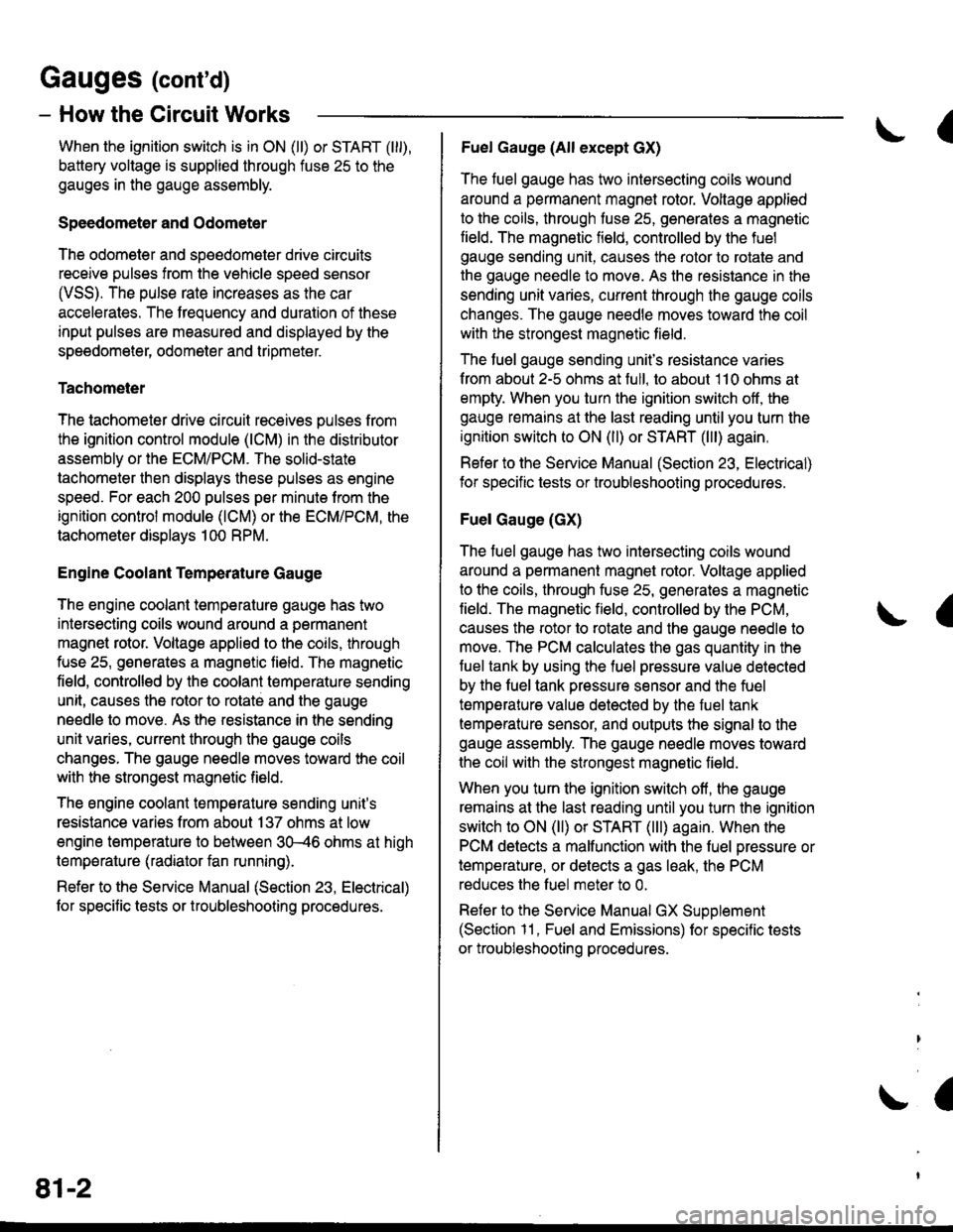
Gauges (cont'd)
- How the Gircuit Works
When the ignition switch is in ON (ll) or START (lll),
battery voltage is supplied through fuse 25 to the
gauges in the gauge assembly.
Speedometer and Odometer
The odometer and soeedometer drive circuits
receive pulses from the vehicle speed sensor
(VSS). The pulse rate increases as the car
accelerates. The frequency and duration of these
input pulses are measured and displayed by the
speedometer, odometer and tripmeter.
Tachometer
The tachometer drive circuit receives pulses from
the ignition control module (lCM) in the distributor
assembly or the ECM/PCM. The solid-state
lachometer then displays these pulses as engine
speed. For each 200 pulses per minute from the
ignition control modul€ (lCM) or the ECM/PCM, the
tachometer displays 100 RPM.
Engine Coolant Temperature Gauge
The engine coolant temperature gauge has two
intersecting coils wound around a permanent
magnet rotor. Voltage applied to the coils, through
fuse 25, generates a magnetic lield. The magnetic
field, controlled by the coolant temperature sending
unit, causes the rotor to rotate and the gauge
needle to move. As the resistance in the sending
unit varies, current through the gauge coils
changes. The gauge needle moves toward the coil
with the strongest magnetic field.
The 6ngine coolant temperature sending unit's
resistance varies from about 137 ohms at low
engine temperature to between 3H6 ohms at high
temperature (radiator fan running).
Refer to the Service Manual (Section 23, Electrical)
for specific tests or troubleshooting procedures.
81-2
(
Fuel Gauge (All except cX)
The fuel gauge has two intersecting coils wound
around a permanent magnet rotor. Voltage applied
to the coils, through tuse 25, generates a magnetic
field. The magnetic field, controlled by the fuel
gauge sending unit, causes the rotor to rotate and
the gauge needle to move. As the resislance in the
sending unit varies, current through the gauge coils
changes. The gauge needle moves toward the coil
with the strongest magnetic field.
The fuel gauge sending unit's resistance varies
from about 2-5 ohms at full, to about 110 ohms at
empty. When you turn the ignition switch off, the
gauge remains at the last reading until you turn the
ignition switch to ON (ll) or START (lll) again,
Refer to the Service Manual (Section 23, Electrical)
for specific tests or troubleshooting procedures.
Fuel Gauge (GX)
The fuel gauge has two intersecting coils wound
around a permanent magnet rotor. Voltage applied
to the coils, through fuse 25, generates a magnetic
field. The magnetic field, controlled by the PCM,
causes the rotor to rotate and the gauge needle to
move. The PCM calculates the gas quantity in the
fuel tank by using the fuel pressure value detected
by the tuel tank pressure sensor and the fuel
temperature value detected by the fuel tank
temperalure sensor, and outputs the signal to the
gauge assembly. The gauge needle moves toward
the coil with the strongest magnetic field.
When you turn the ignition switch off , the gauge
remains at the last reading until you turn the ignition
switch to ON (ll) or START (lll) again. When the
PCM detects a malfunction with the fuel pressure or
temperature, or detects a gas leak, the PCM
reduces the fuel meter to 0.
Refer to the Service Manual GX Supplement
(Section 11 , Fuel and Emissions) for specific tests
or troubleshooting procedures.
a
a
Page 2159 of 2189

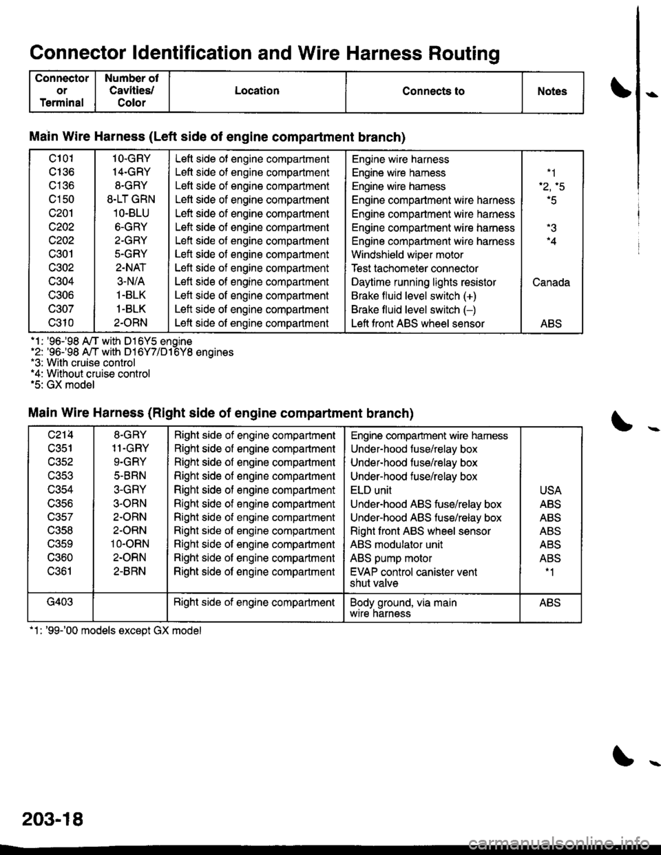
Connector ldentification and Wire Harness Routino
Connector
or
Terminal
Number ot
Cavities/
Color
LocationConnects toNotes
Main Wire Harness (Left side of engine compartment branch)
c101
cI36
c136
c150
c201
c202
c202
c301
c302
c304
UOUO
c307
c310
1O.GRY
14-GRY
8.GRY
8.LT GRN
1O-BLU
6.GRY
2-GRY
5.GRY
2.NAT
3-N/A
1.BLK
1-BLK
2.ORN
Left side ot engine compartment
Left side of engine compartment
Letl side of engine compartment
Lett side of engine compaftment
Left side of engine compartment
Left side of engine compartment
Left side of engine compartment
Left side of engine compartment
Left side of engine compartment
Left side of engine compartment
Left side of engine compartment
Left side of engine compartment
Left side of engine compartment
Engine wire harness
Engine wire hamess
Engine wire hamess
Engine compartment wire harness
Engine compartment wire harness
Engine compartment wire harness
Engine compartment wire harness
Windshield wiper motor
Test tachomeier connector
Daytime running lights resistor
Brake fluid level switch (+)
Brake fluid level switch (-)
Left front ABS wheel sensor
.1
'r.q
r5
.4
Canada
ABS
.1 : '96-98 A/T with D16Y5 enoine'2: '96-98 A,/T with D16Y7/D16Y8 enoines.3: With cruise control*4: Without cruise control.5: GX model
Main Wire Harness (Right side of engine compartment branch)
c214
c351
wacl
UJCJ
c356
c357
c358
UOCY
c360
c361
8-GRY
11.GRY
9.GRY
5-BRN
3-GRY
3-ORN
2.ORN
2-ORN
10-oRN
2.ORN
2-8RN
Right side of engine compartment
Right side of engine compartment
Right side of engine compartment
Right side of engine compartment
Right side of engine compartment
Right side of engine comparlment
Right side ot engine compartment
Right side ot engine companment
Right side of engine compartment
Right side of engine compartment
Right side of engine compartment
Engine compartment wire hamess
Under-hood fuse/relay box
Undef-hood tuse/relay box
Under-hood fuse/relay box
ELD unit
Under-hood ABS fuse/relay box
Underhood ABS fuse/relay box
Right front ABS wheel sensor
ABS modulator unit
ABS pump motor
EVAP control canister vent
shut valve
USA
ABS
ABS
Al'D
AE5
ABS-1
G403Bight side of engine compartmentBody ground, via mainwtre narnessABS
.1: '99-'00 models except GX model
203-18