1998 HONDA CIVIC Power motor relay
[x] Cancel search: Power motor relayPage 1949 of 2189
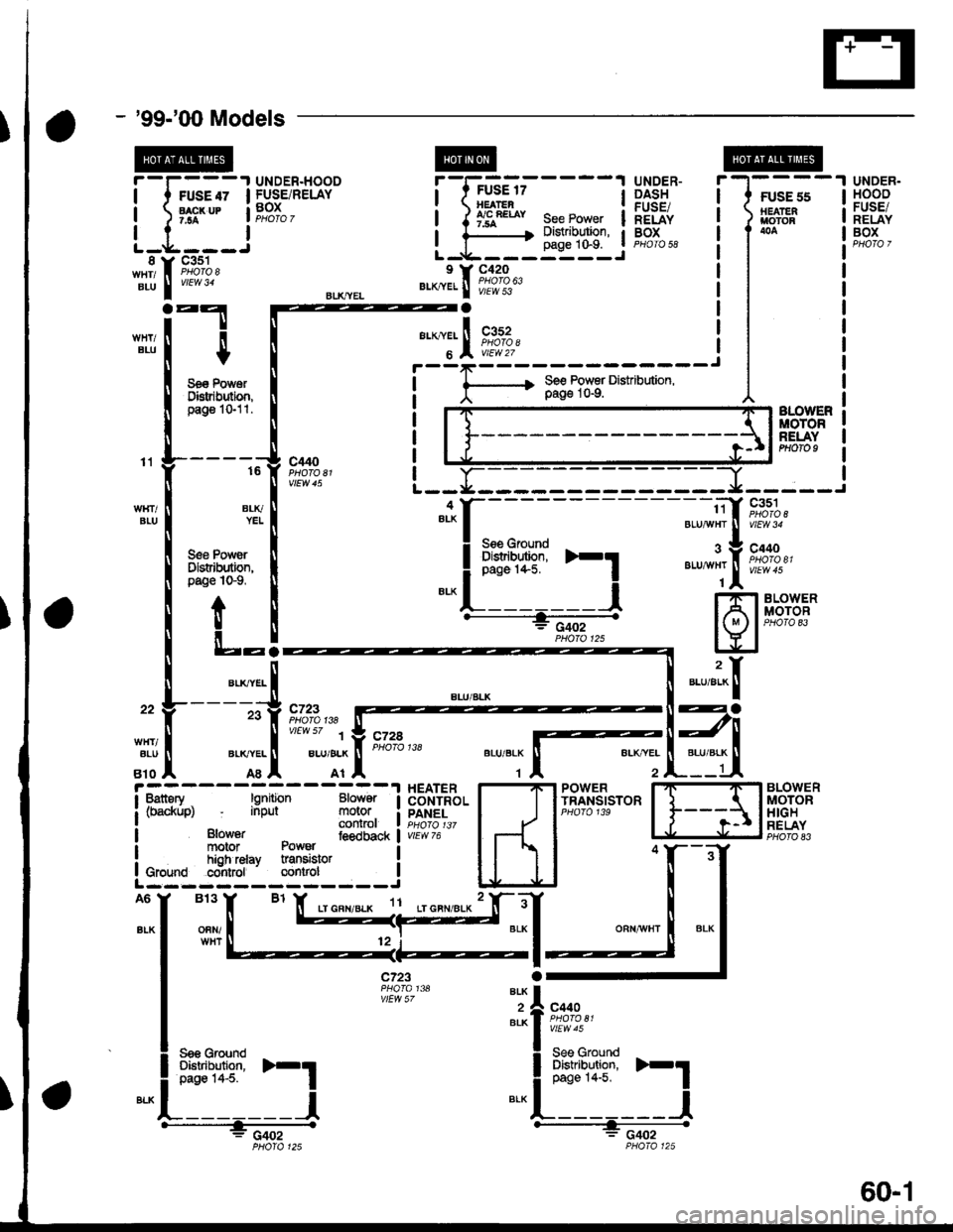
- '99-'00 Models
i-F;;t
L-t'::-i
"d[ft?"l'
UNDER.HOODFUSE/RELAYBOX
UNDER-DASHFUSE/RELAYBOXPHOTO 58
iGi'i'-----'lBEATEA,'/C RE|AY7.5A
".*1.[F*ft"
See PowerDist.ibution,
FUSE 55HEAIERt/toToR
page 10"9.L-*----::--J
BLU
n
$
Se€ PowsrDl8tdbution,pago 1O11.
g€e PowsrDlslribution,pag€ lGg,
ALOWEFmoToRREIAYPHOTO Il1
BIUBLIVYEI
813
OFN/WHT
BLK
2BIK
G402G402
"lSi:lf:::' >-1
-".. i c.u, I--';-lP;!o;i: I---------J
l ,f 3ffJ?il3'o'"o'o*'on
L __ f_---_-_ :::::: - --- r-- -- J
-f-***;
;Iru
I 'rr l-'n BLowER---:-----.l I A lm-o-roC'------------a---E eaoz - I( M rlProraE3PHoro 12s I Y I=----GG-a -
vtEvl 57c440
Se€ Ground
".","i-l'
Ea
JI
6BLOWERMOTORTIIGHRELAYPHO|O 83
UNDER.HOOOFUSE/RELAYBOX
t
!.-
1 HEATER I"-'FI POWERt Battory lgnition Blower I CONTROL I | | rAlHStStOni (brckup) input molor i pAHel I I I pHoro 13e
I ,,o*", _ ffJtt' t PHoro tr7 | tt I
i motor Power ' 'Jback I wr'vzo
I ;_ |! high relay transislor
Ls::s1gl-tt:---J lJ J I
A6
alK
See GroundOistribution,page '14-5.
za
60-1
Page 1952 of 2189
![HONDA CIVIC 1998 6.G Workshop Manual Air Delivery
- 99-00 Models
a
r--T----.I UNDER-HOOD UNDEB-DASH
| ,ry:i.l? IFUSE/RELAY I t::u:E^tt l:usE/RELAyi
- -{-;;; -
I PJ,.,8.J390 i
-
T;; ;
- - - - -
I H$3,,8
i 1;:t"* ];FPJ", i i m. HONDA CIVIC 1998 6.G Workshop Manual Air Delivery
- 99-00 Models
a
r--T----.I UNDER-HOOD UNDEB-DASH
| ,ry:i.l? IFUSE/RELAY I t::u:E^tt l:usE/RELAyi
- -{-;;; -
I PJ,.,8.J390 i
-
T;; ;
- - - - -
I H$3,,8
i 1;:t"* ];FPJ", i i m.](/manual-img/13/6068/w960_6068-1951.png)
Air Delivery
- '99-'00 Models
a
r--T----.I UNDER-HOOD UNDEB-DASH
| ,ry:i.l? IFUSE/RELAY I t::u:E^tt l:usE/RELAyi
- -{-;;; -
I PJ,'.',8.J390 i
-
T;; ;
- - - - -
I H$3,',8
i 1;:t"* ];FPJ", i i m'.u" se€power i "t8L,,
i t i a l'"0 r3l",lli"i:" aL--{..-----J L-J..----5::---:-J
"",":"rfi?ll, '[r;T:1"
-",*"1-J
*-*..l
,n", ".u I lt I
lr !I See Power I See Power Distnbution.I Distribution, U page 1o-9.
,, L::':l------- *Y=l
"*o "."",,t
[
*,:.'.Y%
Irel-
lt
:'l-4riffi
MODECONTROLMOTOR
;L:L{;I{,tt't{ {f
SensorGround grgund
venl
Air mix5Y poientia,reTgrano9 rnrrul
gIouno
RecircSwilcfi switchcommon mput
Recirc S$,itchtED LEDcontrol common
RECIRCULATIONCONTROLMOTORPHOTO 139
CONTROLPANEL
vtEw 76
So€ Roar II Windolv :
a
Htr Ttr =tr ;l *tr :tr *,tr THtr Ttr =tr ;l *tr :tr *tr Ttr
'il
Ti
Battery lgnition Mod€ Mode Mode L4ode Mode l od€(back up) input detrost h€av heat heav vent motorR€circulato Fresh
IJ
Delogger
L------- ---J
HEATERPUSHswtTcHEs
delrost
Air Airmix mixcool hot;;-; J'J - - - J-JL i- 5:- - -
SLK
812
AFN
13
BFN
See GroundDistribution,page 14-5.
c4 t, cl
WHT I ONN
ft++il
c723
F ash/RoclreSwftch
Reclrc.oat LEo
IY
tt
L__l--tGo3,
See RearWindowOetogger
AIR MIXTURECONTROLMOTOR
(
c9 Y cl1
61-2
Page 1957 of 2189
- How the Circuit Works
Battery voltage is supplied through tuse 56 to the
A,/C compressor clutch r€lay contacts at all times.
With the ignition switch in ON (ll), vollage is applied
to the coil of the A,/C compressor clutch relay
through fuse 17. When you push the A,/C switch
ON, and the heater fan switch is in position | , 2, 3,
or 4, a "ground" input is provided to the engine
control module (ECM) or powertrain control module
(PCM) through the l'lC thermostat and the l'lC
pressure switch.
The A,/C compressor clutch relay is grounded by the
engine control module (ECM) or powertrain control
module (PCM). When energized, the A'lC
compressor clutch relay allows battery voltage to
turn on the A,/C comDressor clutch.
The A,/C ON indicator light comes on when the A,/C
system is requested.
A,/C Thermostat
The A'lC thermostat is located on the evaoorator
housing. The A,/C thermostat turns off the A,/C
compressor clutch if the temperature at the
evaporator goes below 3'C (37'F). This prevents
condensation from freezing on the evaporator fins
and blocking the air delivery into the passenger
compartment. The blower motor will keep running
when the sensor turns off the comDressor.
A,/C Pressure Switch
The fuC oressure switch is located in the condenser
outlet line where refrigerant is in a high
temperature/high pressure liquid state. The switch
will sense abnormally high or low pressure, and
open the circuit. This removes ground, and the
compressor will stop running.
Thermal Protectot
The thermal protector, located on the A,/C
compressor, opens and turns the compressor off if it
senses high temperature. Once the compressor
cools, the switch will close and the compressor will
begin running again.
Refer to the Service Manual (Section 22,
Air Conditioning) for specific tests or
troubleshooting procedures.
62-3
Page 1958 of 2189
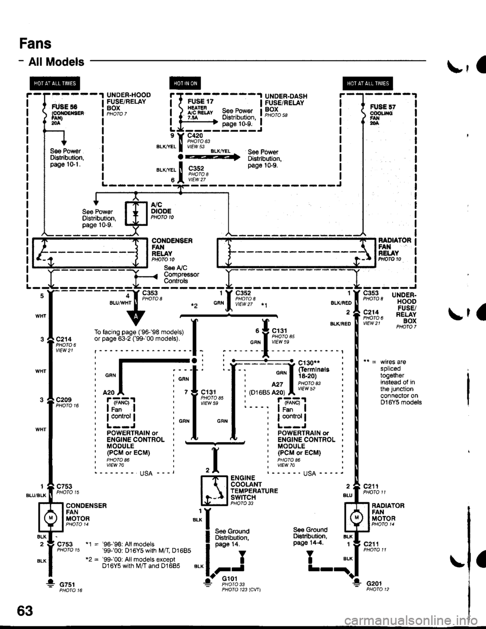
Fans
- AllModels\,1 |
splicedtogetherinstead of inthe junctionconnector onDl6Y5 models
c211PHOTO 11
FANRELAYPrtofo 10
Se€ I'i CCompre€sorCont ols
1
ALKAED
a
c352
f BLKaEou Y 9,;%,.cFN I vIEw 5e
;
"'
T
";::-:.."-!
Y:. ---::Y h!ii'in"," :
I : ""'I 'is.2o) :
I i,o''ur,ff;, l;l:'l?'* i
I r- - -, |JBEI :
I ; I control | ;
I :L--J :I ' PoWERTRAIN ordu. ' ENGINE CONTROL '' MODULE
: (PCMoTECM) :I PHAfO 86I wEw 7allqA ----.ENGINECOOLANTTEMPERATUREswtrcH BLLPHO|O 33 ?
Ses GrolndDiskibution,oaqe 14.
,I
H
:I
i:
"'*
1_l
c7531
BLU/BLK
ALK2
BLK
RADIATORFANMOTORI
BLK
BLK1
ELK
c753
CONDENSERFANMOTOR
a
* czsr
page 14.
II
FJ'Glot
c211
Gro!nd
T
Se€ GroundOstribution,Pago 14.4"t1 - '96.f98: All models'99-'00: 016Y5 with M/I 01685"2 = '99-'00: Allmodels exceptD16Y5 with M/T and 01685
cof{oENs€R
* czor33123lCVIl
63
Page 1961 of 2189
- How the Circuit Works
Radiator Fan
Voltage is provided at all times to the radiator fan
relay (contacts) through fuse 57. With the ignition
swilch in ON (ll), voltage is provided to the coil of
the relay through luse 17.
The radiator tan relay can be grounded through
either the engine coolant temperature switch or the
engine control module (ECM) or powertrain control
module (PCM).
The engine coolant temperature switch grounds
the radiator fan relay (coil) when the engine
coolant temperature exceeds 199'F (83'C). The
switch opens when coolanl temperature
decreases 3'- 8'C.
Condenser Fan
Voltage is provided at all times to the condenser fan
relay (contacts) through fuse 56. With the ignition
switch in ON (ll), voltage is provided to the coil of
the relay through fuse 17. When you push the A'lC
switch and put the heater fan switch in 1, 2,3, o( 4
position, the ly'C thermostat comes on, the
condenser fan relay energizes, and the condenser
fan motor runs.
A,/C Thermostat
The A,/C thermostat is located on the evaporator
housing. The A,/C thermostat tums off the A/C
compressor clutch if the temperature at the
evaporator goes below 3'C (37'F). This prevents
condensation from freezing on the evaporator fins
and blocking the air delivery into the passenger
compartment. lf the temperature goes below 3'C
(37"F) tuming off the Ay'C thermostat, ground will be
removed from the condenser fan relay. This will
deenergize the relay and remove voltage from the
condenser fan motor causing the fan to stop running.
Reter to the Service Manual (Section 23, Eleckical)
for specific tests or troubleshooting procedures.
63-3
Page 2014 of 2189
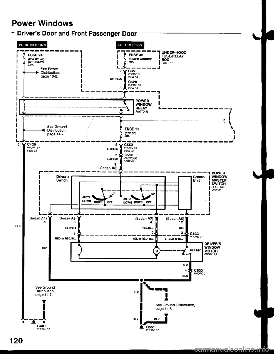
Power Windows
- Driver's Door and Front Passenger Door
FUSE 24
{s/n nElav)
Se€ PowefDistribution,page 106.
l' l-'G'-.i
- -
I i',I3.',8J39"
i ) lo1*" **oo*
i f,?T" ,
L-9------J'rF,*%,
*rtier-u |
'ry'
6I i[ff'3"
PowER !wtNDow IRELAYPHOfO 6S
see GroundDistribution,page 14-7.
I
I
I\
\
I
D ver'5SwitchContrslUnlt
POWERwtNDowMASTERswtTcrlPHATO 88vlEw 36
I
I
I
(Sedan A4)8(Sedan A5)
REO/^YEL
1
FED or aEO/BLU
(Sedan A7)4
RED/BLU
(Sedan A6)12
ALU
c633
YEL o. REo/YELLT BLU oT BLU
DRIVER'SwlNDowMOTOR
BLK
4
ALK
c633
See GroundDistribution,page 14-7.
I
I
I
See Ground Distibution,page 14€.
.---+<- G401PHOIA 57
0
c42O I Y C552
ii,?;?,* "., ".* ! f[fflo,u,
2 e C556".,,".* | f[ff11r,1 (Sedan A3) l
12
G551
Page 2017 of 2189

\
r--------.|UNDER.DASHr I FUSE/RELAY, I rur
t' f -,,--" J iFiona
5l'.il;;, i-l
l"o^ |L------- -"f-_-_=--_-=*"Er---,
vtEw 22
c570PHOfO 99
RIGHTREARwtNDowMOTOR
Motor has aself-resetiingcircurt breaker.
BLUMHT Ior REO nED/BLU
"ru"ao IorYEL2 neo,tea 4
c672
RIGHTREARwtNDowSWITCH
\,,YEI
I
YEL
A9POWERwtNDowMASTERSWITCH
vtEw 36
orowt{ofFUP
f
',
120-3
Page 2018 of 2189
Power Windows (contd)
- How the Circuit Works
CAUTION: You could iniure your arms, hands, or
fingers if you unintentionally switch the driver's
window to "automatic down" while working in
that door with the power on. Disconnect the
window switch conneclot or the battery when
working in the driver's door.
System Description
The operation of the power windows is controlled by
the main switch in the power window master switch.
When the main switch is in OFF, only the driver's door
window can be opened or closed. With the main
switch ON, all windows can be ooened or closed
either by swtches in the master panel, or swttches in
the doors. The driver's window switch also has an
automatic down mode which is tumed on by pushing
the switch down to its second oosition.
The power windows are driven by reversible motors.
Each motor is protect€d by a built-in circuit breaker.
lf the window switch is held on too long (with the
window obstructed, or after the window is fully up or
down), the circuit breaker opens the circuit. The
circuit breaker resets automaticallv as it cools.
Driver's Window
With the ignition switch in ON, voltage is provided to
the coil of the power window relay through fus€ 24.
The contacts of the power window relay close, and
voltage is applied to the driver's switch. When you
push the power window master switch to UP, voltage
is applied to the driver's window motor. (The motor's
ground path is back through the master power
window switch.) The driver's window motor then
drives the window up. When you push the switch to
DOWN, voltage is applied in the opposite direction
and the motor drives the window down.
Automatic Down (Driver's Window)
With the ignition switch in ON or START, voltage is
applied to the coil of the power window relay. The
contacts of the power window relay close and
voltage is applied lo the power window master
switch. When you push the driveas switch to the
AUTO DOWN position, voltage is applied through
the driver's switch to the driver's window motor. The
control unit receives pulses at the pulser input while
the motor is running. When the window is fully
down, the motor stops, and pulses are no longer
generated by the pulser. This is sensed by the
control unit at the pulser input, and voltage is no
longer applied to the driver's window motor.
Passenger Windows
With the ignition switch in ON, voltage is applied to
the coil of the power window relay through fuse 24.
The contacts of the power window relay then close,
applying voltage to the individual window switches
and the power window master switch. With the
master panel main switch ON, the passenger
windows can be ooerated from the individual
window switches or from tho master panel switches.
When you push the front passengsr's window
switch to UP, voltage is applied to the f ront
passenger's window motor. (The motor is grounded
through the contacts in the front passenger's
window switch and the oower window master
switch.) The window moves up as long as you hold
the switch in the UP position. lf you push the switch
to DOWN, voltage is applied in th€ opposite
direction to the front passenger's window motor, and
the window movss down as long as you hold the
switch in the DOWN Dosition. The window switches
in the other doors operate similarly.
When you push the front passenger's switch in the
master panel to UP, voltage is applied through the
front passenger's window switch contacts to the
front passengefs window motor. (The motor is
grounded through the contacts in the front
passenger's window switch and the power window
master switch.) The window moves up as long as
you hold the switch in the UP position. lf you push
the switch to DOWN, voltage is applied in the
opposite direction to lhe front passenger's window
motor, and the window moves down as long as you
hold the switch in the DOWN position. The other
passenger window switches in the master panel
operate similarly.
Refer to the Service Manual (Section 23, Electrical)
for specific tests or troubleshooting procedures.
120-4