1998 HONDA CIVIC Ground location
[x] Cancel search: Ground locationPage 1518 of 2189
Connector ldentification and WireHarness Routing
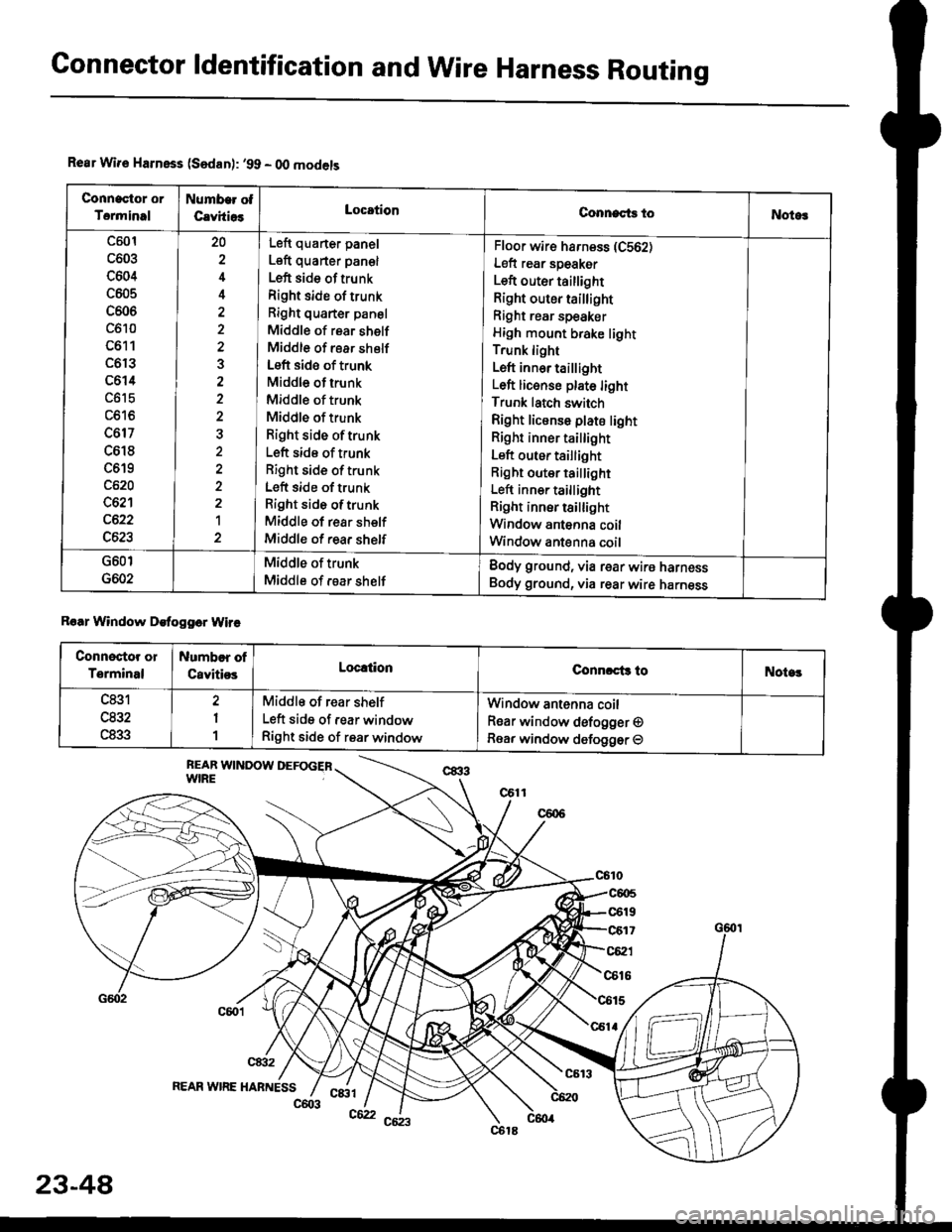
Rear Wir€ Harnsss (Sedan): '99 - O0 models
Connactor or
Torminal
Numb€r ot
CavhiosLocationConnects toNotog
c501
c603
c604
c605
c606
c610
c611
c6r3
c614
c617
c618
c619
c620
c621
c622
c623
20
4
3
2a
1
Left quarter panel
Left quarter pan€l
Left side of trunk
Right side of trunk
Right quarter panel
Middle of rear shelf
Middle of rear shelf
Left side of trunk
Middle of trunk
Middle of trunk
Middle of trunk
Right side oftrunk
Left side of trunk
Right side of trunk
Left side of trunk
Right side oftrunk
Middle of rear shelf
Middle of rear shelf
Floor wir€ harness (C562)
Left rear speaker
Left outer taillight
Right outer taillight
Right rear speaker
High mount brake light
Trunk light
Left inn6r taillight
Left licenso plate light
Trunk latch switch
Right license plate light
Right inner tai ight
Left outer taillight
Right outer taillight
Left inner taillight
Right inner tsillight
Window antenna coil
Window ant€nna coil
G601
G602
Middle of trunk
Middle of rsar shelf
Body ground, via rear wire harness
Body ground, via rear wire harness
Roar Window Detogger Wire
Connectot or
Terminal
Numbor of
CavitiosLoc!tionConnrct3 toNote!
c831
u65Z
c833
2
1
1
Middle of rear shelf
Left side of rear window
Right side of rear window
Window antenna coil
Rear window defogger O
Rear window defogger O
REAR WIRE HABNESSc&tl
23-48
c603c62
Page 1524 of 2189
Connector ldentification and Wire Harness Routing
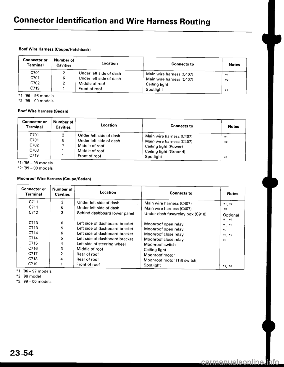
Roof Wire Harness (Coupe/Hatchback)
Connector ol
Terminal
Number of
CavitiesLocationConnects toNotes
c701
c701
c702
c719
2
6
2
1
Under left side of dash
Under left side of dash
Middle of roof
Front of roof
Main wire harness (C407)
Main wire harness (C407)
Ceiling light
S potlig ht*1: '96 - 98 models*2: '99 - 00 models
Roof Wire Harness (Sedanl
'96 - 98 models'99 - 00 models
*1: '96 - 97 models"2: '98 model*3: '99 00 models
*l:
+2:
Connector or
Terminal
Number of
CavitiesLocationConnects toNotes
c701
c701
c702
c703
c719
2
1
1
1
Under left side of dash
Under left side of dash
Middle of roof
Middle of roof
Front of roof
Main wire harness (C407)
Main wire harness (C407)
Ceiling light (Power)
Ceiling light (Ground)
Spotlighr
Moonroof Wire Harness {Coupe/Sedan}
Connector or
Terminal
Number ot
CavitiesLocationConnects toNotes
c711
c711
c1't2
c713
c713
c714
c714
c715
c117
c718
c719
2
6
6
5
5
4
3
2
4
1
U nder left side of dash
Under left side of dash
Behind dashboard lower panel
Left side of dashboard bracketLeft side of dashboard bracket
Left side of dashboard bracket
Left side of dashboard bracket
Left side of steering wheel
Middle of roof
Rear of roof
Rear of roof
Front of roof
Main wire harness (C407)
Main wire harness (C407)
Under-dash tuse/relay box (C910)
Moonroof open relay
Moonroof open relay
Moonroof close relay
Moonroof close relay
Moonroof switch
Ceiling light
Moonroof motor
Moonroof motor (Tilt switch)Sporlight
Optional
23-54
Page 1526 of 2189
Connector ldentificationand Wire Harness Routing
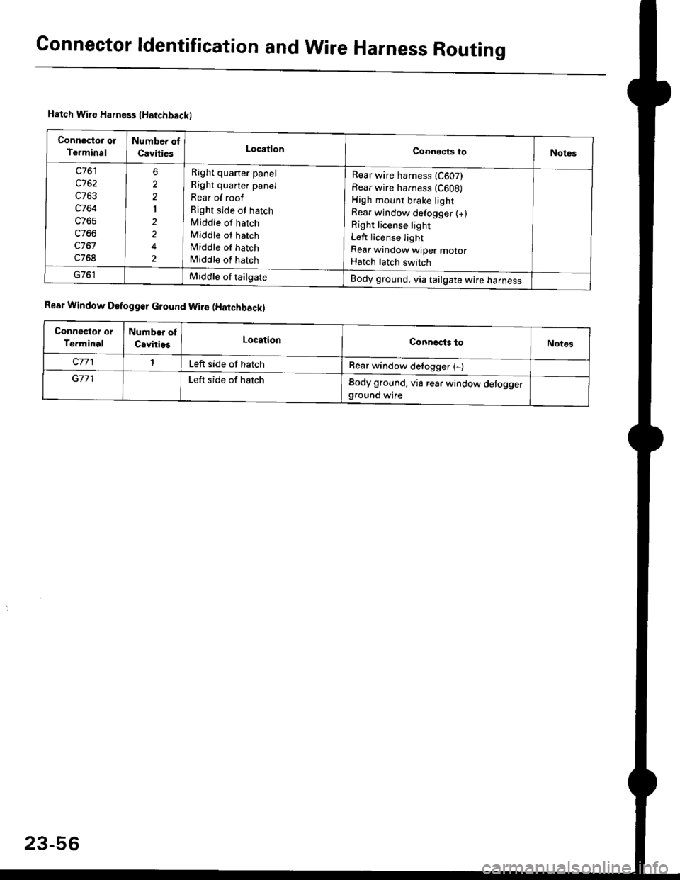
Hatch Wiro Harness (Hatchbackl
Connector or
T€rminal
Number of
CavitiesLocationConnects toNotes
c761
c762
c764
c768
6
2'|
2
2
Right quaner panel
Right quaner panel
Rear of roof
Right side of hatch
Middle of hatch
Middle ot hatch
lViddle of hatch
Middle of hatch
Rear wire harness (C607)
Rear wire harness (C608)
High mount brake light
Rea. window defogger (+)
Right license light
Left license light
Rear window wiper motor
Hatch latch switch
Middle of tailgateBody ground, via tailgate wire harness
Rear Window D€fogg€r cround Wir€ (Hatchbackl
Connoctor or
Terminal
Number oI
CavitiesLocationConnects toNotes
Left side ot hatchRear window defogger (-)
G171Left side of hatchBody ground, via rear window defoggerground wire
23-56
Page 1531 of 2189
rt
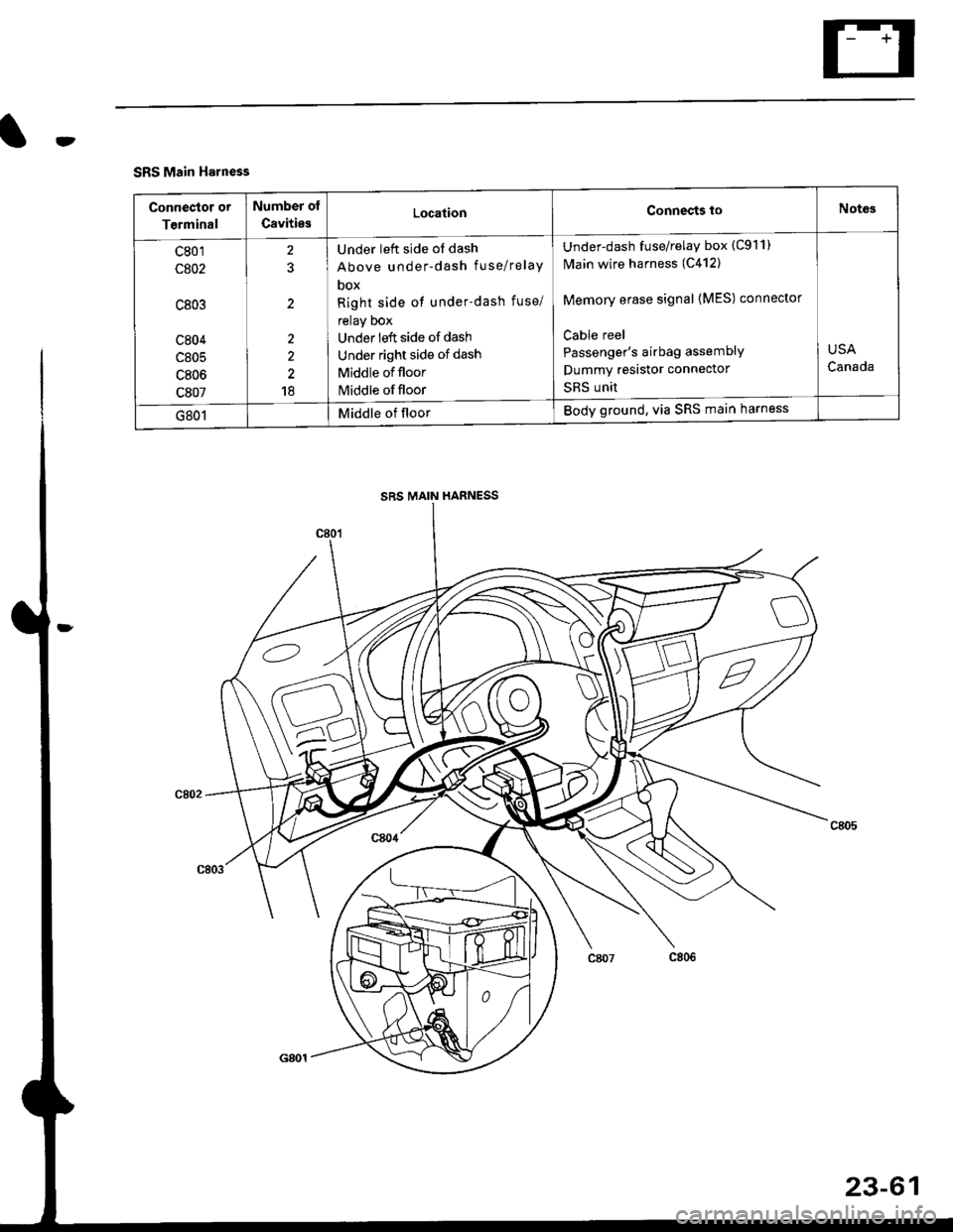
SRS Main Harness
Conneclor or
Terminal
Number of
CavitiesLocationConnects toNotes
c801
c802
c803
c804
c805
c806
c807
2?
2
2
2
18
Under left side of dash
Above under-dash fuse/relaY
DOX
Right side of under-dash fuse/
relay Dox
Under left side of dash
Under right side of dash
Middle of floor
Middle of floor
Under-dash fuse/relay box (C911)
N4ain wire harness (C412)
Memory erase signal {MES) connector
Cable reel
Passenger's airbag assemblY
Dummy resastor connector
SRS unit
USA
Canada
G801Middle of floorBody ground, via SRS main harness
SRS MAIN HARNESS
23-61
Page 1644 of 2189
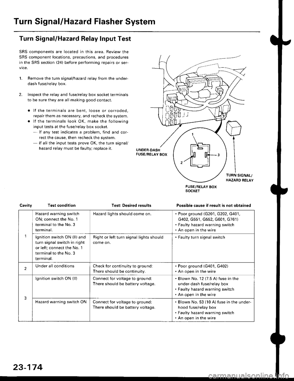
Turn SignallHazard Flasher System
1.
Turn Signal/Hazard Relay Input Test
SRS components are located in this area. Review the
SRS component locations, precautions, and procedures
in the SRS section {24} before performing repairs or ser-
vice.
Remove the turn signal/hazard relay from the under-
dash fuse/relay box.
Inspect the relay and fuse/relay box socket terminals
to be sure they are all making good contact.
. lf the terminals are bent, loose or corroded,
repair them as necessary, and recheck the system.
. lf the terminals look OK, make the following
input tests at the fuse/relay box socket.- lf any test indicates a problem, find and cor-
rect the cause, then recheck the system.- lf all the input tests prove OK, the turn signal/
hazard relay must be faulty; replace it.
Test: Desired results
FUSE/RELAY BOXSOCKET
Possible cause it result is not obtainedCavityTest condition
8Bffii
\_t-E rl.]l
| - lll
n'rl
,.ff T-'t:
Hazard warning switch
ON; connect the No. 1
terminal to the No.3
rermtnat.
Hazard lights should come on.Poor ground \G201, G202, G401,
G402, Gs51, G552, G601, G761)
Faulty hazard warning switch
An open in the wire
lgnition switch ON (ll) and
turn signal switch in right
or left; connect the No. 1
terminal to the No. 3
terminal.
Right or left turn signal lights should
come on.
. Faulty turn signal switch
2Under allconditionsCheck for continuity to ground:
There should be continuity.
. Poor ground (G401, G402). An open in the wire
3
lgnition switch ON (ll)Connect for voltage to ground:
There should be battery voltage.
Blown No. '12 (7.5 A) fuse in the
under-dash fuse/relay box
Faulty hazard warning switch
An open in the wire
Hazard warning switch ONConnect for voltage to ground:
There should be battery voltage.
Blown No. 53 (10 A) fuse in the under-
hood fuse/relay box
Faulty hazard warning switch
An open in the wire
23-174
Page 1747 of 2189
)
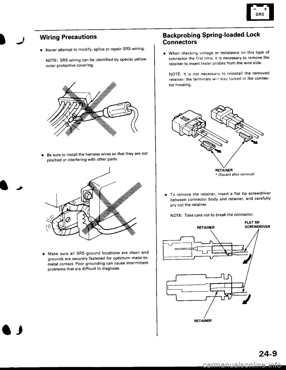
Wiring Precautions
. Never attempt to modify, splice or repair SRS wiring'
NOTE: SRS wiring can be identified by special yellow
outer Protective covering.
8e sure to install the harness wires so that they are not
oinched or interfering with other parts.
t
Make sure all SRS ground locations are clean and
grounds are securely fastened for optimum metal-to-
metal contact. Poor grounding can cause intermittent
problems that are difficult to diagnose.
a,
24-9
Backprobing Spring'loaded Lock
Gonnectors
. When checking voltage or resistance on this type of
connector the flrst time, it is necessary to remove lne
retainer to insert tester probes from the wire side.
NOTE: lt is not necessary to reinstall the removed
retainer; the terminals wi I stay locked in the connec-
tor housrng.
To remove the retainer, insert a flat tip screwdriver
between connector body and retainer, and carefully
pry out the retainer.
NOTE: Take care not to break the connector.
FLAT TIPSCBEWDRIVER
RETAINER* Discard after removal.
RETAINER
Page 1817 of 2189

Contents
How to Use This Manual ICircuit Schematics (see Circuit Index)Fuse/Relaylnformation 6Ground-to-Componentslndex 6-6ComponentLocationPhotooraohs 201Conriector Views 202
Circuit Index
Accessory power socket 155Air conditionerAir delivery'96198 models 61'99-'00 models 61-2Blower controls'96198 models 60'99100 models 60-1Compressor controls 62Fans 63Anti-lock brake system (ABS) 44A/T gear position indicatorCVT 89All except CVT 89-1Automatic transmission controlsAll '96-'98 models except CVT and GX 39All '99100 models except CVT 39-8All GX models 39-8'96-'�98 CVT 39-4'99100 cw 39-12Back-up lightsCoupe and Sedan 110Hatchback l'10-1Brake lightsAll Coupes and'96-'98 Sedans 110-15'99-'00 Sedans 110-16Hatchback 110-17Brake system indicator light'96198 models 7'1'99100 models 71-1Ceiling light 114-3Charging system 22Condenser fan 63Console lights 114Cruise control 34Dash lights 114Daytime running lights 110- 13Engine coolant temperature gauge 81-1Fog lights 110-10Front parking lights 110-2Fuel gauge 81-1Fuse/relay boxUnder-dash 6Under-hood 6-4Underhood ABS 6-3Gauges 81Ground distribution 14Ground-to-Componentslndex 6-6Hazard warning lightsAll except '99100 Sedans 110-6'99100 Sedans 110-8Headlights 110-12Headlight switch 100Heater - See Air ConditionerHorn'96197 models 40'98 model 40-1'99100 models 40-2lgnition key reminder 73lgnition systemAll '96198 models except Dl685 20All '99100 models except D16Y5 with Mn 2O-2All D1685 engines 20-2'99-'00 D 16Y5 with M/T 20
lndicators 80Integrated control unit 70lnterlock systemAll except'96J98 CVT 138'96198CVT 138-1License plate lightsAll Coupes and '96-'98 Sedans I l0-3'99100 Sedans 1 10-4Hatchback 110-5Low fuel indicator light 74Moonrool'96197 models |22'98-'00 models 122-1Odometer 81Oil pressure indicator light 80-3Power distributionBattery to ignition switch, fuses, and relaysFuses to relays and components 10-2Power door locksAll models without keyless entry 130'96-'98 models with keyless entry 130-2'99100 models with keyless entry 130-12Power mirrorsWithout detogger 141With defogger '141-2
Power windows 120Programmed fuel injection system (PGNr-Fl)All '96-98 models except D1685 23All '99-'00 models except D16Y5with M/T and D1685 24All D1685 engines 25'99100 D16Y5 with M/T 23Radiator fan 63Rear window defogger'96-,98 models 64'99100 models 64-1Seat belt reminder 73Security system'96.'98 USA HX, LX, EX 133'96-'98 Canada EX, Si 133'99TOO USA HX, LX, EX, DX.V Si 133-4'99100 Canada EX, Si 133-4All CX and DX models 133-8Speedometer 81Starting systemA./T (All except Dl685) 21A"/r (D16Bs) 21-1Manualtransmission 21-2Slereo sound system 150Supplemental rastraint system (SRS) 47Tachometer 81TailliqhtsAllboupes and'96-'98 Sedans 110-3'99100 Sedans 1 10-4Hatchback 110-5Trunk light 114-3Turn signal lightsAll except'99100 Sedans 110-6'99-'00 Sedans 1 10-8Vehicle speed sensor (VSS) 33Wiper/washerFront 91Rear 92
10
Page 1819 of 2189
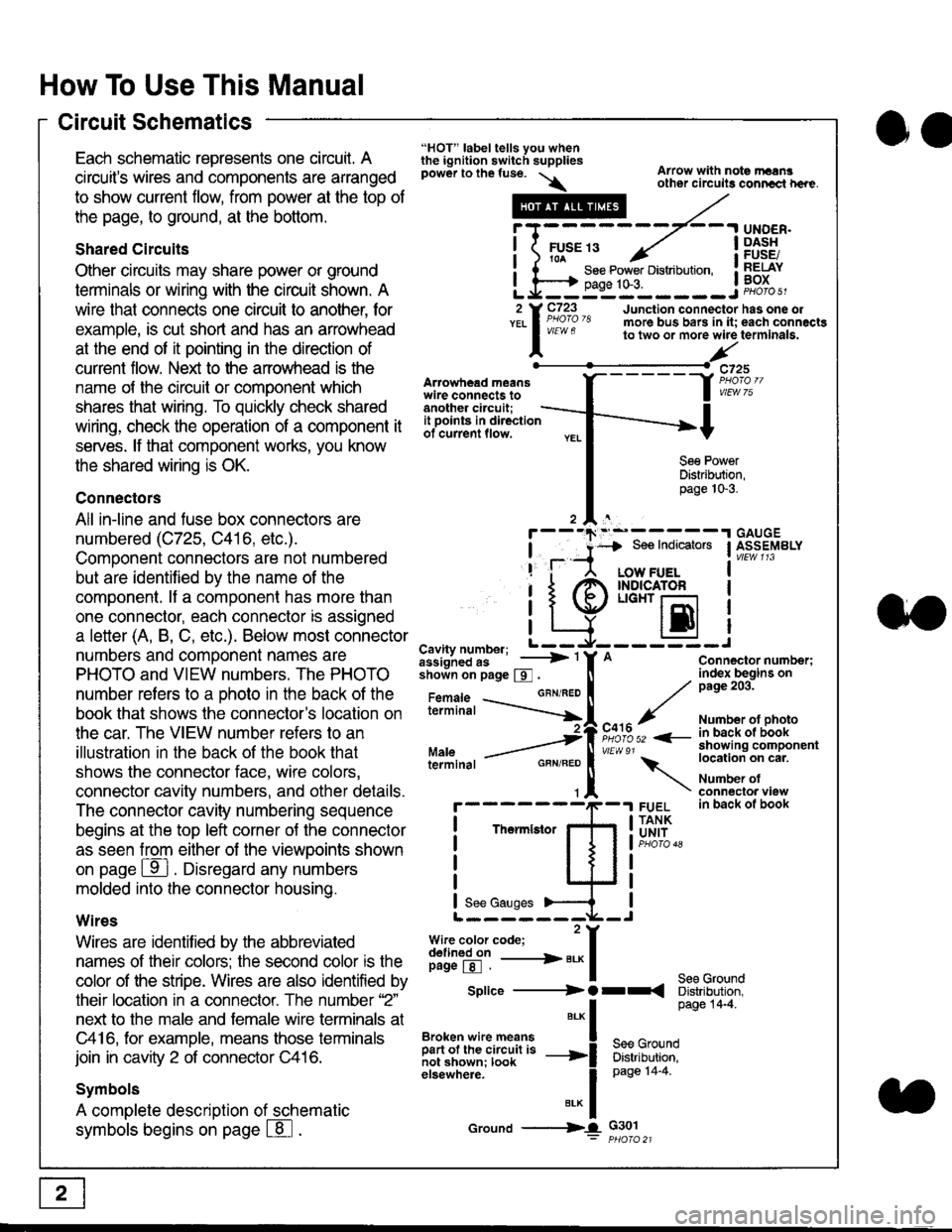
How To Use This Manual
Circuit Schematics
oa
Each schematic represents one circult. A
circuit's wires and components are arranged
to show current flow, from power at the top of
the page, to ground, at the bottom.
Shared Circuits
Other circuits may share power or ground
terminals or wiring with the circuit shown. A
wire that connects one circuit to another, for
example, is cut short and has an arrowhead
at the end of it pointing in the direction of
current flow. Nelit to the anowhead is the
name o{ the circuil or comoonent which
shares that wiring. To quickly check shared
wiring, check the operation of a component it
serves. lf that component works, you know
the shared wiring is OK.
Connectors
All in-line and fuse box connectors are
numbered (C725, C416, etc.).
Component connectors are not numbered
but are identiJied by the name of the
component. lf a componenl has more than
one connector, each connector is assigned
a letter (A, B, C, etc.). Below most connector
numbers and comDonent names are
PHOTO and VIEW numbers. The PHOTO
number refers to a Dhoto in the back of the
book that shows lhe conneclor's location on
the car. The VIEW number refers to an
illustration in the back of the book that
shows the connector face, wire colors,
connector cavity numbers, and other details.
The connector cavity numbering sequence
begins at the top left corner oJ the connector
as seen from either of the viewooints shown
on page ffl . Disregard any numbers
molded into the connector housino.
Wires
Wires are identilied by the abbreviated
names of their colors; the second color rs the
color of the stripe. Wires are also identified by
their location in a connector. The number '2"
next to the male and female wire terminals at
C416, for example, means those terminals
join in cavity 2 of connector C416.
Symbols
A complete description of schematic
symbols begins on page | 8
"HOT" label tells you whenthe ignition switch suppliespower to the fuse. \
Artowhead meanswire connects toanother circuit;
Arrow with note rErngother circuils conncct h€re.
it .a
llu":: ^,{ ii t See Power Distribution, .I t----t oaqe tO-3. IL*--:--------J2 Y C723 Junction connectorYEL I Pao'o'8 more bus bars in it;
I - " " to two or more wire
l,/
-t>?
See PowerDistribution,page 10-3.
UNDER.DASHFUSE/RELAYBOX
has one oleach connactgterminala.
it ooints in directionof current flow.
TheImletor
t_I
Cavity number; L ---
Jiili'iJi!--' -----> '
shoin on page S .
Maleterminal
L?*?l?,-
"'"'I
c725
vlEUt/ 75
Connector number;index begins onpage 203.
Number ot photoin back ol bookshowing componentlocation on cat.
Number ofconneclor viewin back of book
7
GBN/FEO
See Ground
Soe Indicators I ASSEMBLY
:-------J
LOW FUELINDICATOFLIGHT r-l
EI
A
"o'r"/PHOTO 52 <-
\
FUELTANKUNIT
Splice ---------) O rr
".* I Page 14'4'
IBroken wire means | --^ -
iar";J.'It,;,rJ;ii; -----i Bffi,Bili*l
elsewhere. I 0a0e tn-a
IBrK Icround --->lL c301: ptioro 21