1998 HONDA CIVIC ect sensor
[x] Cancel search: ect sensorPage 1973 of 2189
How the Gircuit Works
All Except GX
Do not smoke while working on the fuel system.
Keep open flame away trom the work area. Drain
fuel only into an approved container.
A thermistor is mounted in the fuel tank unit. When
the thermistor is cool, its resistance is very high.
When the thermistor's temperature increases, its
resistance decreases. Fuel in the fuel tank transters
heat away lrom the thermistor fast enough to keep it
cool so the thermistor's resistance stays high and
lhe low fuel indicator light does not come on. When
the fuel level drops below the thermistor, the
thermistor's temoerature increases. Without the fuel
to cool it, the thermistor's resislance decreases,
allowing current to llow through the low fuel
indicator light and the thermistor to ground, and the
low fuel indicator light comes on.
Refer to the Service Manual (Section 23, Electrical)
for specific tests or troubleshooting procedures.
GX
The PCM turns on the low fuel indicator light when
the fuel level is low. The PCM will also blink the
indicator light when a problem is detected by the
fuel tank pressure sensor or the fuel tank
temperature sensor.
Refer to the Service Manual GX Supplement
(Section 11 , Fuel and Emissions) for specific tests
or troubleshooting procedures.
74-1
Page 1980 of 2189
Gauges (cont'd)
- How the Gircuit Works
When the ignition switch is in ON (ll) or START (lll),
battery voltage is supplied through fuse 25 to the
gauges in the gauge assembly.
Speedometer and Odometer
The odometer and soeedometer drive circuits
receive pulses from the vehicle speed sensor
(VSS). The pulse rate increases as the car
accelerates. The frequency and duration of these
input pulses are measured and displayed by the
speedometer, odometer and tripmeter.
Tachometer
The tachometer drive circuit receives pulses from
the ignition control module (lCM) in the distributor
assembly or the ECM/PCM. The solid-state
lachometer then displays these pulses as engine
speed. For each 200 pulses per minute from the
ignition control modul€ (lCM) or the ECM/PCM, the
tachometer displays 100 RPM.
Engine Coolant Temperature Gauge
The engine coolant temperature gauge has two
intersecting coils wound around a permanent
magnet rotor. Voltage applied to the coils, through
fuse 25, generates a magnetic lield. The magnetic
field, controlled by the coolant temperature sending
unit, causes the rotor to rotate and the gauge
needle to move. As the resistance in the sending
unit varies, current through the gauge coils
changes. The gauge needle moves toward the coil
with the strongest magnetic field.
The 6ngine coolant temperature sending unit's
resistance varies from about 137 ohms at low
engine temperature to between 3H6 ohms at high
temperature (radiator fan running).
Refer to the Service Manual (Section 23, Electrical)
for specific tests or troubleshooting procedures.
81-2
(
Fuel Gauge (All except cX)
The fuel gauge has two intersecting coils wound
around a permanent magnet rotor. Voltage applied
to the coils, through tuse 25, generates a magnetic
field. The magnetic field, controlled by the fuel
gauge sending unit, causes the rotor to rotate and
the gauge needle to move. As the resislance in the
sending unit varies, current through the gauge coils
changes. The gauge needle moves toward the coil
with the strongest magnetic field.
The fuel gauge sending unit's resistance varies
from about 2-5 ohms at full, to about 110 ohms at
empty. When you turn the ignition switch off, the
gauge remains at the last reading until you turn the
ignition switch to ON (ll) or START (lll) again,
Refer to the Service Manual (Section 23, Electrical)
for specific tests or troubleshooting procedures.
Fuel Gauge (GX)
The fuel gauge has two intersecting coils wound
around a permanent magnet rotor. Voltage applied
to the coils, through fuse 25, generates a magnetic
field. The magnetic field, controlled by the PCM,
causes the rotor to rotate and the gauge needle to
move. The PCM calculates the gas quantity in the
fuel tank by using the fuel pressure value detected
by the tuel tank pressure sensor and the fuel
temperature value detected by the fuel tank
temperalure sensor, and outputs the signal to the
gauge assembly. The gauge needle moves toward
the coil with the strongest magnetic field.
When you turn the ignition switch off , the gauge
remains at the last reading until you turn the ignition
switch to ON (ll) or START (lll) again. When the
PCM detects a malfunction with the fuel pressure or
temperature, or detects a gas leak, the PCM
reduces the fuel meter to 0.
Refer to the Service Manual GX Supplement
(Section 11 , Fuel and Emissions) for specific tests
or troubleshooting procedures.
a
a
Page 2055 of 2189
How the Circuit Works
Arming the Security System
The security system can be armed:
r By pressing the remote control LOCK button
(if equipped)
. 20 seconds atter closing all doors (C)UDX only)
Arming with the Transmitter
The security system can be armed by removing the
ignition key from the ignition switch, closing all
doors and the trunk, and pressing the LOCK button
on the transmitter. When you arm the system in this
way, the remote control LED comes on, the status
LED flashes once per second, the parking lights
flash once. the doors lock. and the horn sounds
once if the beeo sound mode is on.
Passive Arming (CX and Dx only)
When you turn the ignition to OFF, remove the
ignition key from the ignition switch, and close all
the doors and the trunk; the system will
automatically arm itself 20 seconds after the trunk
or last door is closed. When you arm the system
this way, the status LED tlashes 4 times per second
during the exit delay time, and once per second
after the system is armed; the parking lights will
flash once to confirm that the system is armed.
Triggering the Alarm
Atter you've armed the system, it will trigger the
alarm if any door or the trunldhatch is opened. lf the
battery is disconnected when the system is armed or
in the alarm mode, reconnecting it will immediately
trigger the alarm. When the alarm is triggered, the
following will occur for 30 seconds:
. the horn sounds
o the parking lights flash once per second
. the status LED flashes hvice oer second
. the starter is disabled
After 30 seconds, the alarm will stop and the
system will rearm. Pressing the transmitter
UNLOCK button will disarm the svstem.
tlr
133-13
Disarming the System without the Remote
Transmitter (HX, LX, and EX)
You can disarm the system by turning the ignition
switch to ON (ll) and pressing the disarm/valet
switch on the right side ol the stereo tuner face. The
disarm switch will also disarm the svstem after the
system has been triggered.
Disarming the System with the Remote
Transmitter (Hx, Lx, Ex, DX-V, and Si)
Pressing the transmitter UNLOCK button will disarm
the system. The parking lights llash t\ivice if the
alarm has not been tnggered. The parking lights
flash three times if the alarm has been triggered.
The driver's door will unlock. lf you press the unlock
button twice, it will unlock all doors. lf a door is not
opened within 30 seconds, the system will lock all
doors and rearm.
Disarming the System (CX and DX only)
lf the system arms itself, there is a 20 second delay
after you open a door before the alarm will trigger.
To disarm the system in this mode, simply turn the
ignition switch to the ON position
ldentitying Tripped Sensors
The system identifies which sensor trips the alarm
by flashing the status LED. To display the trip
sensor flash code, press the disarm/valet switch 3
times within 5 seconds after the system has been
disarmed. The status sensor will blink according to
the followino codes:
SensorsNumber of Flashes
Door
TrunldHatch
System Switches
1 blink, pause, repeat
2 blinks, pause, repeat
3 blinks, pause, repeat
For further operating instructions, see the security
syslem owner's manual.
(cont'd)
Page 2108 of 2189
-
Component Connector View Index (Views begin on page 202-21
Connector View
ABS Control Unit........ ......63
Audio Unit ('99-'00 models) ......74
Combination Light Switch . . . . . . . . . . . . . . . 64
Combination Wiper Switch . . . . . . . . . . . . . . 65
Cruise Control Unit.... .....43
C\TTTransmission Solenoid ............. 25
Data Link Connector (DLC) ..... 48
Daytime Runnlng Lights Control Unit ..... 66
Engine control Module (ECM) ...........70
Exhaust Gas Recirculation (EGR) Valve
and Lift Sensor (D16Y5 Mfl, D1685) . . . . 10
Gauge Assembly .............71
HazardWarnlngSwitch,,. .,,,...,,,,... 32
Heater Control Panel ('96-'98 models) .....44
Heater Control Panel ('99-'00 models) ...., 76
Heater Fan Switch ('96-'98 models) ,,,.... 11
fniector Control Module (GX) ............77
I/
202-1
Connector View
Integrated Control Unit .......,. 67
f nterfock Control Unit .... ...... 26
Keyfess Door Lock Control Unit . . . . , . . . . . 75
Mode Control Motor ... ........'17
Moonroof Close Relay .. .......13
Moonroof Open Relay ... .......15
PGM-FI Main Relay .. .......... 18
Power Door Lock Conlrol Unil ..... ...... 37
Power Mirror Switch .,... ...... 33
Power Window Master Switch .,.........36
Powertrain Control Module (PCM) .......70
Security Control Unit ..., ..,,... 58
Security Starter Cut Belay ... ...,,,....,, 12
SRS Unit ............. 51
Stereo Radio Tuner ('96-'98 models) ...... 68
Transmission Control Module CICM) .....69
Page 2110 of 2189
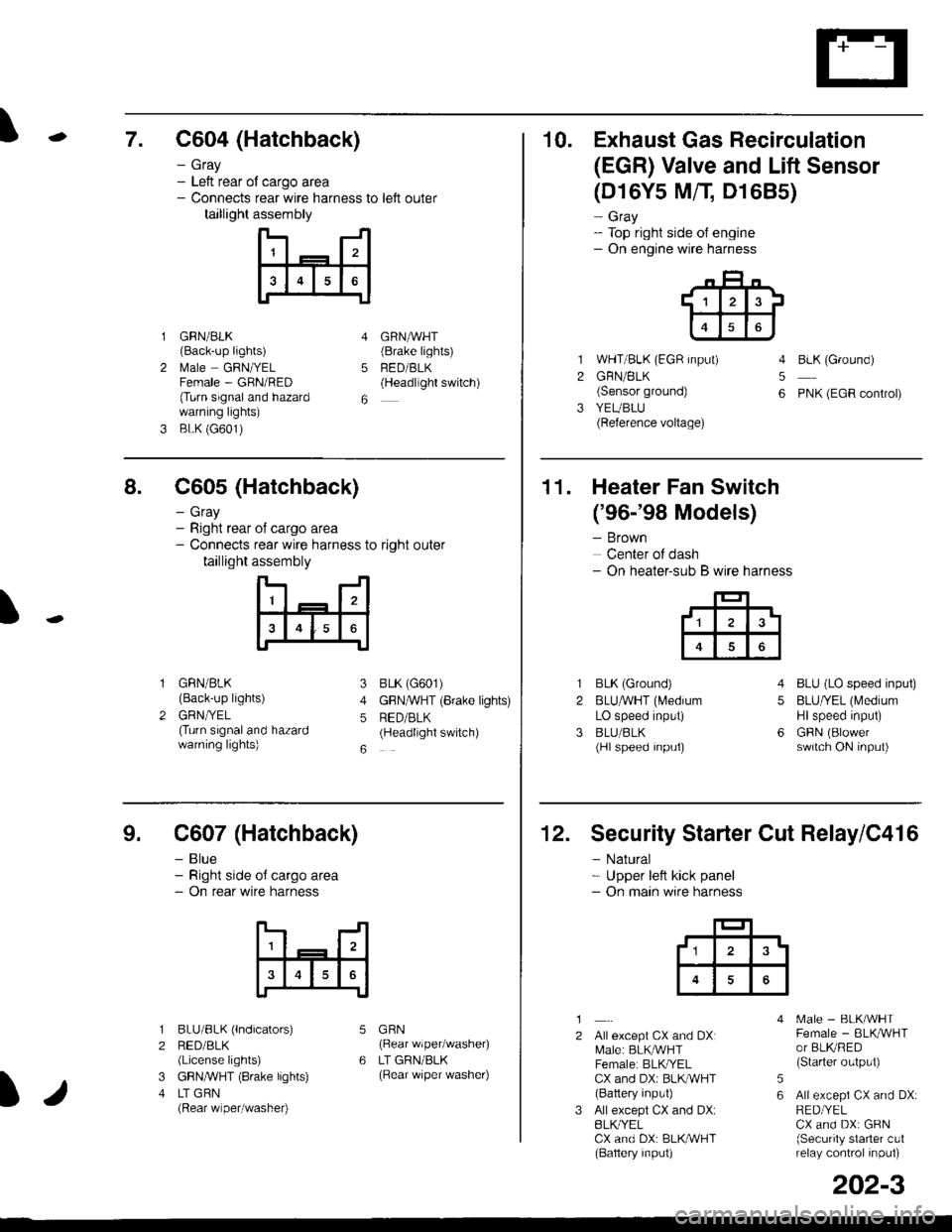
\7. C604 (Hatchback)
GRN/BLK(Back-up lights)
l\4ale GRNIYELFemale - GRN/RED(Turn signaland hazardwarning lights)
BLK (G601)
- Gray- Left rear ol cargo area- Connects rear wire harness to left outer
taillight assembly
4
5
6
1
2
GRNAVHT(Brake lights)
FED/BLK(Headllght switch)
10. Exhaust Gas Recirculation
(EGR) Valve and Lift Sensor
1
2
3
(D16Y5 MfI D1685)
- Gray- Top right side of engine- On engine wire harness
WHT/BLK (EGR input)
GRN/BLK(Sensor ground)
YEUBLU(Reference voltage)
4
5
6
BLK (Ground)
PNK (EGR control)
of cargo area
rear wire harness to right outer
assembly
n- -n
a t | _ a2a
l3I4t5tttl
IJ
I
8. C605 (Hatchback)
- Gray- Right rear- Connects
taillight
GRN/BLK(Back-up lights)
GRNTYEL(Turn signaland hazardwarning lights)
3
4
5
6
1
2
BLK (G601)
GFNAVHT (Brake lights)
RED/BLK(Headlight switch)
11. Heater Fan Switch
('96-'98 Models)
- Brown
Center of dash- On heater-sub B wire harness
BLK (Ground)
BLUAVHT (L4edium
LO speed input)
BLU/BLK(Hl speed input)
4
5
6
1
2
3
BLU (LO speed input)
BLU/YEL (Medium
Hlspeed input)
GFIN (Blowerswitch ON input)
9. C607 (Hatchback)
- Blue- Right side o{ cargo area- On rear wire harness
BLU/BLK (lndicators)
RED/BLK(License lights)
GBN,ryVHT (8rake lights)
LT GBN(Rear wiper/washe0
5
6
1
2
3
4
GRN(Rear wiper/washer)
LT GRN/BLK(Rear \/iper washer)
)/
202-3
12. Security Starter Cut Relay/C416
- Natural* Upper left kick panel- On main wire harness
1
2Allexcept CX and DXI[,4ale: BLK,^r'r'HTFemale: BLKI/ELCX and DXi BLI(WHT(Battery input)
All except CX and DX:BLK^/ELCX and DX: BLK/WHT(Baftery input)
[.4ale - BLK/WHTFemale - BLKAVHTor BLKRED(Starter output)
All excepi CX and DX:RED/YELCX and DX: GRN(Security starter c!1relay control inpul)
5
6
tl3'
Page 2112 of 2189
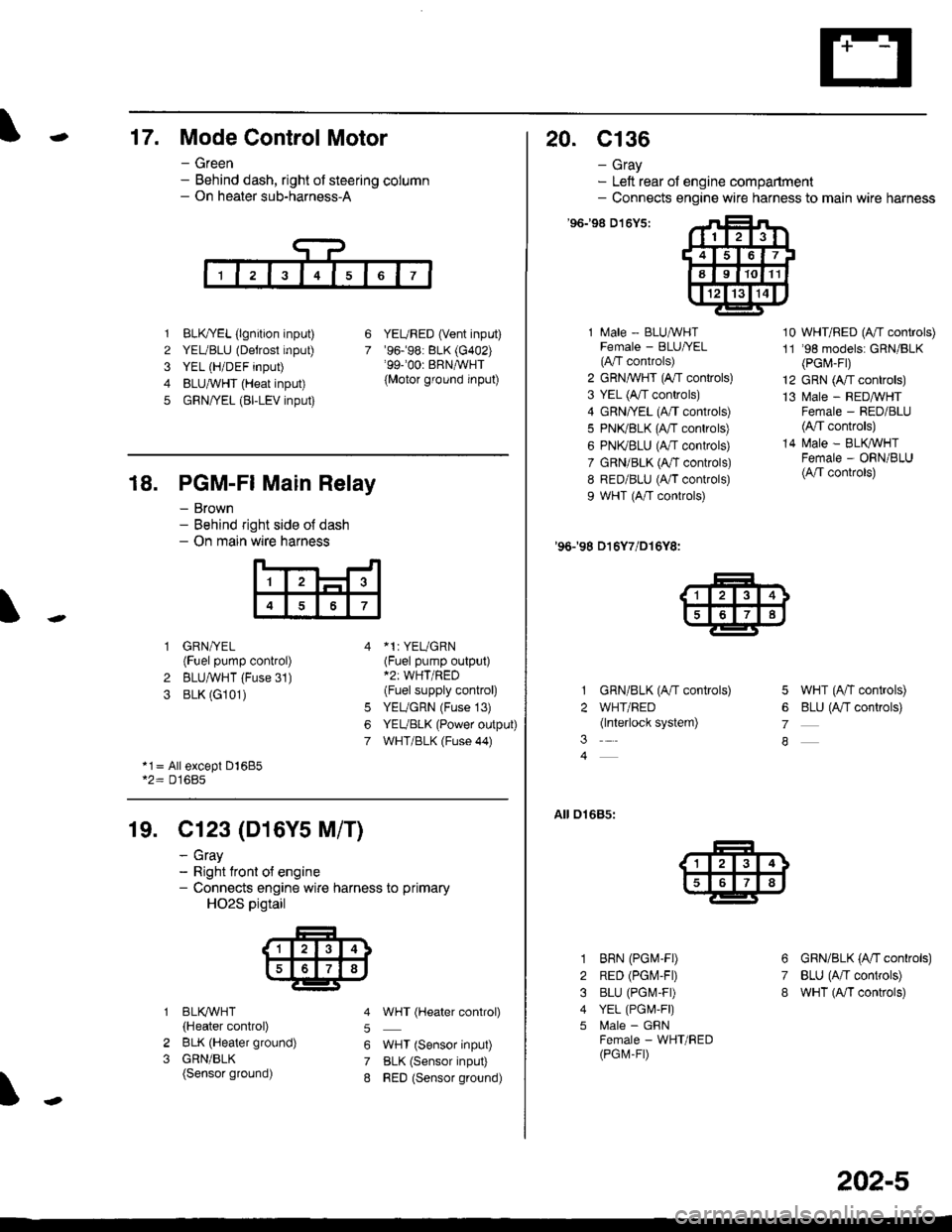
-17. Mode Control Motor
- Green- Behind dash, right of steering column- On heater sub-harness-A
1 BLK,TYEL (lgnition input)
2 YEUBLU (Detrost input)
3 YEL (H/DEF input)
4 BLUA/VHT (Heat input)
5 GRN/YEL (BI-LEV input)
YEURED (Vent input)'96.�98: BLK (G402)'99-'00r BRNAVHT
{Motor ground input)
6
7
18. PGM-FI Main Relay
- Brown- Behind right side o{ dash- On main wire harness
'l
4
1 GRN/YEL(Fuel pump control)
2 BLUAVHT (Fuse 31)
3 BLK (G101)
*1: YEUGRN(Fuel pump output)*2: WHT/RED(Fuel supply control)
YEUGRN (Fuse 13)
YEUBLK (Power output)
WHT/BLK (Fuse 44)
6
7
*1= All except Dl685*2= D16Bs
19. Cl23 (D16Y5 M/T)
2
3
BLI(WHT
{Heater control)
BLK (Heater ground)
GRN/BLK(Sensor ground)
- cray- Right tront o{ engine- Connects engine wire harness to primary
HO2S pigtail
5
6
7
8
WHT (Hgater control)
WHT (Sensor input)
BLK (Sensor input)
RED (Sensor ground)
20. c136
- Gray- Left rear of engine compartment- Connects engine wire harness to main wire harness
'96198 D't6Y5:
1 Male - BLUAVHTFemale - BLU|/EL(A"/T controls)
2 GRN,^WHT (A,/T controls)
3 YEL (A/T controls)
4 GRN/YEL (A/T controls)
5 PN(BLK (fff gs6lrq;s;
6 PNI(BLU (A/T controls)
7 GRN/BLK (Ar/T controls)
8 RED/BLU (A/T controls)
9 WHT (A/T controls)
'96198 D16Y7/D16Y8:
GRN/BLK (A/T controls)
WHT/RED(lnterlock system)
10 WHT/RED (A"/T controls)
11 '98 models: GRN/BLK(PGr,4-Fr)
12 GRN (A/T controls)
13 l\4ale - REDMHTFemale - RED/BLU(4,/T controls)
14 N4ale - BLIVWHTFemale - ORN/BLU(A/T controls)
5 WHT (A/T controls)
6 BLU (Antf se11re;s;
7
A
01685:
3
1
2
3
4
5
6
7
8
BRN (PGM-FD
RED (PGIV-FD
BLU (PGI\4-FD
YEL (PGI,4,F|)
l\4ale - GFNFemale - WHT/RED(PGM-FD
GRN/BLK (A'tl gs6trels;
BLU (A/T controls)
wHT (A/I controls)
202-5
Page 2115 of 2189
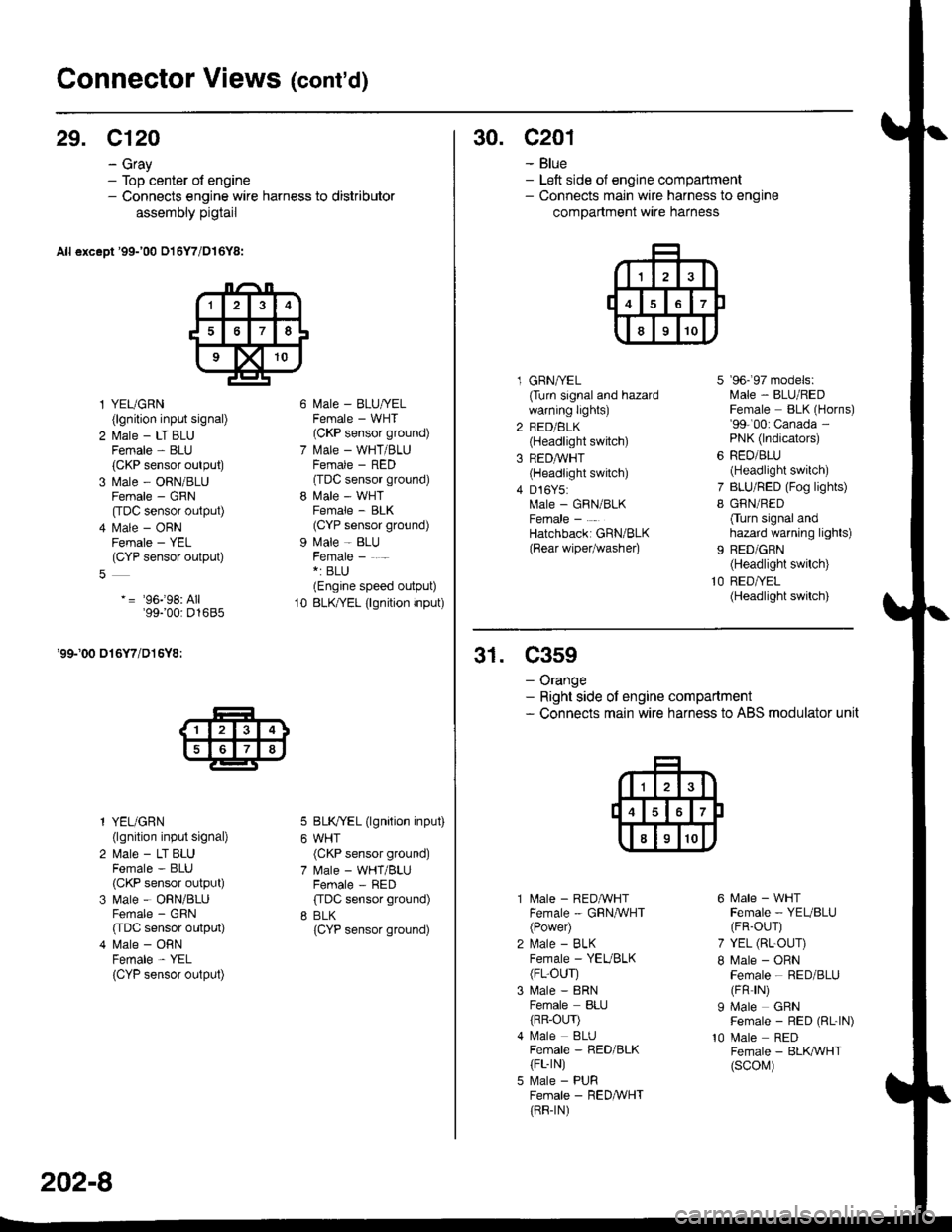
Connector Views (cont'd)
29. C120
- Gray- Top center of engine- Connects engine wire harness to distributor
assembly pigtail
All except '99-'00 016Y7/D16Y8:
l YEUGRN(lgnition input signal)
2 l\.4ale - LT BLUFemale - BLU(CKP sensor output)
3 Male - ORN/BLUFemale - GRN
[tDC sensor output)
4 l\.4ale - ORNFemale - YEL(CYP sensor output)
-= '96j98: All'99100: D1685
'99-'00 016Y7/D16Y8:
l YEUGRN(lgnition input signal)
2 Male - LT BLUFemale - BLU(CKP sensor output)
3 Male - ORN/BLUFemale - GRN
CIDC sensor output)
4 Male - ORNFemale - YEL
{CYP sensor output)
l\4ale - BLU/YELFemale - WHT(CKP sensor ground)
l\.4ale - WHT/BLUFCMAIE _ HtsL'(TDC sensor ground)
l\4ale - WHTFemale - BLK(CYP sensor ground)
Male - BLUFemale - . -*: BLU(Engine speed output)
BLK/YEL (lgnition input)
BLK/YEL (lgnition input)
WHT(CKP sensor ground)
Male - WHT/BLUFemale - RED
ffDC sensor ground)
BLK(CYP sensor ground)
10
202-8
30. c201
- Blue- Left side of engine compartment- Connects main wire harness to engine
compartment wire harness
l GRNA/EL(Turn signal and hazardwarning lights)
2 RED/BLK(Headlight switch)
3 REDAVHT(Headlight switch)
4 D16Y5:Male - GRN/BLKFemale -
Hatchbacki GRN/BLK
{Bear wipetwashe0
7
I
9b- 9/ mooets:lvlale - BLU/REDFemale BLK (Horns)'99-'00: Canada -
PNK (lndicators)
RED/BLU(Headlight switch)
BLU/RED (Fog lights)
GRN/RED
Cturn signal andhazard warning lights)
BED/GRN(Headlight switch)
RED/YEL(Headlight switch)
31. C359
- Orange- Right side ot engine compartment- Connects main wire harness to ABS modulator unit
10
l\4ale - REDAVHTFemale - GRNA/VHT(Power)
l\,4ale - BLKFemale - YEVBLK(FL-OUr)
Male - 8RNFemale BLIJ
{RR-OLrr)l\4ale BLUFemale - RED/BLK(FL-rN)
Male - PURFemale - RED&VHT(RR-rN)
6 Male - WHTFemale - YEUBLU(FR-OUr)
7 YEL (RL-OUr)
I Male - ORNFemale - RED/BLU(FR rN)
I Male GRNFemale - RED (RL-|N)
10 Male REDFemale - BLK,ryVHT(scol\,1)
Page 2125 of 2189
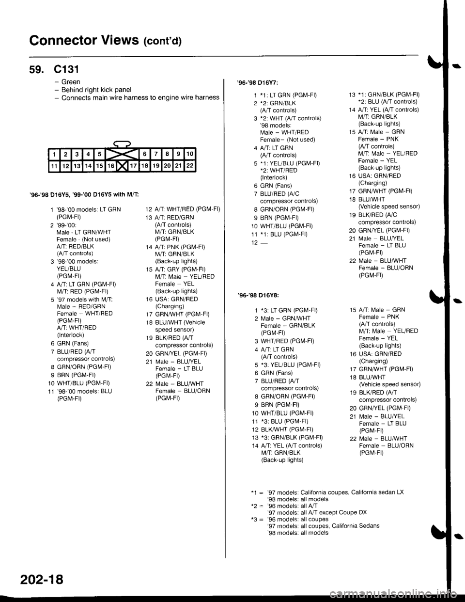
Connector Views (cont'd)
59. Cl31
- Green- Behind right kick panel- Connects main wire harness to engine wire harness
'96.'98 D16Y5,'99-'00 D16Y5 with M/T:
1 '98-'00 models: LT GRN(PGl\4-Fl)
2'991001Male'LT GRNMHTFemale (Not used)A/Tr RED/BLK(A/T controls)
3 '98r00 models:YEL/BLU(PGrV-Fr)
4 A/T: LT GRN (PGl\.4-Fl)
lVl/T: RED (PGi.4-Fl)
5 '97 models with l\4/T:Male - RED/GRNFemale - WHT/BED(PGl\,4-Fl)
A/T: WHT/RED(lnterlock)
6 GRN (Fans)
7 BLU/RED (A/T
compressor controls)
I GFN/OnN (PGl\4-Fl)
I BRN (PGr\,4-Fr)
10 WHT/BLU (PGM-Fl)
11 '98-'00 models: BLU(PGir-Fr)
12 A,/T: WHT/RED (PG|VI-FD
13 A/T: RED/GRN(A/T controls)M/T: GRN/BLK(PGr\,1-Fr)
14 A/T: PNK (PGM-FDM/T; GRN/BLK(Back-up lights)
15 A/T: GRY (PGl\,l-Fl)
l\,4,rT: Male - YEUREDFemale YEL(Back-up lights)
16 USA GRN/RED(Charging)
17 GRN,ryVHT (PGM FD
18 BLUAVHT (Vehicle
speeo senso4
19 BLK/RED (A,IT
compressor controls)
20 GRN/YEL (PGM-FD
21 N,4ale - BLU/YELFemale - LT BLU(PGM-Fr)
22 Male - BLU/WHTFemale BLU/ORN(PGt4,Ft)
202-18
'96.'98 016Y7:
1 *1: LT GRN (PGM-F|)
2 *2: GRN/BLK(A/T controls)
3 *2: WHT (A/T controls)'98 models:[rale - WHT/REDFemale- (Not used)
4 A/Ti LT GRN(A/T controls)
5 *1i YEL/BLU (PGM-Fl)*2: WHT/RED(lnterlock)
6 GRN (Fans)
7 BLU/RED (A/C
compressor controls)
I GRN/ORN (PGlvl-Fl)
9 BRN (PGT,I-FD
10 WHT/BLU (PGM-Fl)
11 *1r BLU (PGL4-F|)
'96-'98 016Y8:
1 *3: LT GRN (PGlvl'Fl)
2 lvlale - GRNIVHTFemale - GRN/BLK(PGr\.4,F1)
3 WHT/RED (PGl\,4-F0
4 A"rT: LT GHN(A/T controls)
5 *3: YEUBLU (PGM-Fl)
6 GRN (Fans)
7 BLU/RED (A/T
compressor controls)
8 GRN/ORN (PGr\4'F|)
9 BRN (PG|\4-F|)
10 WHT/BLU (PG[,4-Fr)
11 *3: BLU (PG[.4-F|)
12 BLK,ryVHT (PGl\4-Fl)
13 *3r GBN/BLK (PGM-Fl)
14 A/T: YEL (A,rT controls)M/T: GRN/BLK(Back-up lights)
13 *1i GFN/BLK (PGl\4'Fl)*2: BLU (A/T controls)
14 A/Ti YEL (A/T conlrols)M/T: GRN/BLK(Back-up lights)
15 A/Ti Male - GRNFemale - PNK(A/T conkols)lvl/tT: Male - YEL/REDFemale - YEL(Back up lights)
16 USA: GRN/BED(Charging)
17 GRN,^/VHT (PGIVI.FD
18 BLU,ryVHT(Vehicle speed sensor)
19 BLI(RED (A/C
compressor controls)
20 GRN/YEL (PGM-Fr)
21 ftIale BLUffELFemale - LT BLU(PGM,Fl)
22 Male - ELUMHTFemale - BLU/ORN(PGrvl,Fr)
15 A/Tr l\,4ale - GRNFemale - PNK(A/T controls)lVl/T: [/ale YEUBEDFemale - YEL(Back'up lights)
16 USA: GRN/RED(Charglng)
17 GRN,ryVHT (PG[r-Fl)
18 BLUAVHT(Vehicle speed senso4
19 BLK/RED (A/T
compressor controls)
20 GRN/YEL (PG[' Fl)
21 Male - BLU//ELFemale - LT BLU(PGr,1-FD
22 l\,4ale - BLUMHTFernale BLU/ORN(PGt
-Ft)
*1 = '97 models: California coupes, Californla sedan LX'98 modelsi all models*2 = '96 models: all A,rT'97 modelsr all A"lT except Coupe DX*3 = '96 models: allcoupes'97 models: all coupes, California Sedans'98 models: all models