1998 HONDA CIVIC main fi
[x] Cancel search: main fiPage 1738 of 2189
Power Door Locks
Transmitter Programming ('99 - 00 modelsl
Storing transmitter codes;
The codes of up to three transmitters can be read into
the keyless receiver unit memory. (lf a fourth code is
stored, the code which was input first will be erased.)
NOTE: lt is important to maintain the time limits
between the steps.
'1. Turn the ignition switch ON (ll).
2. Within 1 to 4 sec., push the transmitter lock or unlock
button with the transmitter aimed at the vehicle.
3. Within I to 4 sec., turn the ignition switch OFF.
4. Within 1 to 4 sec., turn the ignition switch ON 1ll).
5. Within 1 to 4 sec., push the transmitter lock or
unlock button with the transmitter aimed at the
vehicle.
6. Within 1 to 4 sec., turn the ignition switch OFF.
7. Within 4 sec., turn the ignition switch ON (ll).
8. Within 1 to 4 sec., push the transmitter lock or
unlock button with the transmitter aimed at the
vehicle.
9.Within 1 to 4 sec., turn the ignition switch OFF.
Within 4 sec., turn the ignition switch ON (ll).
Within '1 to 4 sec., push the transmitter lock or
unlock button with the transmitter aimed at the
vehicle.
Confirm you can hear the sound of the door lock
acIuarors.
Within 8 sec., aim the transmitters (up to three)
whose codes you want to store at the receiver, and
press the transmitter lock or unlock buttons.
Contirm that you can hear the sound of the door
lock actuators after each transmitter code is stored.
Turn the ignition switch OFF, and pull out the key.
Confirm proper operation with the new code(s).
'10.
11.
12.
14.
23-268
Page 1741 of 2189
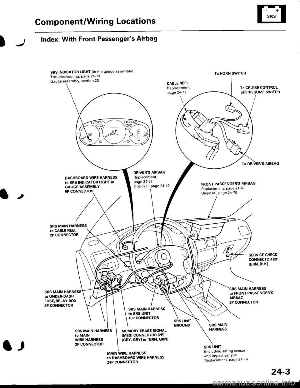
Component/Wiring Locations
)
Index: With Front Passenger's Airbag
SRS INDICATOR LIGHT (ln the gauge assemblvl
Troubleshooting, Page 24 13
Gauge assembly, section 23CABLE REEL
Replacemenlpage 2!-t 2
To HORN SWITCH
SRS UNIT(lncluding safing sensor
and imPact sensorl
Replacement Page 24 76
To DRIVER'S AIRBAG
DASHBOARD WIRE HARNESS
to SRS INDICATOB LIGHT in
GAUGE ASSEMBLY5P CONNECTOB
DBIVER'S AIRBAG
Beplacement,page 24-61Disposal, page 24 70FRONT PASSENGER'S AIBBAG
Replacement, Page 24_67
Disposal, Page 24 70
t
SRS MAIN HARNESSto CABI-E RE€L2P CONNECTOR
SRS MAIN
SERVICE CHECKCONNECTOR {2PI
IBRN, BLK]
to UNOER-OASHFUSE/RELAY BOX2P CONNECTOR
SRS MAIN HARNESSto FRONT PASSENGER'SAIRBAG2P CONNECTOB
SRS MAIN HARNESSto SRS UNITr8P CONNECTOR
SBS MAIN HARNESSto MAINWIRE HARNESS3P CONNECTOR
MEMORY ERASE SIGNAL(MES) CONNECTOR I2P)
[GRY, GRYI or IGRN. GRNI
MAIN WIRE HARNESSto DASHBOARD WIRE HARNESS
24P CONNECTOR
2+3
t,
Page 1742 of 2189
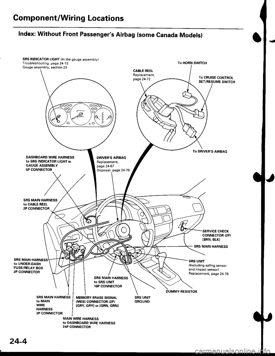
Gomponent/Wiring Locations
Index: Without Front Passenger's Airbag (some Canada Modelsl
SRS INDICATOR LIGHT (ln the gauge assembly)Troubleshooting, page 24-13Gauge assembly, section 23
DRIVER'S AIRSAGReplacement,page 24-67Disposal, page 24-70
SRS UNITGROUNO
To HORN SWITCH
SRS MAIN HARNESS
SRS UNIT{lncluding safing sensorand impact sensor)Replacement. page 24,76
To CRUISE CONTROLSET/RESUME SWITCH
oo/ \oo
To DRIVER,S AIRBAG
DASHBOARD WIRE HARNESSto SRS INDICATOR LIGHT inGAUGE ASSEMBLY5P CONNECTOR
SERVICE CHECKCONNECTOR {2P}IB8N, BLKI
SRS MAINto UNDER-DASHFUSE/RELAY BOX2P CONNECTOR
SRS MAIN HARNESSto SRS UNIT18P CONNECTOR
SRS MAIN HARNESSto MAINWIREHARNESS3P CONNECTOR
MEMORY ERASE SIGNAL(MES) CONNECTON (2P'
IGRY, GRYI o. IGRN, GRNI
MAIN WIRE HARNESSto DASHBOARD WIRE HARNESS24P CONNECTOR
24-4
DUMMY RESISTOB
Page 1743 of 2189
Description
)
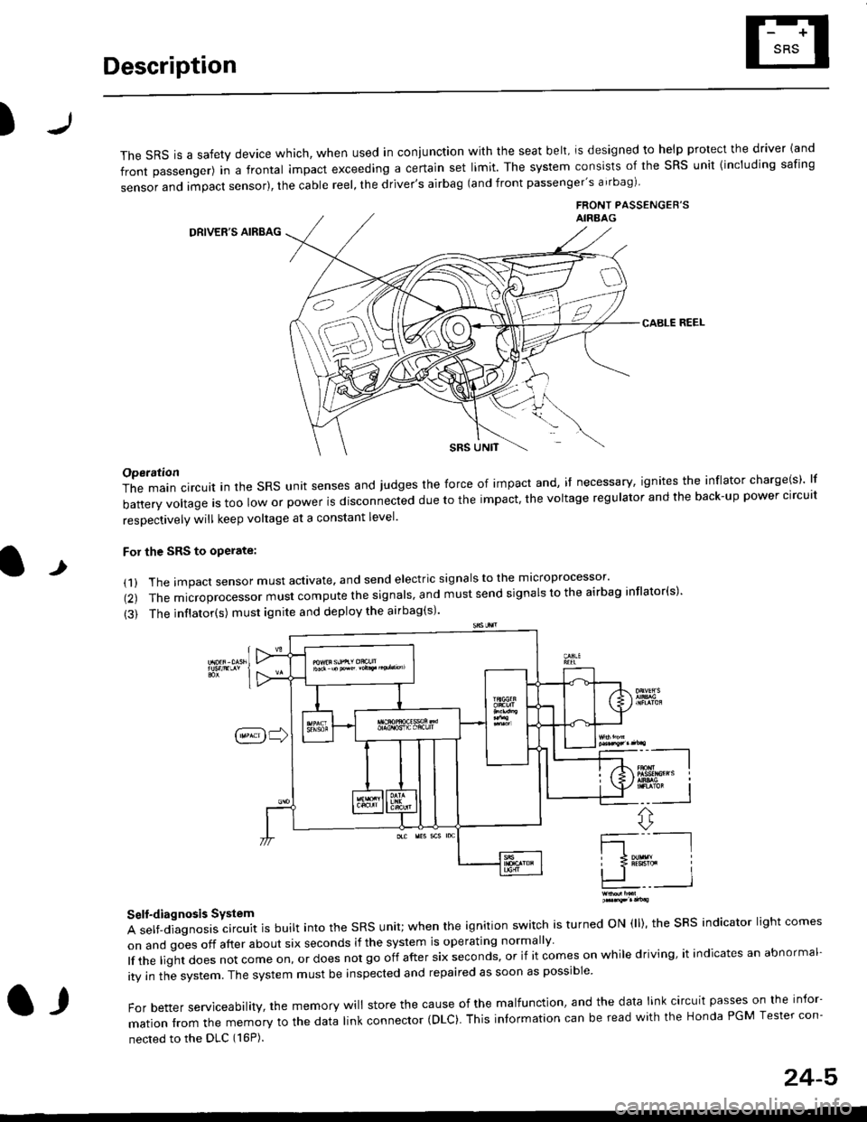
The sRS is a safety device which, when used in coniunction with the seat belt, is designed to help protect the driver land
front passenger) in a frontal impact exceeding a certain set limit. The system consists of the sRS unit {including safing
sensor and impact sensor), the cable reel, the driver's airbag (and front passenger's airbag)
FRONT PASSENGEB'SAIRAAG
DRIVER'S AIRBAG
CABLE REEL
SRS UNtT
t
Operation
The main circuit in the SRS unit senses and judges the force of impact and, if necessary, ignites the inflator charge(s) lf
battery voltage is too low or power is disconnected due to the impact, the voltage regulator and the back-up power clrcult
resoectivelv will keep voltage at a constant level.
For the SRS to operate:
(1) The impact sensor must activate. and send electric signals to the mlcroprocessor'
(2) The microprocessor must compute the signals' and must send signals to the airbag inflator(s)'
{3) The inflator(s) must ignite and deploy the airbag(s)'
_"-_-l
Ir3B!#h i
!.. I
ffi,*
Self-diagnosis System
A self-diagnosis circuit is built into the SRS unit; when the ignition switch is turned ON (ll), the SRS indicator light comes
on and goes off after about six seconds if the system is operating normally
lf the liglt does not come on, or does not go off after six seconds, or if it comes on while driving, it indicates an abnormal-
ity in the system. The system must be inspected and repaired as soon as possible
For better serviceability, the memory will store the cause of the malfunctlon, and the data link circuit passes on the infor-
mation from the memory to the data link connector (DLC). This intormation can be read with the Honda PGM Tesler con-
nected to the DLC (16P).
l,
24-5
Page 1749 of 2189
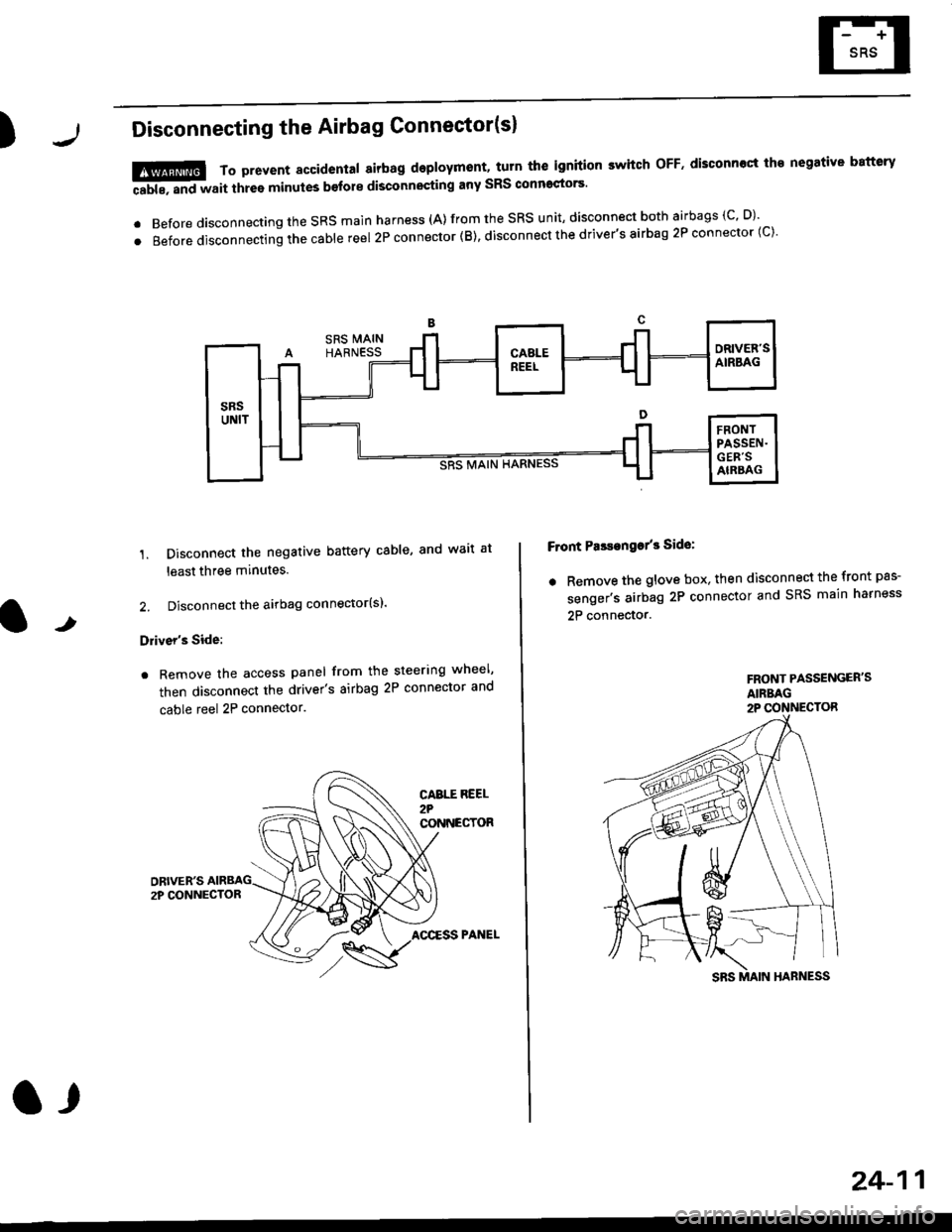
)Disconnecting the Airbag Connector(sl
'1. Disconnect the negative battery cable, and wait at
least three minutes.
2. Disconnect the airbag connector(sl.
Driver's Side:
. Remove the access panel from the steering wheel'
then disconnect the driver's airbag 2P connector and
cable reel 2P connector.
!@@ To prevent sccidental 8irbag deployment, turn th€ ignition switch oFF. disconncct th€ negative battery
ffi, "nd *"it thr"e minutes b€fore disconnocting any sRS conn'ctors'
. Before disconnecting the SRS main harness (A) from the SRS unit' disconnect both airbags (C' D)'
.Beforedisconnectingthecab|ereel2Pconnector(B),disconnectthedriver,sairbag2Pconnector(c).
F ont PasEanga/3 Side:
. Remove the glove box. then disconnect the front pas-
senger's airbag 2P connector and SRS main harness
2P connector.t
FRONT PASSENGER'SAIRBAG2P CONNECTOR
CABTT REEL2?CONNECTOR
AOCESS PANEL
a,
24-11
Page 1750 of 2189
Precautions/Procedu res
Steering-related Precautions
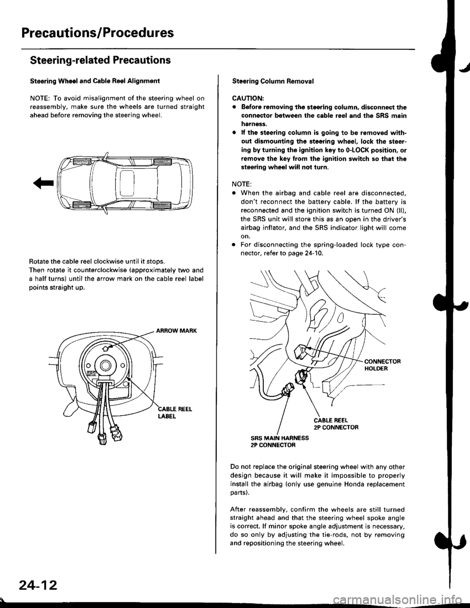
Stesring Wheel and Cable Reol Alignment
NOTE: To avoid misalignment of the steering wheel on
reassembly, make sure the wheels are turned straight
ahead before removing the steering wheel.
Rotate the cable reel clockwise until it stops.
Then rotate it counterclockwise {approximately two and
a half turns) until the arrow mark on the cable reel label
points straight up.
24-12
:l
St€€rin9 Column Removal
CAUTION:
. Eefore removing thg stggring column. disconnect the
connsstor bqtween the cable r€el and th€ SRS msin
harness.
. lf the stoering column is going to be romoved with-
out dismounting th6 stoering wheel, lock the steer-
ing by turning the ignition key to o-LOCK position, or
remove the key trom the ignition switch so that the
steering wheel will not turn.
NOTE:
When the airbag and cable reel are disconnected,
don't reconnect the battery cable. lf the battery is
reconnected and the ignition switch is turned ON (ll),
the SRS unit will store this as an open in the driver's
airbag inflator, and the SRS indicator light will come
on.
For disconnecting the spring-loaded lock type con-
nector, refer to page 24-'10.
SRS MAIN HARNESS2P CONNECTOR
Do not replace the original steering wheel with any other
design because it will make it impossible to properly
install the airbag (only use genuine Honda replacement
parts).
After reassembly, confirm the wheels are still turned
straight ahead and that the steering wheel spoke angle
is correct. lf minor spoke angle adjustment is necessary,
do so only by adjusting the tie-rods, not by removing
and repositioning the steering wheel.
Page 1751 of 2189
rl
Troubleshooting
t)
Self-diagnostic Procedures
The self-diagnostic function of the SRS system allows it to locate the causes of system problems and to store this informa' I
tion in memory. For easier troubleshooting, this data can be retrieved via a data link circuit l
. When you turn the ignition switch ON (ll), the SRS indicator will come on. ll it goes off after six seconds. the system is
norma l.
. lf there is an abnormality, the system locates and defines the problem, stores this information in memory, and turns
the sRS indicator light on. The data will remain in the memory even when the ignition switch is turned off or if the bat-
tery is disconnected.
o when you connect the scs service connector to the service check connector (2P), and turn the ignition switch oN (ll),
thesRsindicator|ightwi||indicatethediagnostictroub|ecode(DTC)bythenumberofb|inks.
. After reading and recording the DTC. proceed with the troubleshooting for this code'
Precauiions
.Useon|yadigita|mU|timetertocheckthesystem'|fit,snotaHondamu|timeter,makesureitsoutputisl0mA(0.01A)
or|esswhenSwitchedtothesma||estva|ueintheohmmeterrange,AtesterwithahigheroUtpUtcoulddamagethe��
airbag circuit or cause accidental airbag deployment and possible injury'
r when-ever the ignition switch is oN (ll). or has been turned oFF for lessthan three minutes, be careful nottobumpthe
SRS unit; the airbags could accidentally deploy and cause damage or injuries
. Before you ,"n1ou" th" SRS main harness, disconnect the driver's airbag connector (and the front passenger's airbag
connector).
. Make sure the battery is sufficiently charged {see section 23}. lf the battery is dead or low, measuring valLles won t be
correct.
. Do not touch a tester probe to the terminals in the sRS unit or harness connectors, and do not connect the terminals
with a jumper wire. Use only the backprobe set or the special tools'
For backprobing spring-loaded lock type connectors, refer to page 24-9'
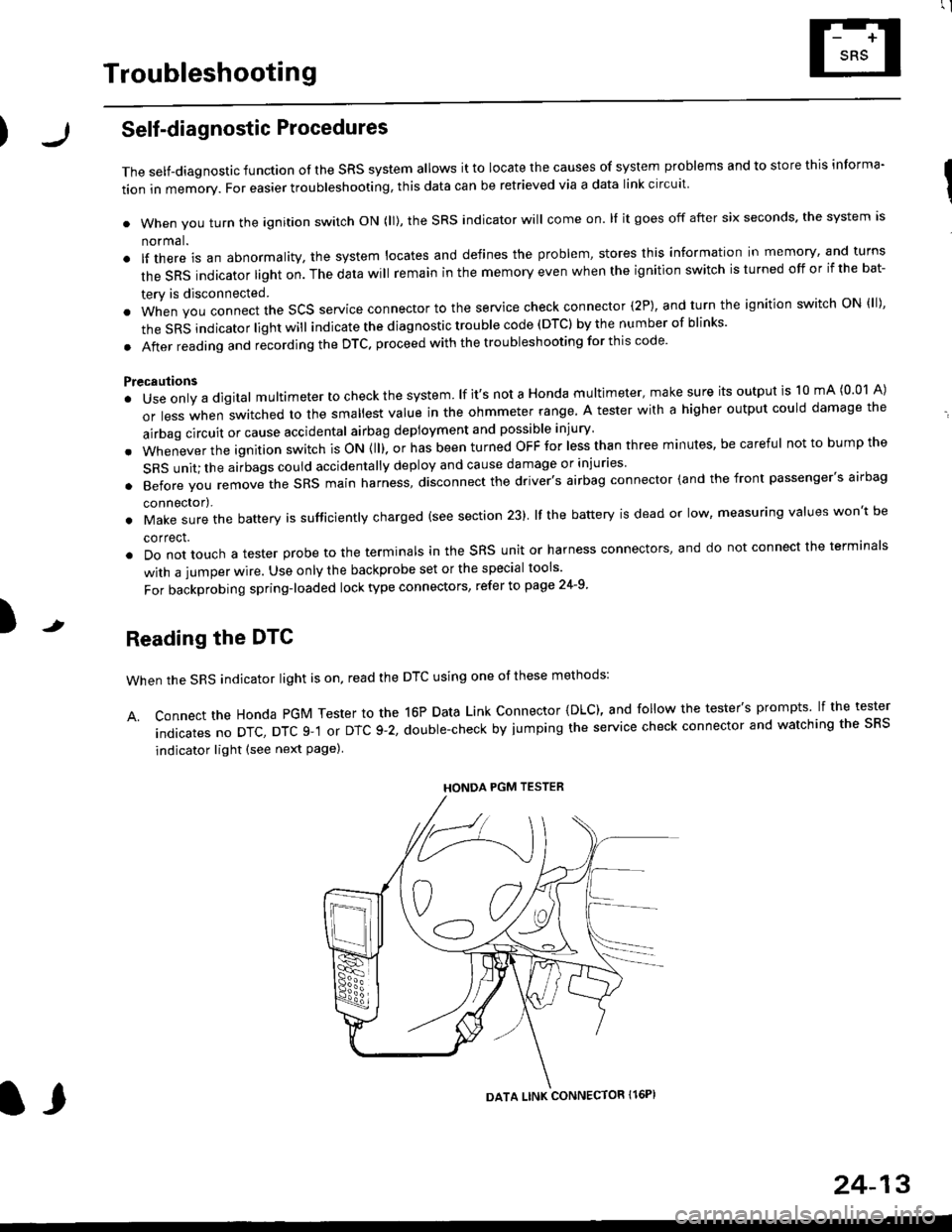
Reading the DTC
when the SRS indicator light is on, read the DTC using one of these methods:
A. Connect the Honda PGM Tester to the 16P Data Link Connector {DLC), and follow the tester's prompts lf the tester
indicatesnoDTc,DTcg-1orDTc9-2,doub|e-checkbyjumpingtheservicecheckconnectorandwatchingthesRS
indicator light (see next Page)
HONDA PGM TESTER
DATA LINK CONNECTOR Il6PI
l,
24-13
Page 1752 of 2189
Troubleshooting
J
J
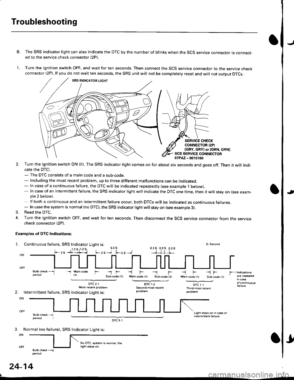
B. The SRS indicator light can also indicate the DTC by the number of blinks when the SCS service connector is connect-ed to the service check connector (2P).
1. Turn the ignition switch OFF, and wait for ten seconds. Then connect the SCS service connector to the service checkconnector (2P). lf you do not wait ten seconds, the SRS unit will not be completely reset and will not output DTCS.
SERVICE CHECKCONNECTOR {2PIIGRY, GRYI or IGRN, cRN]SCS SERVICE CONNECTOR07PAZ - (m10100
l.-zs
2. Turn the ignition switch ON (ll). The SRS indicator light comes on for about six seconds and goes off. Then it will indi,cate the DTC:- The DTC consists of a main code and a sub-code.- Including the most recent problem, up to three different malfunctions can be indicated.- In case of a continuous failure, the DTC will be indicated repeatedly (see example 1 below).- In case of an intermittent failure, the SRS indicator light will indicate the DTC one time, then it will stay on (see exam-ple 2 below).
lf both a continuous and an intermittent failure occur, both DTCS will be indicated as continuous failures.- In case the system is normal (no DTC), the SRS indicator light will stay on (see example 3).3. Read the DTC.
4. Turn the ignition switch OFF, and wait for ten seconds. Then disconnect the SCS service connector from the servicecheck connector (2P).
Examples of DTC Indications:
1. Continuous fallure, SRS Indicator Light isl
- Main @de
DTC21Mosr raenr probtsm
Intermittent failure, SRS lndicator Light is:
-lF- rM.in code ir) Sub.code (2)
DTCI2
-'l F --l FMarn code (11 Sub code t1t
DTCl1Thnd.most recenl
Lrghr srays on rn ca* ol
r --
2.
3. No
ON
sutb chek __.1penod
24-14
rmal (no failure), SRS
DTC5l
Indicator Light is:
rl
No OTC, system is norhal, rhe