1998 HONDA CIVIC engine stop
[x] Cancel search: engine stopPage 517 of 2189
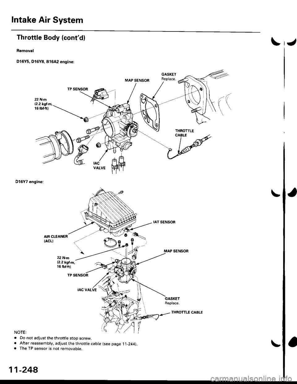
Intake Air System
J
Throttle Body (cont'dl
Removal
D16Y5, Dl6Y8, 81642 engine:
D15Y7 engine:
AIR CLEANER
{ACLI
22 N.m12.2 kgl.m,16 rbf.ftl
NOTE:
. Do not adjust the throttle stop screw.. After reassembly, adjust the throttle cable {see page l l-244).. The TP sensor is not removable.
IAT SENSOR
MAP SENSOR
GASKETReplace.
11-248
THROTTLE CABLE
Page 521 of 2189
Emission Gontrol System
System Description
The emission control system includes a Three Way Cata-lytic Convener (TWC), Exhaust Gas Recirculation (EGR)
system,. Positive Crankcase Ventilation (pCV) system andEvaporative Emission (EVAP) Control system. The emis-sion control system is designed to meet federal and stateemission standards.*: D16Y5 engine
Tailpipe Emission
Inspestion
@@ Do not smoke during ihis procedure. Keepany open flame away from your work area.
1. Start the engine. Hold the engine at 3,000 rpm withno load (in Park or neutral) until the radiator fancomes on. then let it idle.
2. Connect a tachometer.
Check and, if necessary, adjust the idle speed (see
page 11-220 - 223).
Warm up and calibrate the CO meter according to themeter manufacturer's instructions.
Check idle CO with the headlights, heater blower,rear window defogger, cooling fan, and air condition-er off.
NOTE: (Canada) Pull the parking brake lever up.Start the engine, then check that the headlights areoff.
CO mete. should indicate 0.1% maximum.
NOTE: '98 Dl6Y5 engine - lf the idle speed incress-es to 8101 50 rpm, this means the EVAp system ispurging the canister. To stop the purging temporari-ly. raise the engine speed above 1,000 rpm with theaccelerator pedal, then slowly release the pedal.
11-252
eFORWARD -
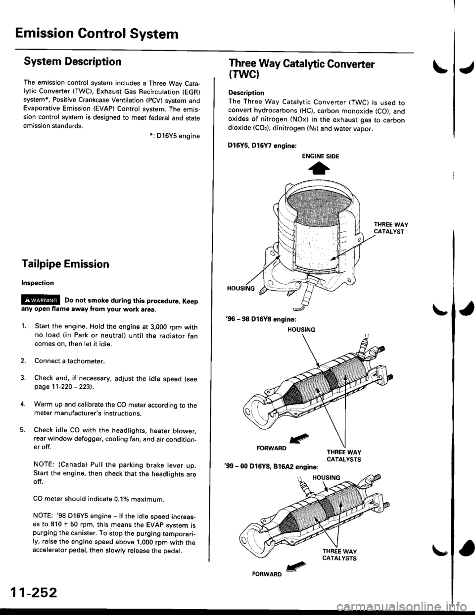
Three Way Catalytic Converter
(TWCI
Doscription
The Three Way Catalytic Converter (TWC) is used toconven hydrocarbons (HC), carbon monoxide (CO), andoxides of nitrogen (NOx) in the exhaust gas to carbondioxide (COr), dinitrogen (N,) and water vapor.
D15Y5, D16
, engine:
'99 - 00 D16Y8, 81642 engine:
ENGINE SIDE
t
Page 584 of 2189
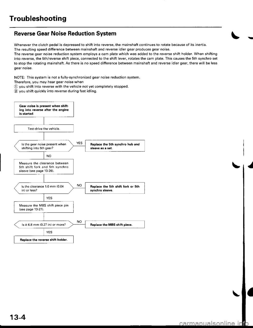
Troubleshooting
Reverse Gear Noise Reduction System
Whenever the clutch pedal is depressed to shift into reverse, the mainshaft continues to rotate because of its inertia.
The resulting speed difference between mainshaft and reverse idler gear produces gear noise.
The reverse gear noise reduction system employs a cam plate which was added to the reverse shift holder. When shifting
into reverse, the sth/reverse shjft piece, connected to the shift lever, rotates the cam plate. This causes the sth synchro set
to stop the rotating mainshaft. As there is no speed difference between mainshaft and reverse idler gear, there will be less
gear norse.
NOTE: This system is not a fully-synchronized gear noise reduction system.
Therefore, you may hear gear noise when
O you shift into reverse with the vehicle not yet completely stopped.
@ you shift quickly into reverse during fast idling.
-
Gear noise is oresent when shift-ing into reverce after the engineis started.
Test-drive the vehicle.
ls the gear noise present whenshifting into 5th gear?Beplace the 5th synchro hub and3leeve e3 a set,
Measure the clearance between5th shift fork and 5th synchrosleeve {see page 13'26).
ls the clearance 1.0 mm (0.04
in) or less?
Measure the MBS shift piece pin(see page 13-27).
ls ( 6.8 mm (0.27 in) or more?Replace the MBS shift piece.
ReDlace the reve6e ahift hold.r.
13-4
Page 682 of 2189
Description
(cont'dl
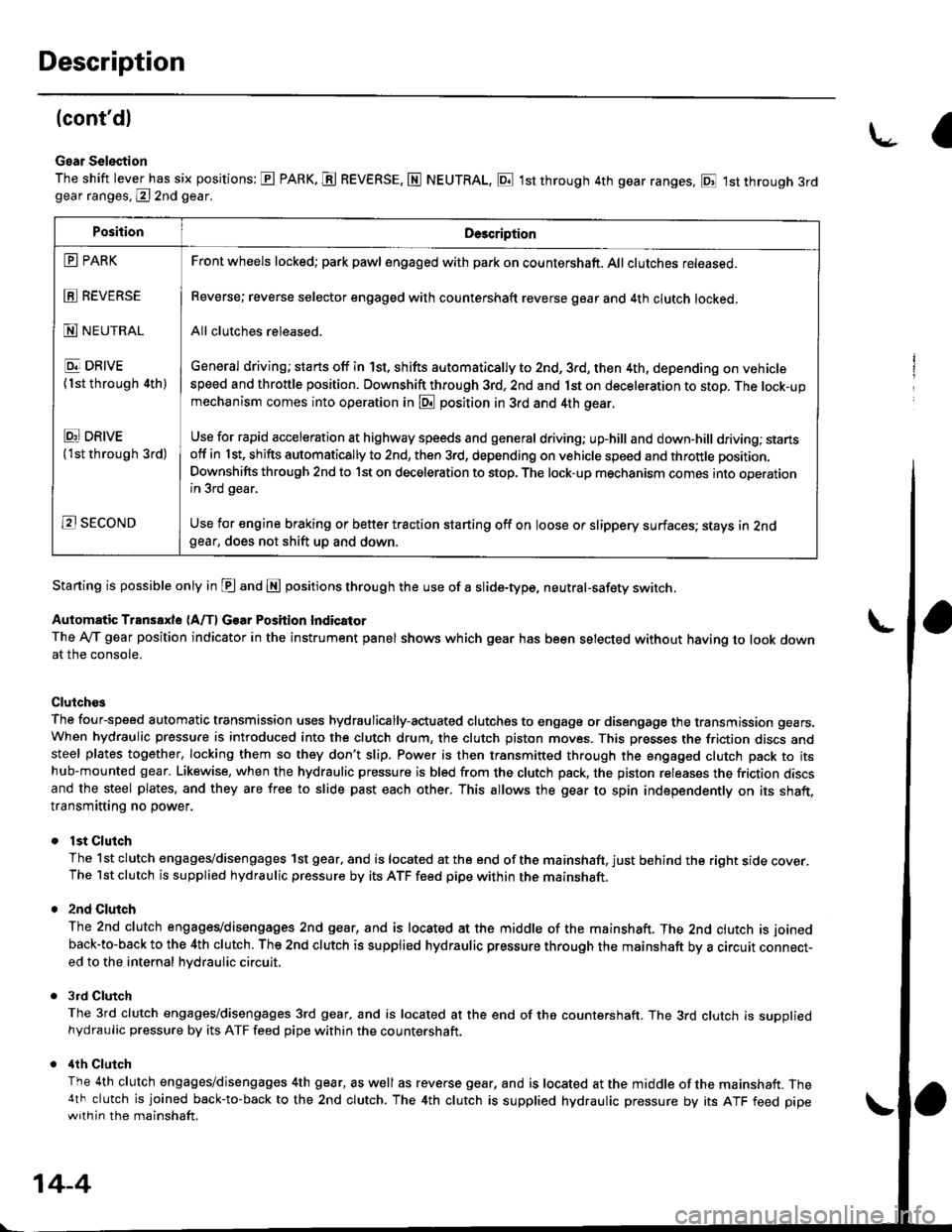
Gear Selection
The shift lever has six positions: E PARK. E REVERSE, N NEUTRAL, E 1st through 4th gear ranges, E 1st through 3rdgear ranges, @ 2nd gear.
Starting is possible only in E and E positions through the use of a slide-type, neutral-safety switch.
Automatic Transaxle (A/f, Gear Position Indicator
The Ay'T gear position indicator in the instrument panel shows which gear has been selected without having to look downat the console.
Clutch€s
The four-speed automatic transmission uses hydraulically-actuated clutches to engage or disengage the transmission gears.When hydraulic pressure is introduced into the clutch drum, the clutch piston moves. This presses the friction discs andsteel plates together, locking them so they don't slip. Power is then transmitted through the engaged clutch pack to itshub-mounted gear. Likewise, when the hydraulic pressure is bled from the clutch pack, the piston releases the friction discsand the steel plates, and they are free to slide past each other. This allows the gear to spin independently on its shaft,transmitting no power.
lst Clutch
The 1st clutch engages/disengages 1st gear, and is located at the end of the mainshaft, just behind the right sroe cover.The 1st clutch is supplied hydraulic pressure by its ATF feed pipe within the mainshaft.
2nd Clulch
The 2nd clutch engagegdisengages 2nd gear, and is located at the middle of the mainshaft. The 2nd clutch is joined
back-to-back to the 4th clutch. The 2nd clutch is supplied hydraulic pressure through the mainshaft by a circutr connect-ed to the internal hvdraulic circuit,
3rd Clutch
The 3rd clutch engages/disengages 3rd gear, and is located at the end of the countershaft. The 3rd clutch is suooliedhydraulic pressure by its ATF feed pipe within the countershaft.
ilth Clutch
The 4th clutch engages/disengages 4th gear, as well as reverse gear, and is located at the middle of the mainshaft. The4th clutch is joined back-to-back to the 2nd clutch. The 4th clutch is supplied hydraulic pressure by its ATF feed pipewith in the mainshaft.
\-a
PositionDe3cription
E PARK
E REVERSE
N NEUTRAL
E DRIVE
{1st through 4th)
Ei DRtvE('lst through 3rd)
B SECOND
Front wheels locked; park pawl engaged with pa* on countershaft. All clutches released.
Reverse; reverse selector engaged with countershaft reverse gear and 4th clutch locked.
All clutches released.
General driving; starts off in 1st, shifts automatically to 2nd, 3rd, then 4th, depending on vehiclespeed and throttle position. Downshift through 3rd, 2nd and 1st on deceleration to stop. The lock-upmechanism comes into operation in @ position in 3rd and 4th gear.
Use for rapid acceleration at highway speeds and general driving; up-hill and down,hill dfiving; stansotf in 1st, shifts automatically to 2nd, then 3rd, depending on vehicle speed and throttle position.
Downshifts through 2nd to lst on deceleration to stop. The lock-up mechanism comes into operationin 3rd gear,
Use for engine braking or better traction starting off on loose or slippery surfaces; stays in 2ndgear, does not shift up and down.
14-4
Page 721 of 2189
I
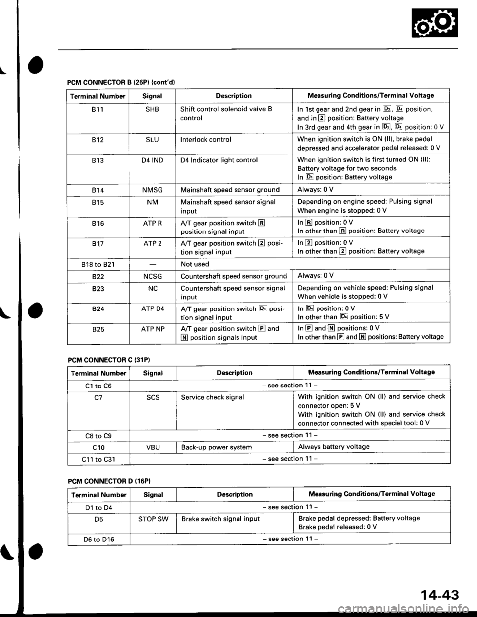
PCM CONNECTOR B {25P1 {cont'dl
Terminal NumberSignalDescriptionMeasuring Conditions/Terminal Vohage
811SHBShift control solenoid valve B
control
In 1st gear and 2nd gear in -q1, q11 position,
and in E] position: Battery voltage
In 3rd gear and 4th gear in lD.J, [Dr- position: 0 V
B't2SLUInterlock controlWhen ignition switch is ON (ll), brake pedal
deoressed and accelerator Dedal released: 0 V
813D4 INDD4 Indicator light controlWhen ignition switch is first turned ON (ll):
Battery voltage for two seconds
In E position: Baftery voltage
B't 4NMSGMainshaft speed sensor groundAlways: 0 V
E tcNMMainshaft speed sensor signal
input
Depending on engine speed: Pulsing signal
When engine is stopped: 0 V
816ATP RAy'T gear position switch Eposition signal input
InE position: 0V
In other than E position: Battery voltage
817ATP 2A/T gear position switch E posi-
tion signal input
InE position: 0V
In orher than E position: Battery voltage
818 to 821Not used
s22NCSGCountershatt speed sensor groundAlwaysr 0 V
B�23NCCountershaft speed sensor signal
input
Depending on vehicle speed: Pulsing signal
When vehicle is stopped: 0 V
B�24ATP D4Ay'T gear position switch lor posi-
tion signal input
InEposition:0V
In other than 6 position: 5 V
ATP NPA,/T gear position switch E and
N position signals input
InE and E positions: 0V
In otherthan E and N] positions: Battery voltage
PCM CONNECTOR C {31P)
Terminal NumberSignalDescriptionMeasuring Conditions/Terminal Voltage
Cl to C6- see section 11 -
c1Service check signalWith ignition switch ON (ll) and service check
connector oDen; 5 V
With ignition switch ON (ll) and service check
connector connected with sDecial tool: 0 V
C8 to Cg- see section 11 -
c10VBUBack-up power systemAlways battery voltage
C11 to C31- see section '11 -
PCM CONNECTOR D (16P}
Terminal NumberSignalDescriptionMeasuring Conditions/Terminal Voltage
Dl to D4- see section 11 -
D5STOP SWBrake switch signal inputBrake pedal depressed: Battery voltage
Brake pedal released: 0 V
D6 to D16- see section 1 l -
14-43
Page 725 of 2189

FCM CONNECTOR D {16P)
\o
14-47
Terminal NumberSignalDo3criptionMeasuring Conditions/Torminal Vohage
D1LCALock-up control solenoid valve A
control
When lock-up is ON: Battery voltage
With no lock-up: 0 V
SHBShift control solenoid valve B
control
In E position, in 1st and 2nd gear in E, E
position: Battery voltage
ln 3rd gear in E, E, in 4th gear in E posi-
tion;0 V
D3LCBLock-up control solenoid valve B
control
When full lock-up: Battery voltage
With half lock-up: Pulsing signal
D4Not used
D5VB SOLLock-up control solenoids, shift
control solenoids and linear
solenoid power supply electrode
with ignition switch oN (ll): Battery voltage
With ignition switch OFF: 0 V
D6ATP RAy'T gear position switch
E position input
tnEposition:0V
In other than E position: Approx. 10 V
SHAShift control solenoid valve A
control
In E] position, in 2nd and 3rd gear in p!, [Q]
position: Battery voltage
In 1st gear in E, @ position, in 4th gear in El
Dosition: 0 V
D8ATP D3A/T gear position switch
E position input
In E position:0V
In otherthan @ position: Approx. 10 V
D9ATP D4Ay'T gear position switch
E position switch
In El position: 0 V
In other than E position: Approx. 5 V
D10NCCountershaft speed sensor signal
input
Depending on vehicle speed: Pulsing signal
When vehicle is stooped: 0 V
D11NMMainshaft speed sensor signal
Inpur
Depending on engine speed: Pulsing signal
When engine is stopped: 0 V
D't2NMSGMainshaft speed sensor ground
D13ATP NPAy'T gear position switch E and
E position input
InE and E positions: 0V
In other than E and E positions: Approx. 10 V
D14AfP 2Ay'T gear position switch
E position input
tnEposition;0V
In other than E position: Approx. 10 V
D16NCSGCountershaft speed sensor
ground
Page 793 of 2189

Accelerate to about 35 mph (57 km/h) so the transmlssion is in 4th, then shift from Dl position to Z position The
vehicle should immediately begin slowing down from engine braking'
CAUTION: Do not shift from -91 or -Dd position to E position at speeds ov6r 63 mph {100 km/hl; You mav damage
the transmission.
Check for abnormal noise and clutch slippage in the following positions'
E (2nd Gear) Position
ll Accelerate from a stop at full throttle. check that there is no abnormal noise or clutch slippage.
b. Upshifts and downshifts should not occur with the selector in this posirion'
E (Reverse) Position
i"ccelerate from a stop at fullthrottle, and check for abnormal noise and clutch slippage'
Test in B (Park) Position
Park the vehicle on slope (approx. l6'), apply the parking brake' and shift into E position Belease the brake; the veh'
cle shou,d nol move
1+115
Page 797 of 2189

Pressure Testing
@I While testing, be caroful of th€ rotating front wheels.
. Make sure lifts, iacks, and satoty stands are placod properly (see section 1)'
CAUTION:
. Beforo iesting, be sure the transmission fluid is tilled to tho proper level'
. Warm up tho engine before testing'
1. Raise the vehicle (see section 1).
2. Warm up the engine, then stop the engine and connect a tachometer'
3. Connect the oil pressure gauges to each inspection hole.
TOROUE: 18 N.m (1.8 kgf'm, 13 lbnft)
cAUTloN: connact the oil pressuro gauges securely; be suro not to allow dust and other foreign Parlicles to entel
the inspestion holos'
A/T OIL PRESSURE GAUGESET w/PANEL07t06 - 0020400
A/T LOW PRESSURE GAUGE
SET WPANEL07406 - 0070300
A/T OIL PRESSURE HOSEADAPTER07Mru - PY0120(4 requiJedl
A/T OIL PBESSURE HOSE
2210 mmOTMAJ - PY4{)llA
14 roquircdl
Start the engine, and measure the respective ptessure as follows'
a Line Pressure
. 1st Clutch Pressure
. 2nd,3rd and 4th Clutch Pressure
Install a new washer and the sealing bolt in the inspection hole. and tighten to the specified torque'
TOROUE: l8 N.m (1.8 kgf'm,13lbf'ft)
NOTE: Do not reuse old sealing washers; always replace washers'
(cont'd)
14-119